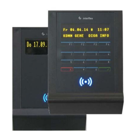
Interflex IF-800/W02 User manual

Interflex Datensysteme GmbH 1/7
1 IF-800/W02 Terminal (Slave)
Thank you for choosing an Interflex system. With this slave terminal, you
have purchased a reliable device for access control.
Scope of delivery:
The following is included in the package:
W02 housing cover
Reader housing with encapsulated RFID electronics and 5 m connecting
cable
I/O controller board with address switch
Mounting plate for fastening
Material for wall mounting
Please check the completeness and condition of the shipment upon
receipt.
2 Function
Slave terminals of series IF-800 W02 are used for:
1. controlling the access of people who identify themselves via an RFID credential before entering a
security zone.
2. controlling and monitoring locking devices that prevent uncontrolled (physical) access to security zones.
3. writing NetworkOnCard access rights. The data is used for identification at offline devices, e.g. PegaSys
terminals.
A higher-ranking device, such as a terminal controller or a master terminal, is required for operation.
95-10327_ V2016-10-20 IF800_W02
IF-800/W02

Interflex Datensysteme GmbH 2/7
3 Hardware Components
The slave terminal consists of the following components:
4 Shielded Cables
To guarantee trouble-free operation, we recommend the use of shielded cables.
Operation, however, is also possible with unshielded cables. Data transfer problems must be examined on a
case-by-case basis. Where necessary, a shielded cable must be used for the corresponding devices.
5 How to Proceed During Installation
The following installation procedure has been proven and tested:
1. Install the electric cables required for operation.
2. Install the power supply.
3. Fasten the reader housing and the I/O controller board.
4. Set the address.
5. Connect the electrical cables.
6. Check the functions.
7. Close the W02 housing cover.

Interflex Datensysteme GmbH 3/7
6 Electrical Connections
The figure below shows the electrical connections for door management and door monitoring. Installations
without door monitoring do not require sensors (13) or opening push-buttons (12) and the cables can be
omitted.
All cables must be laid to the I/O controller board.
The 5 m long reader cable (1) can be extended to 100 m.
For information on the connection, see: (Connections on the I/O Controller Board).
10 Housing for the installation of power packs and the I/O
board 12 Opening push-button or handle contact
11 Electric actuator up to 30 V, 2 A 13 Door sensor for monitoring the locking device
Figure Possible Connections and Electrical Wiring
Cable
No. Max. Length Cable Cores
1 Reader/ COM cable, preferably laid in empty conduit 100 m 4 x 2 x 0.6 mm²
2 Control line for electric actuator No
specifications 2 x 2 x 0.6 mm²
3 Cable to door sensor, handle contact or opening push-button 100 m 2 x 2 x 0.6 mm²
4 RS485 BUS cable to higher-ranking device 1200 m 2 x 2 x 0.6 mm²
4a RS485 spur line from BUS cable to installation site 100 m 2 x 2 x 0.6 mm²
5 Mains cable No
specifications NYM 3 x 1.5 mm²
Only use shielded connecting cables, e.g. cable type J-Y(ST)Y.
The above-specified cable lengths may not be exceeded. Excessive lengths can cause malfunctions.
The power supply must have a separate fuse protection.
The power supply of the access control element must be provided separately.
The recommended distance between cables and power lines is 10 cm.
If the locking device is monitored, a handle contact or door opening switch must be installed. The
switching of the contact allows for the locking device to be opened without setting off an alarm when
exiting the security zone.

Interflex Datensysteme GmbH 4/7
7 Installation
The reader (IP 65) can be installed on a flat wall or pillar, both indoors and outdoors.
The mounting plate (2) is used for fastening. The holes are designed for screw fastening to flat walls and
also to DIN appliance cases.
Snap-in elements (3a) in the housing cover (3) lock into place when the cover is pressed onto the mounting
plate (2) and thus, prevent the loosening of the cover.
The mounting plate must not get twisted out of shape when it is screwed down.
The countersunk screws must end up flush with the countersunk holes and not protrude.
There should be a distance of at least 20 cm from other devices with RFID readers.
When the device is mounted on a metal surface, the reading distance is reduced.
Close housing: The housing cover (3) is first placed over the reader electronics during initial operation. To
close the housing, the cover is positioned over the housing and pressed down until the snap-in elements lock
into place in the mounting plate.
1 Reader housing with reader electronics 3 Housing cover
1a 5 m reader cable for connection to I/O controller board 3a Snap-in elements in cover
2 Mounting plate 4 I/O controller board with address switches
2a Drilling for reader cable
7.1 Installation of the I/O Controller Board
The I/O controller board (4) can be installed in a distance of up to 100 m from the reader housing (1).
The I/O controller board must be installed in a secured area, e.g. in a DIN appliance
case or in a housing together with the power supply.

Interflex Datensysteme GmbH 5/7
8 Setting the Address
An address must be set for identification.
Address setting for the connection to a terminal controller or an access manager:
It is common practice to assign the first slave terminal on each RS485 BUS to address 1, the second to
address 2, and so on.
Address setting for the connection to a master terminal:
It is common practice to assign the first slave terminal to address 2, the second to address 3, and so on.
Before making the settings, check the BUS address section of the higher-ranking device, such as, e.g., a
master terminal. You can do so by using a remote program, e.g. Telnet, and entering the OC command "cfg".
Furthermore, please check if the address of the terminal already exists on this BUS. It is not allowed to
assign identical addresses to one RS485 BUS.
Switch off the power supply prior to changing an address.
Switch: 1 2 3 4
Address 1 (A) OFF OFF OFF OFF (not required if connected to a master terminal)
Address 2 (B) ON OFF OFF OFF
Address 3 (C) OFF ON OFF OFF (as shown in the figure above)
Address 4 (D) ON ON OFF OFF
Address 5 (E) OFF OFF ON OFF
Address 6 (F) ON OFF ON OFF
Address 7 (G) OFF ON ON OFF
Address 8 (H) ON ON ON OFF

Interflex Datensysteme GmbH 6/7
9 Connections on the I/O Controller Board
To maintain the required EMC values, the protective earth conductor and also the cable shields must be
connected as shown in the figure below.
For information on the connection of the RS485 data line to a terminal controller or master terminal, please
refer to the installation and wiring instructions included in the delivery of the respective device.
1 IF-800/W02 6 Example: Door monitoring connection
2 I/O controller board 7 Address switch
3 Power supply example Br1 Bridge is removed if the I/O controller board is to be used
as an expansion
4 Example: Connection of the RS485 data line Br2 Setting the relay output to normally open / normally closed
5 Example: Connection of an actuator Br3 Contact for monitoring the housing

Interflex Datensysteme GmbH 7/7
10 Technical Specifications
Power Supply
Low-voltage 12-24 VAC/DC
Power consumption Max. 4 VA
Protection Self-resetting fuse
Interface to parent devices RS485, 9600/ 19200 baud (automatic configuration)
RFID reader according to order Mifare, LEGIC or Proxif reading technology
Read range Up to 50 mm, depending on the size of the identification
medium used
Inputs for floating sensors 4 floating sensors (2 per each I/O controller board)
Output relays 2 relays with max. 30V 2A (1 per each I/O controller board)
Switching power Up to 30V, 2A
User information Buzzer; blue, red and green LEDs
Device Protection
Protection category III
Degree of protection Reader IP65, encapsulated electronics
I/O board IP 00
General Data
Ambient temperature -25°C to +55°C
Humidity Max. 95%, non-condensing
Product safety EN 60950-1
Compatibility (EMC) EN 300330-1/-2 EN 301489-1/-3
Dimensions (H x W x D) 119 x 77 x 23 mm (reader), 52 x 30 x 16 mm (I/O board)
Weight Approx. 0.4 kg
Installation type Surface-mounted
Color Anthracite or light gray
11 Disposal
Once its service life comes to an end, the device must be disposed of properly as
electronic waste. The owner can dispose of the device himself or return it to the
supplier.
Copyright © 2016 Version Date: October 31, 2016
Interflex Datensysteme GmbH
Zettachring 16, D-70567 Stuttgart, Germany Tel.: +49 (0711) 1322 0
Internet E-Mail: interflex.info@allegion.com Websites: www.interflex.de www.allegion.com
Table of contents
Other Interflex RFID System manuals
Popular RFID System manuals by other brands
Siemens
Siemens SIMATIC Ident CB Gate operating instructions
MegaPoints Controllers
MegaPoints Controllers System2 Starter Kit User reference

Intelleflex
Intelleflex CMR-6100 user manual
Elatec
Elatec MULTITECH 2 LEGIC M user manual

SILLA
SILLA PRISM SOLAR RFID Instructions for installation, use and maintenance manual
Balluff
Balluff BF-IDM07 operating guide
