manuals.online logo
Brands
  1. Home
  2. •
  3. Brands
  4. •
  5. Intermatic
  6. •
  7. Timer
  8. •
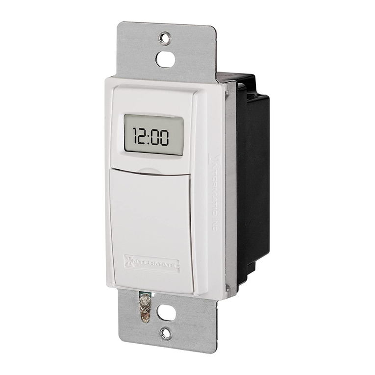
  9. Intermatic EI220W-1 User manual

Intermatic EI220W-1 User manual

EI220W-1
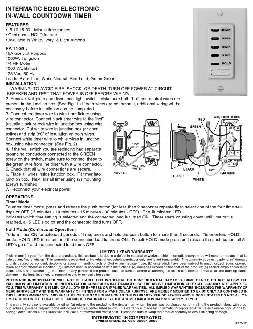
NEUTRAL (WHITE)
HOT
(Black or
Red)
FIGURE 2
WIRE FROM FIXTURE
HOT
1. Disconnect power to the circuit.
2. Remove wall plate and disconnect light switch.
3. Make sure both “hot” and neutral wires are present in the junction
box. (See Fig. 1.)
NOTE: If both wires are not present, additional wiring will be
necessary before installation can be completed. Remove insulation
from each conductor and make sure ends of wire are straight.
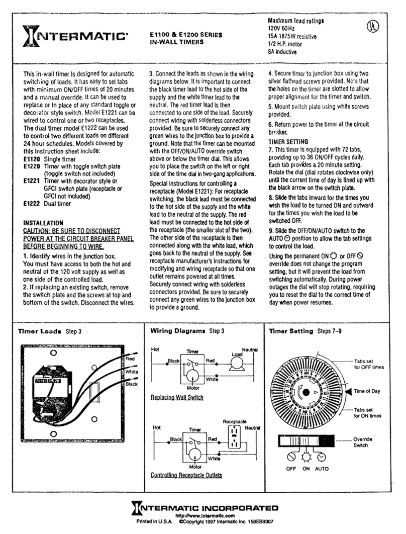
4. Connect red timer wire to load wire and secure with a wire
connector. (See Fig. 2)
5. Connect black timer wire to the “hot” wire in junction box and
secure with a wire connector.
6. Cut white wire in junction box (or open splice) and strip 7/16” of
insulation on both wires.
7. Connect white timer wire to white wires in junction box and secure
with wire connector. (See Fig. 2)
8. Connect the green wire from timer to the existing ground in box.
9. Verify all wire connections are secure.
10. Place timer and all wires inside junction box.
11. Install the timer and secure with supplied mounting screws.
12. Reconnect power to circuit.
• Disconnect power at the circuit breaker(s) or disconnect switch(es) before installing or servicing.
• Installation and/or wiring must be in accordance with national and local electrical code requirements.
• Connect to copper conductors only.
• Do NOT use timer to control devices that could have dangerous consequences due to inaccurate timing
such as sun lamps, sauna, heaters and slow cookers.
• No user-serviceable parts.
Risk of Fire or Electric Shock
WARNING
NOTICENOTICE
IMPORTANT SAFETY INSTRUCTIONS
SAVE THESE INSTRUCTIONS
MODEL EI220W-1
• 15 A General Purpose
• 15 A Resistive
• 1000 W Tungsten
• 1 HP Motor
• 500 VA Electronic Ballast
• 1000 VA Ballast
• 120 VAC, 60Hz Input Voltage
• Leads: Black-Line, White-Neutral, Red-Load, Green-Ground
Ratings:
Operation:
Installation:
LIMITED WARRANTY
Warranty service is available by either (a) returning the product to the dealer from whom the unit was
purchased or (b) completing a warranty claim online at www.intermatic.com. This warranty is made by:
Intermatic Incorporated, 1950 Innovation Way, Suite 300, Libertyville, IL 60048. For additional product or
warranty information go to: http://www.Intermatic.com or call 815-675-7000.
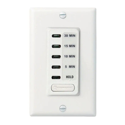
Timer Mode
Press and release timer button repeatedly to select the desired time setting or to select OFF. The
illuminated LED indicates which time setting is selected and the connected load is turned ON. After the
selected time interval counts down, the LED and the connected load turns OFF.
Hold Mode (Continuous Operation)
To turn timer ON for extended periods of time, press and hold the timer button for more than 2 seconds.
Timer enters HOLD mode, HOLD LED turns on, and the connected load is turned ON. To exit HOLD mode
press and release the timer button. LED goes off and the connected load turns OFF.
FIGURE 1
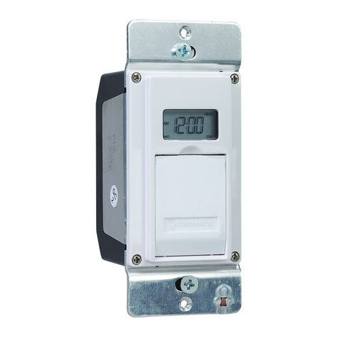
In-Wall CountdownTimer with Hold Feature
1. Couper l’alimentation électrique du circuit.
2. Déposer la plaque murale et débrancher l’interrupteur d’éclairage.
3. Vérifier qu’il y a à la fois un fil de phase et un fil de neutre dans la boîte de dérivation (voir Fig. 1).
REMARQUE: S’il n’y a pas ces deux fils, il peut être nécessaire de tirer des câbles
supplémentaires avant de pouvoir effectuer l’installation. Dénuder chaque conducteur et
s’assurer que l’extrémité des fils est bien droite.
4. Raccorder le fil rouge de la minuterie au fil du charge à l’aide d’une marrette (voir Fig. 2).
5. Raccorder le fil noir de la minuterie au fil de phase dans la boîte de dérivation à l’aide d’une
marrette.
6. Couper le fil blanc dans la boîte de dérivation (ou ouvrir l’épissure) et dénuder 11mm d’isolant
environ sur les deux fils.
7. Raccorder le fil blanc de la minuterie aux fils blancs dans la boîte de dérivation à l’aide d’une
marrette (voir Fig. 2).
8. Raccorder le fil vert de la minuterie à la terre existante dans la boîte.
9. Vérifier que tous les fils sont solidement raccordés.
10. Placer la minuterie et tous les fils à l’intérieur de la boîte de dérivation.
11. Attacher la minuterie avec les vis de fixation fournies.
12. Rebranchez l’alimentation au circuit.
• Débrancher l’alimentation au niveau des disjoncteurs ou des sectionneurs avant de procéder à l’installation ou
à l’entretien.
• L’installation et/ou le câblage doivent être conformes aux exigences du code de l’électricité en vigueur.
• Raccorder exclusivement à des conducteurs en cuivre.
• Ne PAS utiliser la minuterie pour manipuler les dispositifs qui pourraient avoir des conséquences dangereuses
en raison de chronométrages imprécis tels que lampes solaires, saunas, chauffes-eau et mijoteuses.
• Aucune pièce réparable par l’utilisateur.
AVISAVIS
INSTRUCTIONS DE SÉCURITÉ IMPORTANTES
CONSERVER CES INSTRUCTIONS
MODÈLE EI220W-1
• 15 A usage général
• 15 A Résistif
• 1000 W tungstène
• 1HP moteur
• 500 VA ballast électronique
• 1000 VA ballast
• 120 V c.a., 60Hz Tension d’entrée
• Fils: Noir-phase, blanc-neutre, rouge-charge, vert-terre
Caractéristiques :
Fonctionnement :
Pose :
Mode minuterie
Appuyez sur et relâchez le bouton de la minuterie pour sélectionner le réglage de l’heure désirée ou
pour sélectionner OFF. Le voyant lumineux indique quel réglage de durée est sélectionné et la charge
raccordée à la minuterie est mise tension. À la fin du compte à rebours de l’intervalle de temps
sélectionné, le voyant s’éteint et la charge raccordée est désactivée.
Mode Hold (fonctionnement continu)
Pour mettre la minuterie en mode de marche pendant des durées prolongées, tenir la touche de la
minuterie enfoncée pendant plus de 2 secondes. La minuterie passe alors en mode HOLD (maintien), le
voyant HOLD s’allume et la charge raccordée est mise sous tension. Pour quitter le mode HOLD, appuyer
brièvement sur la touche de la minuterie. Le voyant s’éteint et la charge raccordée est désactivée.
Minuterie murale à compte à rebours avec fonction «suspendre»
NEUTRE
(BLANC)
PHASE
(noir ou
rouge)
FIGURE 2
FIL DU LUMINAIRE
ROUGE
VERT
NOIR
BLANC
TERRE
FIGURE 1
PHASE
AVERTISSEMENT
Risque d’incendie
de choc électrique
EI220W-1
158--02246REF
NEUTRO
(BLANCO)
CON
ELECTRICIDAD
(Negro o rojo)
FIGURA 2
CABLE DESDE LA
LUMINARIA
ROJO
VERDE
NEGRO
BLANCO
TIERRA
1. Desconecte la energía hacia el circuito.
2. Retire la placa de la pared y desconecte el interruptor de luz.
3. Asegúrese de que los cabes “con electricidad” y neutros se encuentren en
la caja de empalmes. (Consulte la Fig. 1).
NOTA: Si no se encuentra ninguno de ellos, será necesario colocar cableado
adicional antes de completar la instalación. Retire el aislamiento de cada
conductor y asegúrese de que los extremos del cable estén rectos.
4. Conecte el cable rojo del temporizador al cable de la carga y fíjelo con
un conector de cables. (Consulte la Fig. 2).
5. Conecte el cable negro del temporizador al cable con electricidad en la
caja de empalmes y fíjelo con un conector de cables.
6. Corte el cable blanco en la caja de empalmes (o abra el empalme) y quite
1,1 cm de aislamiento en ambos cables.
7. Conecte el cable blanco del temporizador a los cables blancos de la caja
de empalmes y fíjelos con el conector de cables. (Consulte la Fig. 2).
8. Conecte el cable verde del temporizador a la conexión a tierra existente
en la caja.
9. Verifique que todos las conexiones de cables estén firmes.
10. Coloque el temporizador y todos los cables al interior de la caja de
empalmes.
11. Instale el temporizador y fíjelo con los tornillos de montaje que se
proporcionan.
12. Vuelva a conectar la potencia al circuito.
• No contiene piezas a las que le pueda realizar mantenimiento.
AVISOAVISO
INSTRUCCIONES IMPORTANTES DE SEGURIDAD
GUARDE ESTAS INSTRUCCIONES
MODELO EI220W-1
• 15 A propósito general
• 15 A resistivo
• 1000 W tungsteno
• Motor de 1 HP
• 500 VA balasto electrónico
• 1000 VA balasto
• 120 V CA, 60 Hz Voltaje de entrada
• Conductores: Negro: Línea; Blanco: Neutro; Rojo: Carga; Verde:Tierra
Clasificaciones:
Funcionamiento:
Instalación:
Modo de temporizador
Presione y suelte el botón del temporizador varias veces para seleccionar el ajuste de tiempo deseado o para seleccionar
OFF. La luz LED encendida indica qué ajuste de tiempo está seleccionado y se ENCIENDE la carga conectada. Después de
que se acaba el intervalo de tiempo seleccionado, la luz LED y la carga conectada se APAGAN.
Modo de mantenimiento (funcionamiento continuo)
Para ENCENDER el temporizador por períodos de tiempo prolongados, mantenga presionado el botón del temporizador
por más de 2 segundos. El temporizador entra en el modo HOLD (Mantenimiento), se enciende la luz LED HOLD y se
ENCIENDE la carga conectada. Para salir del modo HOLD, presione y suelte el botón del temporizador. La luz LED y la
carga conectada se APAGAN.
FIGURA 1
Temporizador de pared de cuenta regresiva con función de “retención”
ADVERTENCIA Riesgo de incendio
CON
ELECTRICIDAD
GARANTÍA LIMITADA
Este servicio de garantía está disponible mediante (a) la devolución del producto al proveedor al que se
le compró la unidad; o (b) el llenado de una reclamación de garantía en línea en www.intermatic.com.
Esta garantía la otorga: Intermatic Incorporated, 1950 Innovation Way, Suite 300, Libertyville, IL 60048. Para
obtener servicios de garantía, ingrese a: http://www.Intermatic.com o llame al 815-675-7000.
GARANTIE LIMITÉE
Ce service de garantie est disponible (a) en retournant le produit au vendeur auprès duquel l’unité a été achetée ou (b) en remplissant un formulaire en ligne de réclamation de garantie sur www.intermatic.com.
Cette garantie est faite par : Intermatic Incorporated, 1950 Innovation Way, Suite 300, Libertyville, IL 60048. Pour les services de garantie, accédez à la page suivante : http://www.Intermatic.com ou appelez au
815-675-7000
• Desconecte la energía desde los disyuntores o desde los interruptores antes de realizar la instalación o el
mantenimiento.
• La instalación y el cableado se deben realizar de acuerdo con los requisitos del Código Eléctrico Nacional y Local.
• Conecte solo conductores de cobre.
• NO se debe usar el temporizador para controlar dispositivos que pudieran tener consecuencias peligrosas debido
a la regulación imprecisa del tiempo, como por ejemplo, lámparas solares, saunas, calefactores y ollas de cocción
lenta.
o descarga eléctrica
EI220W-1

Other Intermatic Timer manuals

Intermatic DT27 User manual

Intermatic

Intermatic DT27 User manual

Intermatic HB51RC75 User manual

Intermatic

Intermatic HB51RC75 User manual

Intermatic KM2ST-1G User manual

Intermatic

Intermatic KM2ST-1G User manual

Intermatic EC200WK User manual

Intermatic

Intermatic EC200WK User manual

Intermatic HB1116K User manual

Intermatic

Intermatic HB1116K User manual

Intermatic HB35R Manual

Intermatic

Intermatic HB35R Manual

Intermatic DT300 Series User manual

Intermatic

Intermatic DT300 Series User manual

Intermatic ET2745 Manual

Intermatic

Intermatic ET2745 Manual

Intermatic ET724 User manual

Intermatic

Intermatic ET724 User manual

Intermatic EI400 Series Guide

Intermatic

Intermatic EI400 Series Guide

Intermatic E1022 Guide

Intermatic

Intermatic E1022 Guide

Intermatic C8865 Manual

Intermatic

Intermatic C8865 Manual

Intermatic CT2000 Series User manual

Intermatic

Intermatic CT2000 Series User manual

Intermatic ST01K SERIES Guide

Intermatic

Intermatic ST01K SERIES Guide

Intermatic DT620CL Series Guide

Intermatic

Intermatic DT620CL Series Guide

Intermatic HB350 Series User manual

Intermatic

Intermatic HB350 Series User manual

Intermatic WH2725AT Manual

Intermatic

Intermatic WH2725AT Manual

Intermatic EI600 Series Guide

Intermatic

Intermatic EI600 Series Guide

Intermatic PB300E Series Manual

Intermatic

Intermatic PB300E Series Manual

Intermatic TN311K Guide

Intermatic

Intermatic TN311K Guide

Intermatic T101 User manual
Intermatic

Intermatic T101 User manual

Intermatic AL300 User manual

Intermatic

Intermatic AL300 User manual

Intermatic TN111 Manual

Intermatic

Intermatic TN111 Manual

Intermatic EJ351 Guide

Intermatic

Intermatic EJ351 Guide

Popular Timer manuals by other brands

Dewenwils HOMT11B instruction manual

Dewenwils

Dewenwils HOMT11B instruction manual

ALZA BWV-YC-EU-GY user manual

ALZA

ALZA BWV-YC-EU-GY user manual

ASA Electronics Flight Timer instruction manual

ASA Electronics

ASA Electronics Flight Timer instruction manual

REX MicroRex D22 quick start guide

REX

REX MicroRex D22 quick start guide

Grasslin thermio eco b1 operating manual

Grasslin

Grasslin thermio eco b1 operating manual

Handife BX-6811 instruction manual

Handife

Handife BX-6811 instruction manual

Daktronics P1753 DISPLAY MANUAL

Daktronics

Daktronics P1753 DISPLAY MANUAL

Toro LawnMaster 53603 owner's manual

Toro

Toro LawnMaster 53603 owner's manual

RTC AP21 Series Operation & service manual

RTC

RTC AP21 Series Operation & service manual

Unipro 3004A quick guide

Unipro

Unipro 3004A quick guide

Gardena C14 operating instructions

Gardena

Gardena C14 operating instructions

COMECO CT03 Operation manual

COMECO

COMECO CT03 Operation manual

Emos ESI2001 manual

Emos

Emos ESI2001 manual

elero AstroTec-915ac operating instructions

elero

elero AstroTec-915ac operating instructions

CDC Elettromeccanica TX40 manual

CDC Elettromeccanica

CDC Elettromeccanica TX40 manual

Somogyi Home 0760S instruction manual

Somogyi

Somogyi Home 0760S instruction manual

Grasslin talento 881 pro operating manual

Grasslin

Grasslin talento 881 pro operating manual

Prince Castle 755-HM8 Specifications

Prince Castle

Prince Castle 755-HM8 Specifications

manuals.online logo
manuals.online logoBrands
  • About & Mission
  • Contact us
  • Privacy Policy
  • Terms and Conditions

Copyright 2025 Manuals.Online. All Rights Reserved.