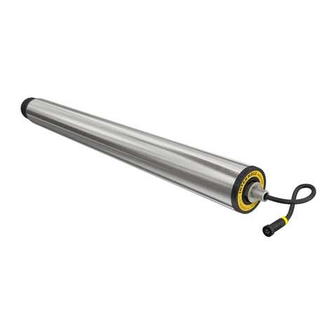
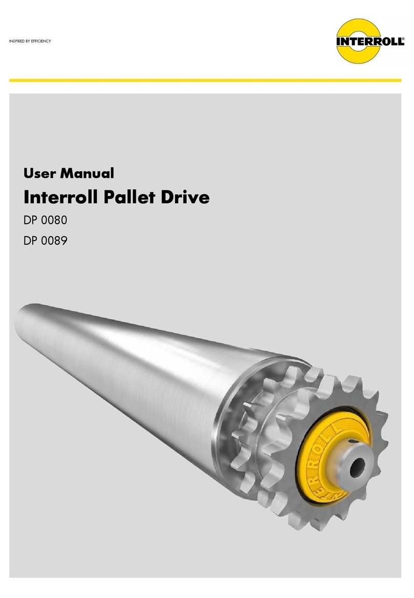
Interroll RollerDrive EC310 User manual

INSPIRED BY EFFICIENCY
Operating manual
Interroll RollerDrive EC310
Interroll RollerDrive EC310 DF
Interroll RollerDrive EC310 IP66

Manufacturer details
Interroll Engineering GmbH
Höferhof 16
42929 Wermelskirchen, Germany
Tel.: +49 (0) 2193 23 0
Fax: +49 (0) 2193 2022
www.interroll.com
Content
We have carefully compiled the content of this document and made every eort to ensure that the information
is correct, complete and up to date. However, we cannot assume any kind of guarantee for this information. We
expressly exclude any liability for any damage or consequential damage connected with the use of this document. We
reserve the right to modify the documented products and product information at any time.
Copyright/industrial property rights
Text, images, graphics and similar elements as well as their arrangement are subject to copyright protection and other
protective laws. The reproduction, alteration, transfer or publication of this document in full or in part is prohibited
in every form. This document is solely for informational purposes and the intended use and does not entitle to the
reproduction of the products in question. All the marks contained in this document (protected trademarks, such as
logos and commercial designations) are the property of Interroll Engineering GmbH or third parties and may not be
used, copied or distributed without prior written consent.

Version 3.1 (02/2019)
Translation of the original operating manual
3 of 42
Contents
1 About this document 7
1.1 Information about this operating manual 7
1.2 Warning notices in this document 8
1.3 Symbols 9
2 Safety-related information 10
2.1 State of the art 10
2.2 Proper use 10
2.3 Improper use 11
2.5 Dangers 12
Injury to persons 12
Electricity 12
Rotating parts 12
Heat 12
Work environment 12
Faults in operation 12
Maintenance 13
Unintentional start-up 13
2.6 Interface to other devices 13
2.7 Operating modes/operating phases 13
Standard operation 13
Special operation 13
3 Product information 14
3.1 Components 14
3.2 Product description 15
Overload protection 15
3.3 Rating plate 16
3.6 RollerDrive performance data 19
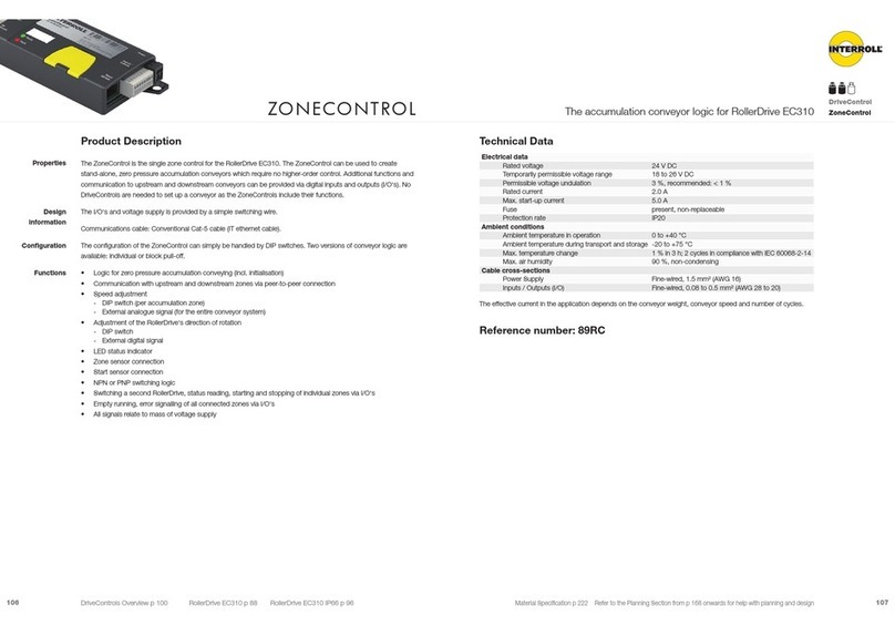
3.7 Controls for the RollerDrive EC310 19
3.8 RollerDrive connector 20
3.9 Dimensions of the motor shaft 21

4 of 42
Version 3.1 (02/2019)
Translation of the original operating manual
Contents
3.10 Dimensions of the bearing housings on the non-cable side 21
EC310 and EC310 DF 21
EC310 IP66 23
4 Transport and storage 24
4.1 Transport 24
4.2 Storage 24
5 Assembly and installation 25
5.1 Warning notices for installation 25
5.2 Installing the RollerDrive 26
Installing the attachment shaft 26
Attaching the non-cable side 27
The Interroll Interlock (optional) 29
5.3 Installation tool (accessory) 30
5.4 Warning notices for electrical installation 31
5.5 Electrical installation 32
6 Start-up and operation 33
6.1 Warning notices for start-up and operation 33
6.2 Start-up 33
Check before the initial start-up 33
6.3 Operation 34
Check before every start-up 34
6.4 Procedure in the event of accidents or faults 34
7 Maintenance and cleaning 35
7.1 Maintenance 35
Checking the RollerDrive 35
Replacing the RollerDrive 35
7.2 Cleaning 36
8 Assistance in the event of faults 37
8.1 Troubleshooting 37

Version 3.1 (02/2019)
Translation of the original operating manual
5 of 42
Contents
9 Decommissioning and disposal 38
9.1 Decommissioning 38
9.2 Disposal 38
10 Appendix 39
10.1 Accessories 39
Interroll controls 39
Interroll power supply unit 39
RollerDrive extension cable 39
PolyVee belt 40
PolyVee clamping aid 40
Tool 40
10.2 Translation of the original Declaration of Conformity 41


Version 3.1 (02/2019)
Translation of the original operating manual
7 of 42
About this document
1 About this document
1.1 Information about this operating manual
This operating manual covers the following Interroll motor rollers:
• RollerDrive EC310
• RollerDrive EC310 DF (DF = Deep Freeze, for refrigeration applications)
• RollerDrive EC310 IP66 (with higher protection rate)
In the course of this manual, the term "RollerDrive" will sometimes be used without specifying the type designation
"EC310".
The operating manual is a component of the product and contains important advice and information regarding the
The currently applicable version of this operating manual can be found online at: www.interroll.com/support/
All the information and advice in this operating manual has been compiled with respect to applicable standards and
regulations as well as the current state of the art.
For special versions, in addition to this operating manual, particular contractual arrangements and technical
documents apply.
¾
¾Keep this operating manual within close reach of the RollerDrive.
¾Pass this operating manual onto every subsequent owner or user.
The manufacturer assumes no liability for damage and malfunctions that occur as a result of non-
compliance with this operating manual.
Should you still have any unanswered questions after reading this operating manual, please contact Interroll
customer service. Contact details for your region can be found online at www.interroll.com/contact/

8 of 42
Version 3.1 (02/2019)
Translation of the original operating manual
About this document
1.2 Warning notices in this document
Warning notices are provided in the context in which danger can occur and describe the nature of the danger in
question. They are structured according to the following examples:
SIGNAL WORD
Type and source of hazard
Consequence(s) in the event of non-compliance
¾Measure(s) for avoiding hazard
Signal words indicate the type and severity of the consequences if measures to avoid the hazard are not observed.
DANGER
Denotes an imminent hazard.
If measures to avoid the hazard are not observed, death or severe injury will occur.
¾Preventive measures
WARNING
Denotes a potentially hazardous situation.
If measures to avoid the hazard are not observed, death or severe injury may occur.
¾Preventive measures
CAUTION
Denotes the possibility of a hazardous situation.
If measures to avoid the hazard are not observed, minor or moderate injury may occur.
¾Preventive measures

Version 3.1 (02/2019)
Translation of the original operating manual
9 of 42
About this document
NOTE
Denotes a situation that can lead to material damage.
¾Preventive measures
1.3 Symbols
This symbol indicates useful and important information.
ü
This symbol indicates general information relating to safety.
¾This symbol indicates an action that needs to be performed.
•This symbol indicates a listed item.

10 of 42
Version 3.1 (02/2019)
Translation of the original operating manual
Safety-related information
2 Safety-related information
2.1 State of the art
The RollerDrive EC310 has been constructed with respect to applicable standards and the current state of the art and
has been delivered in a condition that is safe to operate. Nevertheless, hazards can occur as a result of use.
Non-compliance with the instructions in this operating manual can result in life-threatening injuries.
In addition, the applicable local accident prevention regulations for the area of application and general safety
regulations must be adhered to.
2.2 Proper use
The RollerDrive may only be used in an industrial environment for industrial purposes within the stipulated
It must be integrated into a conveyor unit or conveyor system before commissioning.
Application eld
Drive for unit load conveyor technology, such as for the transportation of cardboard boxes, containers, barrels,
workpiece carriers or tyres.
The RollerDrive is suitable for:
• Zero-pressure roller conveyors
• Entry conveyors
• Roller conveyor curves
• Small belt conveyors
Depending on the area of application of the RollerDrive, PolyVee, round or toothed belts can be used for the power
transmission.

Version 3.1 (02/2019)
Translation of the original operating manual
11 of 42
Safety-related information
2.3 Improper use
Any use that goes beyond the proper use is considered improper, unless this has been authorised by Interroll
Engineering GmbH where applicable.
The equipment must not be installed in areas in which substances could form explosive atmospheres/dust atmospheres
or for application in the medical/pharmaceutical sector.
It is considered improper use to install the equipment in exposed spaces that are open to potentially adverse weather
malfunction as a result.
The RollerDrive is not intended for use by private end users. The equipment must not be used in a residential
environment without further examination and without the use of EMC protective measures that have been adapted
accordingly.
It must not be used as a safety-relevant component or for performing safety-relevant functions.
The use of the RollerDrive in generator-only mode is prohibited, as it is theoretically possible (for example, roller
RPM> 90 RPM with gear ratio 98: 1) to exceed the maximum allowable contact voltage of 60 V DC on the connector.
2.4 Qualication of personnel
¾
¾The operating company is responsible for ensuring that personal adhere to the locally valid rules and
regulations for working in a safe and risk-aware manner.
This operating manual is intended for the following target audiences:
Operators
Operators are trained in how to operate and clean the Interroll power supply unit and follow the safety regulations.
Service engineers
The service engineers have a specialist technical education or have successfully completed a training course from the
manufacturer. They carry out repair and maintenance work.
Qualied electricians
as knowledge of applicable regulations, they are able to carry out work on electrical equipment in an appropriate
manner. They are able to identify hazards independently and prevent electrical damage to persons and property.

12 of 42
Version 3.1 (02/2019)
Translation of the original operating manual
Safety-related information
2.5 Dangers
with the operation of the RollerDrive.
Injury to persons
¾Maintenance and repair work on the unit must only be carried out by authorised technical personnel in
compliance with the applicable provisions.
¾Before switching on the RollerDrive, ensure that no unauthorised personnel are situated in the vicinity of the
conveyor/conveying system.
Electricity
¾Installation and repair work must only be carried out when the system has been disconnected from the power
supply.
¾
Rotating parts
¾
¾Persons with long hair should wear a hair net.
¾
¾Do not wear items of jewellery such as chains or bands.
Heat
¾Do not touch the RollerDrive during operation. In applications with high switching cycles, the temperature of the
tube can reach up to 60 °C.
Work environment
¾Remove any materials and objects that are not required from the working area.
¾Wear safety shoes.
¾Stipulate that the material to be conveyed must be set down carefully and monitor this to ensure it is carried
out correctly.
Faults in operation
¾Regularly check the RollerDrive for visible damage.
¾In the event that smoke begins to form, unusual sounds are heard or the conveyed material becomes jammed
unintentionally switched on again.
¾Immediately contact specialist personnel to determine the cause of the malfunction.

Version 3.1 (02/2019)
Translation of the original operating manual
13 of 42
Safety-related information
Maintenance
¾
visible damage on a regular basis.
¾Never open up the RollerDrive.
Unintentional start-up
¾Ensure that the RollerDrive cannot be switched on unintentionally, particularly during assembly and
maintenance work or in the event of a fault.
2.6 Interface to other devices
The integration of the RollerDrive into a conveyor system can create additional potential hazards. Such potential
hazards are not covered by this operating manual and must be analysed during the development, installation and
commissioning of the conveyor system as a whole.
¾Following the integration of the RollerDrive into a conveyor system, the entire system must be checked for any
new potential hazards that may be present before the conveyor is switched on.
2.7 Operating modes/operating phases
Standard operation
Operation in the installed condition at the end customer as a component in a conveyor in an overall system.
Special operation
Special operation encompasses all operating modes/operating phases that are necessary to guarantee and maintain
safe standard operation.
Special operating mode Comments
Transport/storage -
Assembly/commissioning In de-energised state
Cleaning In de-energised state
Maintenance/repair In de-energised state
Fault location -
Troubleshooting In de-energised state
Decommissioning In de-energised state
Disposal -

14 of 42
Version 3.1 (02/2019)
Translation of the original operating manual
Product information
3 Product information
3.1 Components
1 Roller 4 Bearing seat with rating plate
2 Motor 5 Motor shaft
3 Bearing 6 Motor connector with cable

Version 3.1 (02/2019)
Translation of the original operating manual
15 of 42
Product information
3.2 Product description
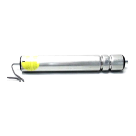
The RollerDrive EC310 can be used in both straight and curved sections and ensures a constant conveyor speed.
Motors, motor electronics and gears are installed in the RollerDrive.
Overload protection
The system has multiple overload protection systems:
Stall timing
If the RollerDrive is jammed and a start signal is issued, it will try to restart for a second every three seconds for
a total of a ten times. If the blockage is still present after these ten attempts, an error signal will be issued and the
RollerDrive will attempt to restart in a 60:1 cycle (where a restart is attempted for a second every 60 seconds) until
the blockage has been eliminated.
The RollerDrive will not be damaged if the system runs in stall timing mode for an extended period. The error signal is
reset if the RollerDrive begins running again at the selected speed or the start signal is cancelled.
Low speed
If a deviation from the selected speed of more than ±20% occurs for more than ten seconds, the RollerDrive is
reset if the RollerDrive begins running again at the selected speed or the start signal is cancelled.
Temperature monitoring
The temperature of the motor installed in the RollerDrive is monitored in addition to the temperature of the motor
issued. Once the overheated components have cooled down, the error signal will be reset.
If the RollerDrive cools down and the start signal is still active, the RollerDrive may start up again
unintentionally. Troubleshooting must be carried out via the control system.

16 of 42
Version 3.1 (02/2019)
Translation of the original operating manual
Product information
Holding brake (zero motion hold)
The RollerDrive EC310 is equipped with an electronic holding brake that allows it to be used in sloped and ascending
conveyors. For this, the RollerDrive is held in position if no start signal is issued. If the power supply system fails, the
Energy recovery system
The RollerDrive recovers energy when braking the conveyed material. This results in the motor and motor electronics
heating up less and improves the energy balance of the system. The Interroll controls are equipped with a circuit that
prevents an increase of voltage in the power supply.
If motor controls are used without a voltage limiter (brake chopper), it must be ensured that the power
supply units used are suitable for energy recovery.
3.3 Rating plate
RollerDrive as intended.
Rating plate
1 Manufacturer 5 Rated voltage
2 Date of manufacture 6 Speed range
3 Gear ratio 7 RollerDrive type
4 Output 8 Serial number

Version 3.1 (02/2019)
Translation of the original operating manual
17 of 42
Product information
3.4 Product identication
The following information is required to identify the RollerDrive:
Information Possible value Own value
RollerDrive
Rating plate
Motor type
Gear ratio
Serial number
Tube diameter 50 mm, 51 mm
Tube material Stainless steel
Zinc-plated steel
Chromium-plated steel
Aluminium
Tube sleeve PVC hose 2 mm, 5 mm
PU hose 2 mm
Rubber coating 2–5 mm
Tapered elements 1.8°, 2.2°
Roller installation length Installation length
Drive element PolyVee belt
Round belt:
Groove
Round belt head
Toothed belt
Attachment on the non-cable side Hexagonal spring shaft
Internal thread attachment
Hexagonal spring shaft, conical
(See „Dimensions of the bearing
housings on the non-cable side“ on
page 21)

18 of 42
Version 3.1 (02/2019)
Translation of the original operating manual
Product information
3.5 Technical specications
Rated voltage 24 V DC, protected extra-low voltage (PELV)
Voltage range 18 to 28 V DC
Idle current 0.4 A
Rated current Approx. 2 A 1)
Starting current Approx. 4 A 1)
Switching threshold, signal input
"Rotational direction"
Safe "High": U > 7 V DC
Safe "Low": U < 4 V DC
Mechanical power 32 W
Maximum residual ripple of the
power supply
3%
Maximum noise level
(mounted)
55 dB(A) 2)
Protection rate IP54 or IP66
Ambient temperature in operation EC310:
EC310 DF:
EC310 IP66:
0 °C to +40 °C
-30 °C to 0 °C
+5 °C to +40 °C
Ambient temperature for
transport and storage
-30 °C to +75 °C
Altitude of installation site Max. 1000 m 3)
All data applies for an ambient temperature of 20 °C.
From 25 °C, a derating factor must be taken into account.
1) The actual current course is dependent on the circumstances of the application, such as conveyor weight, number of
connected rollers, etc.
2)
3) Estimated derating: 5% from 1500 m, 10% from 2000 m.

Version 3.1 (02/2019)
Translation of the original operating manual
19 of 42
Product information
3.6 RollerDrive performance data
Gear
ratio
Speed
range
[m/s]
Rated
torque
[Nm]
Start-up
torque
[Nm]
Holding
torque
[Nm]
9:1 0.09 to 1.75 0.45 1.10 0.36
12:1 0.07 to 1.31 0.61 1.46 0.48
16:1 1) 0.05 to 0.98 0.81 1.95 0.64
20:1 1) 2) 0.04 to 0.78 1.01 2.44 0.80
24:1 1) 2) 0.03 to 0.65 1.21 2.92 0.96
36:1 1) 2) 0.02 to 0.44 1.82 4.38 1.44
48:1 1) 2) 0.02 to 0.33 2.42 5.85 1.92
64:1 1) 0.01 to 0.25 3.23 7.80 2.56
98:1 1) 0.01 to 0.16 4.84 11.69 3.84
1) EC310 IP66
2) EC310 DF
Before the run-in, the values can vary by up to ±20%. After the run-in phase, the values for 95% of all RollerDrives
used vary only in the range of ±10%.
3.7 Controls for the RollerDrive EC310
• DriveControl
• ZoneControl
• ConveyorControl
• MultiControl AI
More detailed information on the controls can be found in the respective operating manual, in the
"Conveyor rollers, RollerDrive, controls" Interroll catalogue or at www.interroll.com.

20 of 42
Version 3.1 (02/2019)
Translation of the original operating manual
Product information
3.8 RollerDrive connector
Pin Colour Function Value
1 Brown Input of the power supply (+) Rated voltage: 24 V DC
Voltage range: 18 to 28 V DC
2 White Input of the rotational direction as
seen from the end of the cable of the
RollerDrive
"Low" = anti-clockwise
"High" = clockwise
3 Blue Earth for power supply and signal (-) Earth
4 Black Error output Open collector
UCESAT = 0.5 V DC at IC= 5 mA
UMAX = 30 V DC
ICMAX = 5 mA
Error: "Low" signal
No error: "High" signal
5 Grey Analogue speed/start signal See table below
Analogue speed/start signal (pin 5)
Voltage range 0 to 24 V DC
Stop (zero motion hold) 0 to 2.3 V DC
Speed 2.3 V DC to 10 V DC
2.3 V = minimum speed
10 V = maximum speed
Max. speed 10 V DC to 24 V DC
The conveyor speed results from the gear ratio and the voltage rating of the analogue speed signal.
Other manuals for RollerDrive EC310
2
This manual suits for next models
4
Table of contents
Other Interroll DC Drive manuals
Popular DC Drive manuals by other brands
GFA
GFA ELEKTROMAT SI 25.35-30,00 installation instructions

YASKAWA
YASKAWA MECHATROLINK-III installation manual

Franklin
Franklin Q-link Installation, Programming Operation, & Maintenance Manual

ITOH DENKI
ITOH DENKI CB-016 series user manual

Rockwell Automation
Rockwell Automation Allen-Bradley PowerFlex 755T Series installation instructions

Calpeda
Calpeda EASYMAT 5MM Original operating instructions