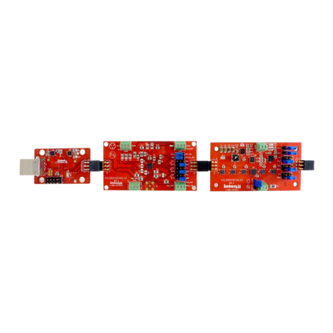
7AN1176.0
June 20, 2005
2. Error Message
3. PC just will not recognize the USB_RTC board If this
happens and all methods described above haven’t
helped, then uninstall the drivers using the FTDI uninstall
program (see the Installation Manual on the CD). Then
install the drivers again and check for proper operation.
Suggested RTC Tests
ISL1208 or ISL1209
1. Set time of day and turn on time and temperature
recorder Board can now be exposed to temperature,
shock, or other environmental influences to determine
effects on time accuracy. Main VCC can be turned on and
off to determine backup mode accuracy. Note that the
motherboard devices are only rated for commercial
temperature range (0°C to 70°C), but the RTC crystal is
good for full -40°C to +85°C. If wide temperature range
testing is desired, then the daughtercard can be placed in
a chamber with remote wiring from the motherboard to
the daughtercard. Consult the schematics for the boards
for any details on the connections.
2. Test the frequency output (FREQ) Go to register 08h
(INT) and set bits 0 to 3. Note that the LED D1 will
illuminate or flash to indicate FREQ is active (or alarm
has occurred). This LED will go off if the VCC is shut
down. The jumper JP2 will allow connection to an
external pullup or separate board for other tests. Note
that a ground connection will be required as well,
available at the motherboard (J3). Be careful with low
external pullup values (<10kΩ) as the decoupling on the
daughtercard may allow large voltage dips when the
open drain output is turned ON.
3. Test the temperature compensation feature Do a
temperature test as in #1, but enable the Temperature
Compensation function as described previously in the
instructions. The sliders can be used to set the value of
the ATR registers, and then those settings are saved by
clicking the Save button, then clicking to Enable
Temperature Compensation button. Note that it will take
many days to see small drifts of time with temperature,
but if a frequency counter is available a frequency test
can be done as the temp changes. Enable the frequency
output as in #2. Add a pullup resistor (10k or higher
advised) from JP2, pin 2 (daughtercard) to VCC
(available at the shunt of JP1, motherboard). The counter
can then be connected to the JP2-2 connection and
ground, and the absolute frequency monitored on the
counter. For best results it is suggested to use the 1.0Hz
frequency selection and use seven or more digits of
counter resolution to get one PPM of accuracy.
4. Test the ICC An ammeter can be connected in series with
the JP1 terminals to monitor the VCC supply current to
the device. Note that when using the software and polling
is enabled, the ICC will increase and vary quite a bit when
the serial interface is communicating.
5. Test the backup supply current, IBAT An ammeter can
be connected between the terminals of the backup
source and the VBAT input on JP2 of the motherboard.
Only one source may be selected at a time, so the shunt
needs to be removed when doing this. Click on the
normally closed switch icon in the menu bar to disconnect
VCC, then monitor the IBAT current.
6. Talk to an RTC device on a remote board Use the
motherboard connector pins and jumper wires to enable
communications with an RTC device on a separate test
board. The SDA, SCL and ground pins are mandatory for
this, and the test board Vcc should match the
motherboard Vcc within 5% for best results.
lSL1209 Only
The ISL1209 eval board provides event-detection functions
and includes special pins for external circuitry.
1. Test the event detection function The on-board switch
can be tested by connecting a shunt from the EVT to the
GND pins on J3 of the ISL1209 daughtercard. Then open
the Event Detection window by clicking on the pushbutton
switch icon in the menu bar, and enable event detection.
Any touch of the event detect switch will result in a
recorded event. Manually setting event-detect function
and options can also be done by writing to register 09h.
Please see the ISL1209 data sheet for details on event
detection options.
2. External event detection switches Since the switch
function is a Normally Closed (NC) function, external
circuits must use a break in the circuit to cause a
recorded event. Such breaks are possible using foil with
wire contacts inside of an enclosure or on a door frame.
Note that a long wire return is required on the door itself.
For simple switch circuits such as these, remove the
shunt from J3, and run wires from J2 to the external
switch.
3. External event detection circuits Since the ISL1209
Event Input is triggered by a low to high transition, and
the internal pullups can be disabled, external comparator
circuits can be used to trigger an event. Such circuits can
detect light or darkness, sound, movement, or
temperature limits. The connector J3 has and event input
pin, as well as VCC and VBAT supply pins, a ground pin
and a 10MΩpulldown to ground. These signals can be
jumpered over to another board to enable event detection
circuits that run from VCC or VBAT
, and can remotely
trigger the event pin.
Application Note 1176
