INTERSPIRO S9 User manual

ENGLISH
S9 and S9 Incurve
User Manual
32570H01

2
Copyright © 2018 Interspiro
This publication contains or refers to proprietary information which is protected by copyright. All
rights are reserved. Interspiro® and Divator® are registered trademarks belonging to Interspiro.
This publication may not be copied, photocopied, reproduced, translated, or converted to any elec-
tronic or machinereadable form in whole or in part, without prior written approval from Interspiro.

3
USER MANUAL...................................................................................4
CAUTIONS AND LIMITATIONS .......................................................................................5
CAUTIONS & LIMITATIONS OF USE FOR CBRN SCBA .....................................................5
IMPORTANT INFORMATION TO USER ............................................................................7
1 TECHNICAL DESCRIPTION.......................................................................................8
2 PREPARATIONS FOR USE.......................................................................................17
3 UNDERSTANDING THE S9 HUD, DDU AND BAC....................................................23
4 LEAKAGE AND FUNCTION TEST ...........................................................................26
5 DONNING ..........................................................................................................27
6 DURING USE ........................................................................................................31
7 DOFFING ..........................................................................................................36
8 TELEMETRY FUNCTIONS - CONFIGURATION .........................................................37
9 TRACKING FUNCTIONS - CONFIGURATION .........................................................41
10 CLEANING AND MAINTENANCE..........................................................................42
11 SPIROGUIDE ELECTRONICS CONFIGURATION AND PASS DATA LOGGING ...........48

4
S9 AND S9 INCURVE
USER MANUAL
WARNING!
Before use of S9 and S9 Incurve SCBA in an emergency/rescue situation, the user
must have been given proper training in its use, have read and understood this User
manual and demonstrated prociency to a responsible teacher or supervisor. Failure
to do so can result in injury or death for the user and can have serious consequences
for people to be rescued and/or items of value to be saved.
INTERSPIRO’S LIMITED WARRANTY
INTERSPIRO WARRANTS THIS PRODUCT AGAINST FAILURE TO COMPLY WITH INTERSPIRO’S PUBLISHED
SPECIFICATIONS FOR THE PRODUCT AND AGAINST DEFECTS IN MATERIALS AND WORKMANSHIP FOR A
PERIOD OF TWELVE (12) MONTHS AFTER DATE OF PURCHASE. WITHIN THAT PERIOD, INTERSPIRO WILL, AT ITS
OPTION, REPAIR OR REPLACE THE PRODUCT OR REFUND YOUR PURCHASE PRICE IF INTERSPIRO DETERMINES
THE PRODUCT DOES NOT CONFORM TO INTERSPIRO’S SPECIFICATIONS OR IS DEFECTIVE IN MATERIAL OR
WORKMANSHIP.
TO MAKE A WARRANTY CLAIM, CONTACT YOUR AUTHORIZED INTERSPIRO DISTRIBUTOR OR INTERSPIRO
DIRECTLY. FOR TELEPHONE INQUIRIES PLEASE HAVE YOUR PRODUCT INVOICE OR OTHER PROOF OF PURCHASE
AVAILABLE. IF YOU WRITE, INCLUDE PROOF OF PURCHASE AND A WRITTEN EXPLANATION OF THE PROBLEM.
WARRANTY SERVICING WILL BE PROVIDED ON-SITE OR AT ONE OF INTERSPIRO’S AUTHORIZED SERVICE
FACILITIES, AT INTERSPIRO’S DISCRETION. IF SHIPMENT TO AN AUTHORIZED SERVICE FACILITY IS REQUIRED,
SHIPPING INSTRUCTIONS WILL BE PROVIDED BY INTERSPIRO OR YOUR AUTHORIZED INTERSPIRO DISTRIBUTOR.
DO NOT SHIP ANY PRODUCT OR COMPONENT WITHOUT SHIPPING AUTHORIZATION. ALL SHIPPING CHARGES
TO INTERSPIRO’S SERVICE FACILITY MUST BE PREPAID BY THE CUSTOMER.
THIS LIMITED WARRANTY DOES NOT APPLY IF THE PRODUCT HAS BEEN (I) INVOLVED IN AN ACCIDENT OR
SUBJECTED TO MISUSE, IMPROPER MAINTENANCE OR NEGLIGENCE; (II) ALTERED OR REPAIRED IN ANY WAY
THAT HAS, IN INTERSPIRO’S JUDGEMENT, ADVERSELY AFFECTED ITS PERFORMANCE OR RELIABILITY; (III) USED IN
AN APPLICATION OR FOR A PURPOSE FOR WHICH THE PRODUCT WAS NOT DESIGNED OR UNDER STRESSES
OR CONDITIONS EXCEEDING THOSE SPECIFIED FOR THE PRODUCT; OR (IV) DAMAGED AFTER LEAVING
INTERSPIRO’S FACILITY.
THIS LIMITED WARRANTY IS VALID ONLY FOR THE ORIGINAL PURCHASER, AND IS NOT TRANSFERABLE.
IMPORTANT! THIS LIMITED WARRANTY IS EXCLUSIVE AND IS IN LIEU OF ALL OTHER WARRANTIES, EXPRESSED
OR IMPLIED, INCLUDING ANY WARRANTY OF MERCHANTABILITY OR FITNESS FOR A PARTICULAR PURPOSE.
INTERSPIRO DISCLAIMS ALL OTHER LIABILITIES AND OBLIGATIONS, INCLUDING, TO THE EXTENT ALLOWED
BY LAW, NON-CONTRACTUAL LIABILITY FOR PERSONAL INJURY OR PROPERTY DAMAGE BASED UPON ITS
NEGLIGENCE, STRICT LIABILITY OR ANY OTHER GROUND. TO THE FULL EXTENT ALLOWED BY LAW, AND
REGARDLESS OF WHETHER LIABILITY IS ASSERTED ON THE BASIS OF BREACH OR WARRANTY, NEGLIGENCE,
STRICT LIABILITY, BREACH OF CONTRACT OR OTHERWISE, INTERSPIRO SHALL NOT BE RESPONSIBLE FOR SPECIAL,
INCIDENTAL, CONSEQUENTIAL OR PUNITIVE DAMAGES, INCLUDING LOSS OF PROPERTY, LOSS OF PROFITS OR
REVENUES, DOWN-TIME COSTS AND THE COST OF SUBSTITUTE EQUIPMENT (SOME STATES DO NOT ALLOW THE
EXCLUSION OR LIMITATION OF INCIDENTAL OR CONSEQUENTIAL DAMAGES, SO THE ABOVE LIMITATION MAY
NOT APPLY TO YOU).
THIS WARRANTY GIVES YOU SPECIFIC LEGAL RIGHTS, AND YOU MAY ALSO HAVE OTHER RIGHTS WHICH VARY
FROM STATE TO STATE.

5
CAUTIONS AND LIMITATIONS
J. Failure to properly use and maintain this product could result in injury or death.
M. All approved respirators shall be selected, tted, used, and maintained in
accordance with MSHA, OSHA, and other applicable regulations.
N. Never substitute, modify, add, or omit parts. Use only exact replacement parts in
the conguration as specied by the manufacturer.
O. Refer to users instructions, and/or maintenance manuals for information on use
and maintenance of these respirators.
S. Special or critical users instructions and/or specic use limitations apply. Refer to
instruction manual before donning.
CAUTIONS & LIMITATIONS OF USE FOR CBRN SCBA
Q. Use in conjunction with personal protective ensembles that provide appropriate
levels of protection against dermal hazards.
R. Some CBRN agents may not present immediate effects from exposure, but can
result in delayed impairment, illness, or death.
T. Direct contact with CBRN agents requires proper handling of the SCBA after each
use and between multiple entries during the same use.
U. Decontamination and disposal procedures must be followed. If contaminated with
liquid chemical warfare agents, dispose of the SCBA after decontamination.
S - SPECIAL OR CRITICAL USER’S INSTRUCTIONS
Approved for respiratory protection during entry into or escape from oxygen decient
atmospheres, gases, and vapors at temperatures above -25 degrees F (-32 degrees C).
The S9 and S9 Incurve LCD of the Digital Display Unit (see section 3.2) is not functional
if the S9 SCBA is stored prior to use at -25 degrees F (-32 degrees C). The red and
black buttons on the Digital Display Unit (DDU) controlling the PASS functions and the
LEDs in the DDU indicating PASS mode (see sections 6.1-6.3) are fully functional if the
S9 SCBA is stored at -25 degrees F (-32 degrees C). The LCD of the S9 SCBA DDU
functions if the S9 SCBA is stored prior to use at -13 degrees F (-25 degrees C).
Approved only when compressed air reservoir is fully charged with air meeting the
requirements of the Compressed Gas Association Specication G-7-1 for Type 1, Grade
D air or higher quality, as well as meeting a dew point level of -65°F (-54°C) or dryer
(24 ppm v/v or less), and a maximum particulate level of 5 mg/m3 air. The breathing
air quality must be in accordance with NFPA 1989, Standard on Breathing Air Quality
for Fire and Emergency Services Respiratory Protection. The container shall meet
applicable DOT specications.
S9 and S9 Incurve models that include an integrated PASS are only approved for use
as an integrated SCBA/PASS system.
If the PASS is not fully functional the S9 and S9 Incurve SCBA must be removed from
service.

6
EMERGENCY BREATHING SAFETY SYSTEM (EBSS) SPECIAL OR CRITICAL
USER’S INSTRUCTIONS:
• Activation or engagement of EBSS in either the donor or receiver mode changes
the SCBA use to Escape-Only, approved service time for either the donor, or the
receiver is no longer applicable.
• Entry approval only restored after re-charge, either host or donor.
• EBSS may not be engaged or activated in donor mode after the donor End-of-
Service-Time-Indicator (EOSTI) has activated.
• Immediately after the EBSS connection has been completed, the cylinder valve of
the receiving SCBA shall be closed.
• Users must be fully trained in the operation of EBSS in accordance with a training
program conforming to the requirements of NFPA Standards 1404, Fire Service
Respiratory Protection Training and 1500, Fire Department Occupational Safety
and Health Program.
• Simultaneous connection of more than two users, one donor and one receiver, is
not permitted.
• Not suitable for connection in CBRN environment.
END-OF-SERVICE-TIME-INDICATOR (EOSTI) 33% SET POINT
INFORMATION:
NFPA 1981, 2019 and NIOSH 42 CFR Part 84 require the set point for the EOSTIs
to be 35 % ±2 % of full cylinder pressure. The S9 EOSTI 33% (low air alarm whistle)
and the HUD EOSTI are set at 35 % ±2 %. The S9 remote analog pressure gauge
EOSTI indication is marked with a 1/3 fraction and is marked in red from 1/3 to
Empty.

7
IMPORTANT INFORMATION TO USER
Please read this information carefully before referring to the apparatus instructions.
The S9 and S9 Incurve breathing apparatus should only be used by adults in good
physical and physiological condition.
The S9 and S9 Incurve SCBA must be used in a manner consistent with NFPA 1500,
Standard on Fire Department Occupational Safety and Health Program.
The face mask may not seal properly with your face if you have a beard, heavy
sideburns or other physical characteristics interfering with the mask’s contour.
An improper facial seal may allow non-respirable air to leak into the mask, reducing
or eliminating respiratory protection. The seal must be tested before each use.
Before occupational use of this respirator a written respiratory protection program
must be implemented meeting all the local government requirements. In the United
States employers must comply with OSHA 29 CFR 1910.134 which includes medical
evaluation, training, and t testing.
OSHA 1910.134 requires that before any employee uses a positive pressure tight-
tting facepiece, they must pass an appropriate qualitative or quantitative t test
initially and at least annually thereafter.
Do not use S9 and S9 Incurve in an emergency/rescue situation unless you have
received proper training in its use, have read and understood this Instruction manual
and demonstrated prociency to a responsible teacher or supervisor. Special attention
must be given to:
• face seal
• test before use
• awareness of different durations at different conditions
• emergency situation (loss of air and free air ow)
• procedure at low-air alarm.
Note: This equipment has been tested and found to comply with the limits for a
Class A digital device, pursuant to part 15 of the FCC Rules. These limits are
designed to provide reasonable protection against harmful interference when the
equipment is operated in a commercial environment. This equipment generates,
uses, and can radiate radio frequency energy and, if not installed and used in
accordance with the instruction manual, may cause harmful interference to radio
communications. Operation of this equipment in a residential area is likely to cause
harmful interference in which case the user will be required to correct the interference
at his own expense. Operation is subject to the following two conditions: (1) this
device may not cause interference, and (2) this device must accept any interference,
including interference that may cause undesired operation of the device.
Only holders of a valid INTERSPIRO Service Certicate may service and test S9 and
S9 Incurve apparatus.
Failure to comply with these special points can result in respiratory
injury or death for the user and may have serious consequences for
people to be rescued and/or items of value to be saved.

8
1 TECHNICAL DESCRIPTION
The S9 and S9 Incurve is a compressed air breathing apparatus for work in a
contaminated environment. The apparatus consists of:
• A harness assembly
• An air supply cylinder
• A face mask with breathing valve and by-pass including:
-A wireless Heads-Up Display (HUD) inside the face mask
• A regulator unit including:
-A Breathing apparatus computer (BAC)
-A Digital Display Unit (DDU)
-A Rapid Intervention Crew/Company Universal Air Connection System (RIC UAC)
-An integrated Personal Alert Safety System (PASS)
-Optional tracking senders
-Optional telemetry unit
• An extra air/rescue hose connection
The S9 and S9 Incurve self contained breathing apparatus (SCBA) uses clean dry air
compressed in a cylinder, carried on the back. The air is fed to a pressure regulator
which reduces the cylinder air pressure to a secondary pressure of approximately 110
psi. The air is then supplied to the face piece through the mask mounted breathing
valve.
The breathing valve is of the pressure-demand type that releases air on inhalation.
The S9 and S9 Incurve operates with positive pressure which keeps toxic gases from
leaking into the facepiece. Even if leakage was to occur, the positive pressure keeps
surrounding air out of the mask, although under such conditions duration of the air
supply may decrease.
A primary audible low air warning device placed at the pressure gauge / DDU is
located at the left shoulder in front of the user. A wireless Heads-Up Display (HUD)
installed inside the face mask acts as a visual pressure gauge and also provides a
secondary visual low air warning at both 1/2 and 1/3 cylinder pressure. The HUD
allows both the cylinder pressure and the visual low air warning to always be in the
wearer’s eld of vision. The HUD also includes a low battery indicator.
The apparatus is equipped with a Personal Alert Safety System (PASS) which is an
integrated PASS unit designed to meet the NFPA 1982 Standard on PASS for Fire
Fighters 2018 Edition. The PASS unit is integrated into the SCBA and is automatically
activated by air pressure from the SCBA. Tracking system and telemetry system can be
installed as an option.
1.1 HARNESS ASSEMBLY
The S9 incorporates a unique double pivoting padded harness assembly. The heavily
padded harness includes a rescue/carrying handle. Chest strap and a buddy
breathing hose pouch are optional features.
The harness can be adjusted for different body sizes by changing the distance
between the hip belt and the shoulder harness. The height adjustment can be made
with cylinder mounted on the SCBA.

9
1.2 INCURVE HARNESS
An alternate S9 Incurve harness is also available. The S9 Incurve harness is the same
as the padded harness with the pneumatics mounted on the same backframe. The
difference being the Incurve harness includes a minimum of textile parts making the
Incurve harness easy to clean, robust and light weight - without compromising comfort.
1.3 AIR SUPPLY
The compressed air supply utilize lightweight aluminum/composite cylinders wrapped
in berglass, kevlar glass or carbon ber available in 30, 45 and 60 minute
duration*.
The cylinders are tted with a valve which includes a built-in pressure gauge. The
cylinder valve is equipped also with a burst disc, designed to rupture and let air out if
the cylinder should be inadvertently overcharged.
CAUTION! SHOULD THE CYLINDER BE EXPOSED TO A PRESSURE THAT CAUSES THE BURST DISC TO RUPTURE, IT
MUST BE RETURNED TO AN AUTHORIZED SPIROMATIC S SERVICE CENTER FOR INSPECTION AND REPAIR.
Duration* Charging pressure psi Approx. content of. free air in cu. ft
60 min. 4500 87
45 min. 4500 66
30 min. 4500 45
30 min. 2216 45
* Duration tested to NIOSH standards.
LIMITATION! APPROVED ONLY WHEN COMPRESSED AIR RESERVOIR IS FULLY CHARGED WITH AIR MEETING THE
REQUIREMENTS OF THE COMPRESSED GAS ASSOCIATION SPECIFICATION G-7-1 FOR TYPE 1, GRADE D AIR
OR HIGHER QUALITY, AS WELL AS MEETING A DEW POINT LEVEL OF -65°F (-54°C) OR DRYER (24 PPM V/V OR
LESS), AND A MAXIMUM PARTICULATE LEVEL OF 5 MG/M3 AIR. THE CONTAINER SHALL MEET APPLICABLE DOT
SPECIFICATIONS.
CAUTION! DURATION IS DEPENDENT ON THE USER’S EXERTION, PHYSICAL AND EMOTIONAL CONDITION, AS
WELL AS ON ENVIRONMENTAL PRESSURE AND WHETHER THE CYLINDER WAS FULLY CHARGED AND WHETHER
THE FACEPIECE FITS. DURATION CAN VARY 50 % OR MORE.
10
1.3 FACE MASK
The outer and inner masks are made from a specially compounded rubber material to
ensure a high degree of resistance to ozone ageing and acceptability to the wearer.
The mask is equipped with a large, easily replaceable visor which is held in place
by two half frames and two screws. The S9 mask includes a visor meeting the Lens
Radiant Heat Resistance Performance and Elevated Temperature Heat and Flame
Resistance Performance requirements of NFPA 1981-2019. The S9 mask is available
with either a fabric head harness or a rubber head harness. The face piece also has
provisions for tting spectacles.
A speech diaphragm is mounted within the inner mask with a direct outlet to outside
the mask to ensure the best possible communication. In addition, an inner cone over
the speech diaphragm enhances the speech diaphragm performance. As a further
enhancement to speech reproduction an external speech cone is tted which also acts
as a positive security lock for the breathing valve.
The S9 mask is available in four sizes: SMALL, MEDIUM, LARGE, and EXTRA LARGE.
The standard size facemask is the LARGE size.
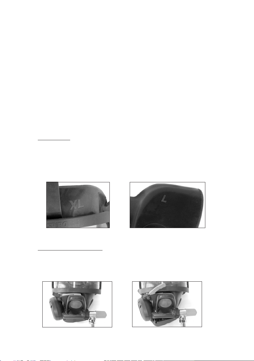
Size markings:
• The SMALL mask is marked “S” on the outer mask and “M” on the inner mask.
• The MEDIUM mask is marked “M/L” on the outer mask and “M” on the inner mask.
• The LARGE mask is marked “M/L” on the outer mask and “L” on the inner mask.
• The EXTRA LARGE mask is marked “XL” on the outer mask and “L” on the inner
mask.
Size marking on outer mask Size marking on inner mask
AMBIENT AIR HATCH MASK
Positive pressure is activated by closing the ambient air hatch by pushing the
exhalation valve cover against the face mask. To shut off positive pressure and
breathe ambient air, simultaneously press down the indicator arm and push the
exhalation valve cover away from the face mask.
Activated positive pressure Ambient air mode

11
FIRST BREATH MASK
Positive pressure is automatically activated by the rst breath and can be switched off
manually by pushing the lifting arm on the breathing valve away from the diaphragm
cover.
Activated positive pressure Positive pressure switched off
1.4 BREATHING VALVE AND BY-PASS VALVE
The SPIROMATIC S breathing valve has a “plug-in” connection to connect it to the
face mask. The outer speech cone locks the breathing valve into position. This feature
provides a safe positive connection between the face mask and breathing valve and
prevents accidental disconnection.
The by-pass valve overrides the normal automatic function of the pressure demand
valve. When the by-pass valve is opened the air will free ow into the mask. To open
the valve turn the red knob counter clockwise. To close the valve turn the red knob
fully clockwise.
NOTE! WHEN THE BY-PASS VALVE IS OPEN THE DURATION TIME WILL BE SHORTER. WHEN THE BY-PASS VALVE IS
OPERATED THE WEARER SHOULD ABORT ANY OPERATION AND RETURN TO AN AREA OF RESPIRABLE AIR.
1.5 REGULATOR ASSEMBLY WITH RIC UAC
The pressure regulator used in the S9 and S9 Incurve models is a balanced piston
pressure reducer with an extremely high ow capacity. The very high capacity ensures
that the positive pressure is maintained in the mask even at low cylinder pressures and
at extremely high breathing rates.
The regulator unit is of a “plug in” type which means that it is pushed into a manifold
and locked in place with a locking clip and cover. This modular system enables
simple servicing to be carried out with minimum down time for the apparatus by using
service exchange of modular components.
12
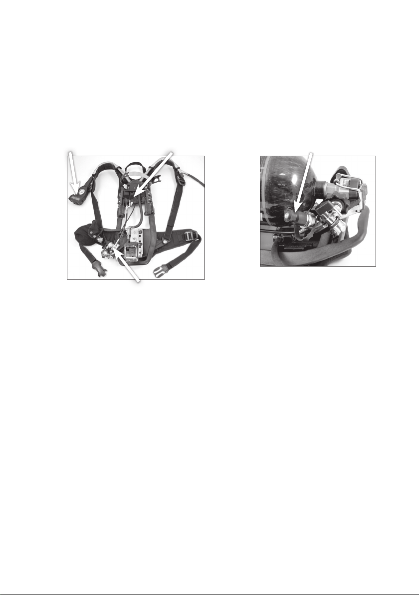
The manifold assembly is comprised of a regulator manifold with a handwheel
connector for the cylinder valve, a particle lter, and a high pressure Rapid
Intervention Crew/Company Universal Air Connection System (RIC UAC).
The RIC UAC will permit replenishing the breathing air cylinder of an SCBA user to be
replenished from an independent rescue breathing air supply source while the SCBA
victim remains trapped or unable to be removed from the hazardous atmosphere.
The S9 is equipped with a supplied air connector that is conveniently placed on the
right shoulder. This makes connection of air line hoses and accessories easy for the
user.
RIC UAC
connection
BAC
Manifold
assembly
DDU

13
1.6 SPIROGUIDE ELECTRONICS PACKAGE INCLUDING BAC, HUD AND
DDU
The SpiroGuide electronics package consists of:
• Breathing Apparatus Computer (BAC)
• Digital Display Unit (DDU)
• Wireless Heads-Up Display (HUD)
The BAC is a computer unit and pressure sensor mounted in the backplate. It is
powered by 6 AA batteries.
The wireless HUD is a combination pressure gauge and electronic low air warning
device. It also indicates PASS Pre-Alert mode and PASS Alarm mode. The HUD is
installed in the face mask.
The BAC and HUD will link together based on an address code received from each
other. The BAC and HUD to be used together must linked before use, following the
procedure in section 2.7. When the BAC is started it will only connect to the HUD it
previously has been linked to.
The HUD includes a light sensor to measure the ambient light. The brightness of the
LEDs is automatically adjusted according to the ambient light conditions. The pressure
indication displayed in the HUD is refreshed every 2 seconds. The HUD is powered
with 2 AAA batteries.
The DDU is located on the left shoulder with the mechanical pressure gauge and
mechanical whistle. The DDU is connected with a cable to the BAC. It is powered
from the BAC and has no batteries.
The motion sensor for the integrated PASS and the sensor for measuring absorbed
temperature are both located in the display unit.
The BAC, HUD and DDU activates when the SCBA cylinder valve is opened.
1.7 AUDIBLE AND VISUAL LOW AIR WARNINGS
The S9 and S9 Incurve is equipped with dual redundant low air warning End of
Service Time (EOST) indicators.
The primary low air alarm (EOST) is an audible mechanical whistle. The secondary
alarms (EOST) indicators are visual ashing yellow and red LED’s on the HUD.
Audible Warning and Pressure Gauge
When the primary air supply pressure has dropped to approximately 33 % the
audible alarm will start to sound. An analog pressure gauge is located along with
the audible mechanical whistle on the left shoulder in front of the user. An optional
secondary audible electronic low air warning is available. The sounders for the
electronic low air alarm, when activated, are located on both sides of the BAC. The
electronic low air warning also has an optional mutable function depending of the
preference of the Fire Department. If mutable, the electronic low air warning will be
silenced for 10 seconds by pressing the backlight button on the DDU (see section
3.2).
The DDU pressure gauge is a secondary pressure gauge.

14
HUD Visual Pressure Gauge and Visual Warning, BAC and DDU Visual Warning
A wireless Heads-Up Display (HUD) inside the face mask acts as a secondary visual
pressure gauge and also provides visual low air warnings at both 1/2 and 1/3
cylinder pressure. Flashing yellow and red LED’s will activate when the primary air
supply pressure has dropped to approximately 50% and the ashing red LED only at
approximately 33%. The visual ashing red LED will continue to ash until the cylinder
content is depleted and the unit is switched off.
Flashing red LEDs are also activated on the BAC and the Digital Display unit at 1/3
cylinder pressure for other reghters to see.
1.8 INTEGRATED PASS
The PASS is automatically activated by air pressure from the SCBA and put into
Sensing mode. The unit may be put into Alarm from Sensing mode at any time by
pressing the red alarm button on the DDU.
When in Alarm the unit may be reset to the Sensing mode by pressing the black
backlight button two times or by rst pressing and holding the black backlight button
and then simultaneously pressing the red alarm button on the DDU.
The unit may be turned Off by closing the cylinder valve, evacuating air from the
system and then by pressing the black backlight button two times or pressing and
holding the black backlight button and then simultaneously pressing the red alarm
button on the DDU.
The internal data logging records dates and times including:
• Power On
• Pre-Alert and Lack of Motion Alarm
• Manual Alarm
• Reset
• Power Off
• Low Battery Warnings.
The data log information can be downloaded to a PC using the data log transfer
software “InMode” and a USB dongle. Contact Interspiro for additional information.
The PASS can be used without having the SCBA pressurised and is activated by
pressing the red alarm button on the DDU. This will activate the PASS and start the
Alarm mode, reset the PASS by pressing the black backlight button two times or by
pressing and holding the black backlight button and then simultaneously pressing the
red alarm button on the DDU. The PASS is now in Sensing mode.

15
1.9 OPTIONAL CYLINDER QUICK COUPLING
The SCBA can be equipped with a cylinder quick coupling as an option. The
regulator unit is then connected to the cylinder valve by simply pushing them together.
When the SCBA is pressurised the quick coupling is locked and not possible to
disconnect. With the SCBA evacuated of air the quick coupling can be disconnected
by pushing the locking ring and then removing the regulator unit from the cylinder
valve.
The quick coupling ts 4500 psi cylinders with the use of an adaptor on the cylinder
valve. The adapter is installed on the cylinder valve with a torque of 40 Nm (29.5 lb
ft).
Cylinders with the adapter can be re-lled without removing the adapter. Interspiro
offers a quick connect cylinder charging adapter, p/n 31602-01, for existing ll
hoses.
If the adapter is removed the cylinder can be lled with a standard ll hose.

16
1.10 SAFETY CERTIFICATIONS
NIOSH 42 CFR Part Approved and NIOSH CBRN SCBA Approved.
Safety Equipment Institute (SEI) certied according to NFPA 1981, 2019 Edition and
NFPA 1982, 2013 Edition.
Certied Intrinsically Safe: UL 913, for use in Class 1, Division 1, Group A, B, C, and
D Hazardous Locations.
-INTRINSICALLY SAFE SECURITE INTRINSEQUE PER UL Std. 913 Class I, II, II DIV.1
Gr. A-G CONFORMS TO CAN/CSA C22 No. 157-92. EExiaIIC T4
-FCC ID: 0A3MRF24J40MA
“Warning - substitution of components may impair intrinsic safety.”
PASS is designed to meet the design and performance requirements for personal
alert safety systems (PASS) to be used by re ghters engaged in rescue, re ghting
and other hazardous duties as dened in the NFPA 1982 Standard on PASS for Fire
Fighters 2018 edition.
Certifying Agency Contact Information:
NIOSH and/or SEI can be contacted to report any operational malfunctions.
National Institute for Occupational Safety and Health (NIOSH)
Phone: 800-CDC-4636
Safety Equipment Institute (SEI)
1307 Dolley Madison Blvd. Suite 3A
McLean, VA 22101
Phone (703) 442-5732 Fax (703) 442-5756
Interspiro contact information to report any operational malfunctions:
Interspiro Inc
Phone: 262-947-9901 Fax: 262-947-9902

17
2 PREPARATIONS FOR USE
2.1 BATTERY INSTALLATION / REPLACEMENT
To reduce the risk of ignition of a ammable atmosphere, batteries must only be
changed in an area known to be non-hazardous.
WARNING! CHANGE BATTERIES ONLY IN A NON-HAZARDOUS AREA.
Immediate replacement of the batteries is necessary when the low battery alarm has
activated. The Low Battery Alarm will activate when the batteries reach a level of
approximately 2 hours of operating time remaining. INTERSPIRO, Inc. assumes no
liability for mechanical, electrical or other types of battery failure.
Do not mix battery manufacturers or old with new batteries.
2.2 BAC BATTERY INSTALLATION / REPLACEMENT
Always use the specied Duracell Procell MN1500 AA alkaline batteries.
Unscrew the screw securing the battery lid with a phillips screwdriver. Open the
battery lid and remove the batteries. Insert three new AA batteries oriented according
to the markings on the battery compartment. Close the battery lid and tighten the
screw of the battery compartment moderately, a beep will indicate that the batteries
are positioned correctly.
Repeat the procedure with 3 AA batteries for the battery compartment on the other
side.
2.3 HUD BATTERY INSTALLATION / REPLACEMENT
Always use the specied Duracell MN2400 or Energizer E92 AAA alkaline batteries.
The HUD must be installed in the re ghter’s face mask so that it is protected from
electrostatic charging when in use.
Remove the HUD from the face mask to allow access to the batteries in the two sides
of the HUD.
Unscrew the screw securing the battery cover with a phillips screwdriver.

18
Lift up the locking tab and open the battery compartment cover. Insert the AAA
battery oriented according to the marking on the HUD. Close the cover and install
the screw. Gently tighten for even gasket pressure ensuring a good seal. Do not over
tighten the screw. Repeat for the second battery on the other side.
When closing the battery compartment the HUD will ash all LEDs two times.
2.4 HARNESS ADJUSTMENT
The harness should be adjusted to ensure that the majority of the weight is carried
on the hip, not on the shoulder. To accommodate for different body sizes the height
of the harness can be adjusted by altering the distance between the hip belt and the
shoulder harness.
To adjust the harness push the two red buttons located beneath the hip belt together.
Slide the hip belt up or down until it clicks into the correct position.
There are four different positions, S, M, L and XL. The selected position is indicated
with red squares next to the letters “S”, “M”, “L” and “XL” engraved in the backplate.
The size indication is visible from both sides of the harness.
The height adjustment can be made with cylinder mounted and also with SCBA
installed in a re truck.
2.5 MOUNTING THE CYLINDER
1. Make sure the hoses are routed correctly according the picture. In the correct
position the raised area showing “INTERSPIRO” on the hose connector is visible
in the cut out of the locking plate. Secure the locking plate by tightening the
screw.
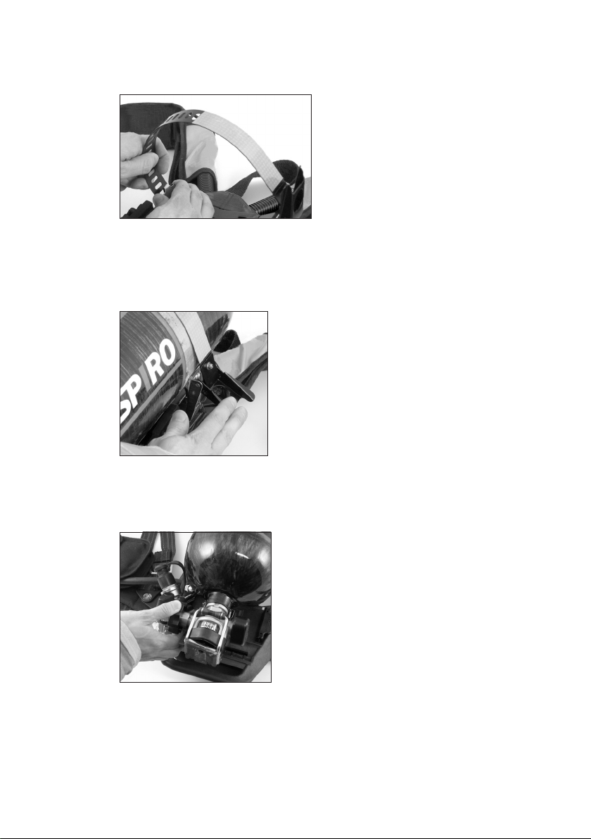
19
2. Open the toggle link on the harness and check that the strap loop is big enough
for the cylinder to be used. If not, press the small locking hook and enlarge the
diameter of the loop.
3. Slide the cylinder into the strap loop and push it in until the valve snaps into its
holder and locks (The cylinder valve connection thread should be on the opposite
side of the toggle link). Adjust the strap loop by pushing the strap into the guide
plate until it ts snugly around the cylinder making sure that the hook on the side
engages in one of the oblong holes.
4. Close the toggle link.
FOR VERSION WITH HAND WHEEL CONNECTOR:
5. Connect the regulator unit to the cylinder valve. Tighten the handwheel connector
by hand.
20
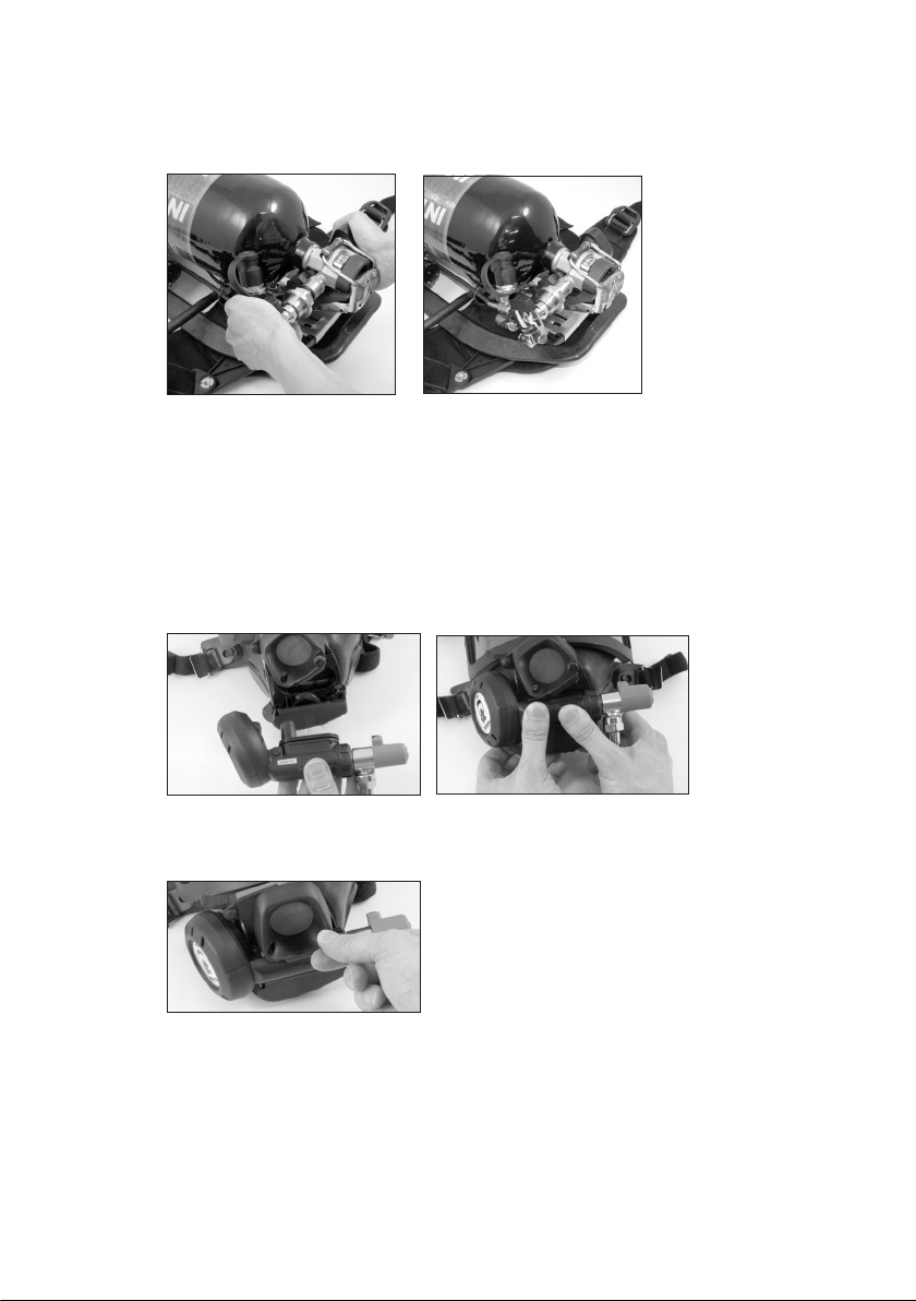
FOR VERSION WITH CYLINDER QUICK COUPLING:
5. Align the quick coupling in the regulator unit with the quick coupling adapter on
the cylinder valve. Push the regulator unit together with the cylinder valve until it
“clicks” into position.
FOR BOTH VERSIONS:
6. Check that the hoses are positioned correctly with the RIC tting pointing upward
and positioned against the cylinder.
2.6 CONNECTING THE FACE MASK
1. Insert the breathing valve into the face mask with the diaphragm housing on the
right hand side of the mask as worn. Make sure not to push on the internal speech
diaphragm when inserting the breathing valve.
2. Lock it into position by sliding down the outer speech cone and tighten the screw
by hand. In the correct position the serial number on the breathing valve is
covered by the lip of the speech cone.
This manual suits for next models
1
Table of contents
Other INTERSPIRO Safety Equipment manuals


Popular Safety Equipment manuals by other brands

Lanex
Lanex PB-20 instruction manual

SKYLOTEC
SKYLOTEC ANCHOR ROPES Instructions for use

Besto
Besto Buoyancy Aid 50N Instructions for use

TEUFELBERGER
TEUFELBERGER NODUS Manufacturer's information and instructions for use

Troy Lee Designs
Troy Lee Designs Tbone Product owners manual

Innova
Innova Xtirpa Instruction and safety manual

bolle SAFETY
bolle SAFETY B810 quick start guide

SHENZHEN FANHAI SANJIANG ELECTRONICS
SHENZHEN FANHAI SANJIANG ELECTRONICS A9060T instruction manual

Hiltron security
Hiltron security POWER8E Installation and use manual

Salewa
Salewa MTN SPIKE user manual

Hatco
Hatco B-950P installation guide

Sitec
Sitec TX MATIC operating manual


