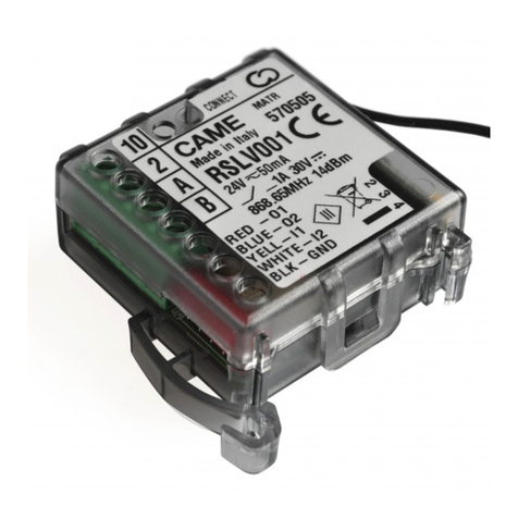
Seav LRX 2035 ALLARM EASY User manual

LRX 2035 ALLARM EASY


3
QUADRO ELETTRONICO LRX 2035 ALARM
Quadro elettronico che integra un controllo per motore
monofase 230Vac e per Centrale di Allarme per la su-
pervisione di 2 zone cablate.
Il quadro elettronico è provvisto di carica batteria in-
tegrato e ricevente radio, è ideale per l’automazione e
messa in sicurezza di garage con portoni, basculanti e
serrande avvolgibili.
Il quadro elettronico può essere usato in modo combi-
nato, in modo che la gestione dell’automazione e del
sistema di allarme sia riferita ad un unico comando, o in
modo separato cioè un controllo per la sola automazio-
ne ed un controllo per il solo sistema di allarme.
- Mod. LRS 2035 Alarm : 433,92 Mhz
- Mod. LRS 2035 SET Alarm : 433,92 Mhz
“narrow band”
- Mod. LRH 2035 Alarm : 868,3 Mhz
“narrow band”
IMPORTANTE PER L’UTENTE
- Il dispositivo può essere utilizzato da bambini di età
superiore a 8 anni o da persone con ridotte capacità
psico-fisiche o con poca conoscenza ed esperienza
solamente se supervisionati o istruiti sul funziona-
mento e le modalità di utilizzo in maniera sicura per
capire anche i pericoli coinvolti nel suo utilizzo.
- Queste istruzioni sono disponibili anche sul sito
www.seav.com
- Non consentire ai bambini di giocare con il dispositivo
e tenere lontano dalla loro portata i radiocomandi.
- Esaminare frequentemente l’impianto per rilevare
eventuali segni di danneggiamento. Non utilizzare il
dispositivo se è necessario un intervento di ripara-
zione.
- Ricordarsi sempre di togliere l’alimentazione prima di
effettuare operazioni di pulizia o manutenzione.
- Le operazioni di pulizia e manutenzione non devono es-
sere eseguite da bambini senza essere supervisionati.
ATTENZIONE: conservare questo manuale d’istruzio-
ni e rispettare le importanti prescrizioni di sicurezza in
esso contenute. Il non rispetto delle prescrizioni potreb-
be provocare danni e gravi incidenti.
IMPORTANTE PER L’INSTALLATORE
1) Prima di automatizzare il serramento è necessario
verificarne il buono stato, in rispetto alla direttiva
macchine e alla conformità EN 12604.
2) Controllare che la locazione in cui è situata l’instal-
lazione consenta il rispetto dei limiti di temperatura
di esercizio indicata per il dispositivo.
3) La sicurezza dell’installazione finale e il rispetto
di tutte le prescrizioni normative ( EN 12453 - EN
12445) è a cura di chi assembla le varie parti per
costruire una chiusura completa.
4) Usare dispositivi di sicurezza in grado di monitorare
lo stato della loro connessione alla centrale elettrica.
5) Si consiglia, terminata l’installazione, di eseguire
tutti i controlli necessari (programmazione opportu-
na della centrale e corretta installazione dei dispo-
sitivi di sicurezza) per assicurarsi di aver eseguito
un’installazione conforme.
6) L’involucro nella parte posteriore è provvisto di op-
portune predisposizioni per fissaggio a muro (predi-
sposizione per fori per fissaggio mediante tasselli o
fori per fissaggio mediante viti). Prevedere e imple-
mentare tutti gli accorgimenti per una installazione
che non alteri il grado IP.
7) La centrale non presenta nessun tipo di dispositivo
di sezionamento della linea elettrica 230 Vac, sarà
quindi cura dell’installatore prevedere nell’impianto
un dispositivo di sezionamento. È necessario instal-
lare un interruttore omnipolare con categoria III di
sovratensione. Esso deve essere posizionato in modo
da essere protetto contro le richiusure accidentali se-
condo quanto previsto al punto 5.2.9 della EN 12453.
8) Per i cavi di alimentazione si raccomanda di utiliz-
zare cavi flessibili sotto guaina isolante in policlo-
roprene di tipo armonizzato (H05RN-F ) con sezione
minima dei conduttori pari a 1mm2.
9) Il motoriduttore usato per muovere il serramento
deve essere conforme a quanto prescritto al punto
5.2.7 della EN 12453.
10) In accordo al 5.4.2 della EN 12453 è consigliabi le
usare motoriduttori dotati di un dispositivo di sbloc-
co elettromeccanico, per consentire in caso di ne-
cessità, di muovere il serramento manualmente.
11) In accordo al 5.4.3. della EN 12453 utilizzare siste-
mi di sblocco elettromeccanico o dispositivi similari
che permettano al serramento di arrestarsi in sicu-
rezza nella sua posizione di finecorsa.
12) Il cablaggio dei vari componenti elettrici esterni alla
centralina deve essere effettuato secondo quanto
prescritto dalla normativa EN 60204-1 e dalle mo-
difiche a questa apportata dal punto 5.2.7 della EN
I

4
12453. I cavi di alimentazione possono avere un dia-
metro massimo di 14 mm. Il fissaggio dei cavi di ali-
mentazione e di collegamento, deve essere garantito
tramite l’assemblaggio di pressacavi fornibili “optio-
nal”. Prestare attenzione a fissare i cavi in modo che
siano ancorati in modo stabile. Fare attenzione inol-
tre, in fase di foratura dell’ involucro esterno per far
passare cavi di alimentazione e di collegamento, e
di assemblaggio dei pressacavi, ad installare il tutto
in modo da mantenere il più possibile inalterate le
caratteristiche di grado IP della scatola.
13) L’eventuale montaggio di una pulsantiera per il co-
mando manuale deve essere fatto posizionando la
pulsantiera in modo che l’utente non venga a tro-
varsi in posizione pericolosa.
14) Il contenitore Plastico è sprovvisto nella parte re-
movibile dello Switch di collegamento Tampere anti
intrusione, si consiglia il montaggio da parte dell’ in-
stallatore per maggior Sicurezza al Sistema Allarme.
15) La funzione di sicurezza garantita dalla centralina
è attiva solo in chiusura; pertanto la protezione in
apertura deve essere assicurata in fase di instal-
lazione con misure (ripari o distanze di sicurezza )
indipendenti dal circuito di controllo.
16) Per un corretto funzionamento della parte radio ri-
cevente, in caso di utilizzo di due o più centrali, si
consiglia l’installazione ad una distanza di almeno
3 metri l’una dall’altra.
CARATTERISTICHE TECNICHE:
-Alimentazione : 230 Vac 50-60Hz 900W (4A) max.
- Uscita lampeggiante : 230 Vac 50-60 Hz
100W Resistive Load max.
50W Inductive Load max.
- Uscita motore : 230 Vac 50-60Hz 750 W max.
- Ingresso Batteria Tampone : 12 Vdc 2,7A/h max.
- Uscita lampada spia : 12 Vdc 2 W max.
- Uscita alimentazione servizi : 12 Vdc 5 W max.
- Sicurezze e comandi in BT : 12 Vdc
- Temperatura d’esercizio : 10 ÷ 55 °C
- Ricevitore radio : vedi modello
- Trasmettitori op. : 12-18 Bit o Rolling Code
- Codici TX max. in memoria : 120 (CODE o CODE ALARM)
- Dimensioni scheda : 140x145 mm.
- Dimensioni contenitore : 240x190x110 mm.
- Grado di protezione : IP 56
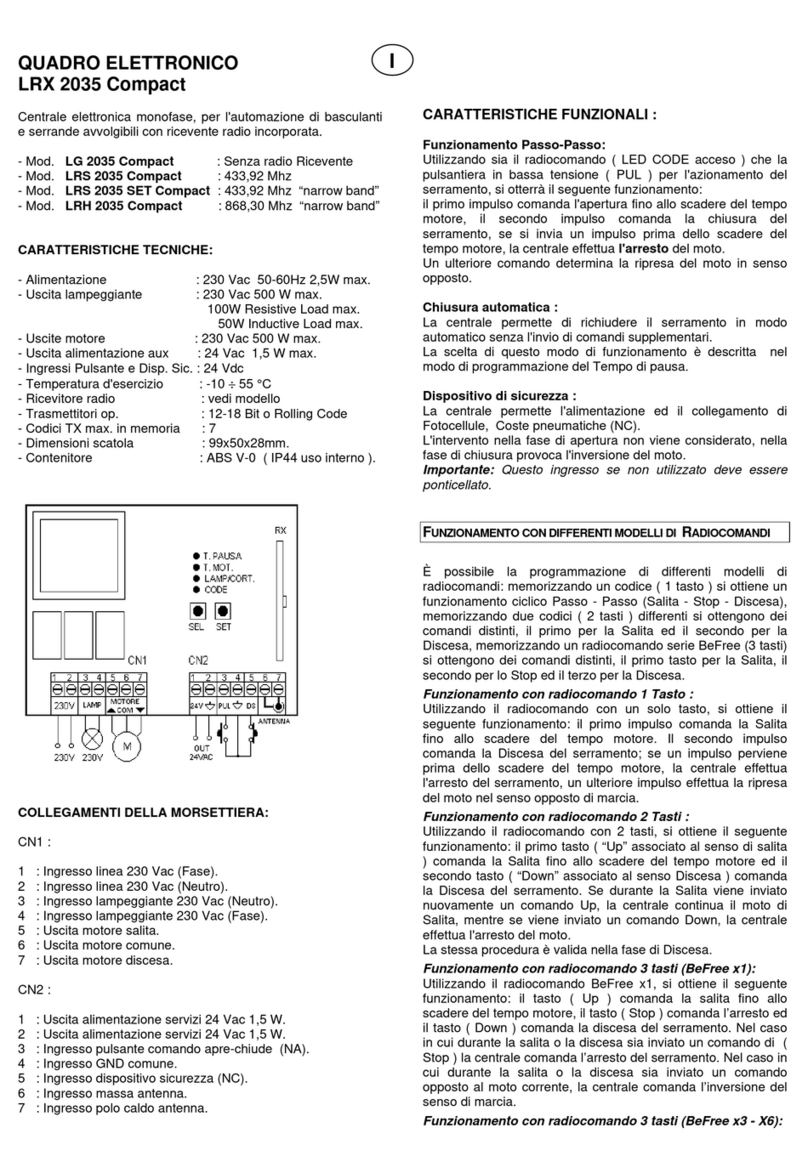
COLLEGAMENTI DELLE MORSETTIERE:
CN1 :
1 : Ingresso linea 230 Vac (Fase).
2 : Ingresso linea 230 Vac (Neutro).
3 : Uscita Lampeggiante 230 Vac (Neutro).
4 : Uscita Lampeggiante 230 Vac (Fase).
5 : Uscita Motore 230V Apertura.
6 : Uscita Motore 230V Comune.
7 : Uscita Motore 230V Chiusura.
CN2:
1 : Alimentazione/Caricabatteria Sirena Allarme + 13,8V.
2 : Uscita Comando Allarme (positivo a mancare).
3 : Alimentazione/Caricabatteria Sirena Allarme GND.
CN3:
1 : Ingresso Positivo Batteria Tampone (+ 12V 2,7Ah max ).
2 :
Ingresso Negativo Batteria Tampone (- 12V 2,7Ah max ).
3 : Uscita Lampada Spia ( + 12V 2W max ).
4 : Uscita Lampada Spia ( - 12V 2W max ).
5 : Uscita Contatto di comando AUX (NC) 30V 1A max.
6 : Uscita Contatto di comando AUX (NC) 30V 1A max.
CN4:
1 : Alimentazione Fotocellule e Sensori Allarme (+ 12V 5W).
2 : Alimentazione Fotocellule e Sensori Allarme (GND).
3 : Ingresso (Z2) Allarme Zona 2 (NC).
4 : Ingresso (Z1) Allarme Zona 1 (NC).
5 : Ingresso GND comune
6 : Ingresso (DS) Dispositivo Sicurezza Motore (NC).
7 : Ingresso (T) Allarme Tampere (NC).
8 : Ingresso GND comune.
9 : Ingresso (P) Pulsante comando Motore (NA).
10 : Ingresso Massa Antenna.
11 : Ingresso Polo caldo Antenna.
CARATTERISTICHE FUNZIONALI:
Utilizzando sia il radiocomando precedentemente me-
morizzato (led CODE acceso) che il pulsante (P) in bassa
tensione per l’azionamento del serramento, si otterrà il
seguente funzionamento:
il primo impulso comanda l’apertura fino allo scadere del
tempo motore o al raggiungimento del fine corsa d’apertu-
ra, il secondo impulso comanda la chiusura del serramen-
to; se si invia un impulso durante la fase di Apertura prima
dello scadere del tempo motore o del raggiungimento del
finecorsa; se si invia un impulso durante la fase di Chiusu-
ra prima dello scadere del tempo motore o del raggiungi-
mento del finecorsa, la centrale effettua l’inversione del
moto. Un ulteriore comando a serramento fermo determi-
na sempre la ripresa del moto in senso opposto.
Chiusura automatica:
La centrale permette di richiudere il serramento in modo
automatico senza l’invio di comandi supplementari. La
La Centrale Elettronica:
LRS 2035 Alarm
LRS 2035 SET Alarm - LRH 2035 Alarm
sono conformi alle specifiche delle Direttive
RED 2014/53/EU, EMC 2014/30/EU, LVD 2014/35/EU.

5
scelta di questo funzionamento è descritta nel modo di
programmazione del Tempo di pausa.
D.S.) Dispositivo di Sicurezza (Fotocellule):
La centrale permette l’alimentazione ed il collegamento di
Fotocellule, Coste pneumatiche (NC).
- Ingresso DS (NC)
L’intervento delle fotocellule nella fase di apertura non
viene considerato, in fase di chiusura provoca l’inversione
del moto.
Chiusura Forzata:
La centrale consente automaticamente nel caso di guasto
o malfunzionamento del Dispositivo di Sicurezza (Ingres-
so DS) di effettuare una Chiusura Forzata volontaria del
Serramento.
Utilizzando sia il radiocomando precedentemente memoriz-
zato (led CODE acceso) che il pulsante in bassa tensione per
sarà possibile effettuare la Chiusura forzata del serramento
nel seguente modo: inviare il comando in modo continuo per
un tempo maggiore a 5 secondi, successivamente il serra-
mento inizierà la fase Chiusura fino al raggiungimento del
finecorsa o dello scadere del tempo motore, a condizione di
aver mantenuto premuto il comando di moto.
A serramento Chiuso la centrale ritorna al normale fun-
zionamento.
Attivazione / Disattivazione Sistema Allarme
(Led CODE ALARM):
La centrale nella configurazione di fabbrica attiva (15
sec. dopo lo scadere del Tempo motore programmato) e
disattiva (immediatamente) automaticamente il Sistema
di Allarme in funzione dello stato di Chiuso o Aperto del
serramento. Utilizzando il radiocomando precedente-
mente memorizzato (led CODE ALARM acceso), si potrà
attivare o disattivare il sistema di allarme a piacimento.
Per ovviare alla possibilità di avere delle false attivazioni
o disattivazioni, il tasto del radiocomando dovrà essere
tenuto premuto in modo continuo per almeno 5 sec. Suc-
cessivamente il Lampeggiante (accensione per 3 secondi)
e soprattutto la Lampada Spia (10 Lampeggi Veloci) indi-
cheranno lo stato selezionato.
Z1 - Z2 ) Dispositivi Allarme (Zona 1 e Zona 2):
La centrale permette l’alimentazione ed il collegamento di
due Sensori di Allarme (NC).
L’intervento dei Sensori di Allarme provocano l’immediata
attivazione dalla Sirena e del contatto OUT AUX (NC).
T) Dispositivo di Sicurezza (Tampere):
La centrale permette il collegamento anti-strappo (Tam-
pere) della Sirena e di tutti i Sensori Allarme (NC). L’in-
tervento provoca l’immediata attivazione dalla Sirena e
del contatto OUT AUX (NC) anche se prima disattivato il
Sistema Allarme tramite il tasto del radiocomando relativo
al CODE ALARM.
Importante: nel caso in cui sia necessario effettuare del-
le manutenzioni, per disattivare il controllo dell’ingresso
Tampere, sarà necessario entrare in modalità Installatore
(vedi paragrafo relativo) prima di ogni intervento nel Siste-
ma Allarme.
Uscita (Sirena Allarme) selezionabile da J1:
La centrale permette il collegamento di Sirene di allarme
standard con alimentazione per il mantenimento della carica
della batteria. L’intervento della Sirena è causato dall’inter-
ruzione della tensione di alimentazione oppure dal comando
dedicato (positivo a mancare default J1 = 1-2 oppure negativo
a mancare J1 = 2-3).
Uscita Allarme Ausiliaria (OUT AUX) selezionabile
da J2:
La centrale dispone di un’uscita OUT AUX (normalmente
chiuso NC default J2 = 2-3 oppure normalmente aperto NA
J2 = 1-2 ) per il collegamento di accessori o altri sistemi di
allarme già presenti. L’attivazione dell’uscita sarà contem-
poranea all’attivazione dell’Allarme fino al disarmo dello
stesso.
Lampada Spia sistema Allarme:
La centrale permette il collegamento di una lampada 12Vdc
2 W max. per la visualizzazione dello stato del Sistema di Al-
larme dell’automazione. Lampada spenta: Allarme disinserito,
accesa Allarme inserito, 10 lampeggi veloci per segnalare At-
tivazioni e Disattivazioni e lampeggiante veloce Allarme persi-
stente in mancanza della rete elettrica o scattato allarme (an-
che se selezionata la modalità di segnalazione temporizzata).
Batteria Tampone 12V 2,7 Ah max:
La centrale permette il collegamento di batteria Tampone, per
garantire il funzionamento della sola parte Sistema Allarme
anche in caso di mancanza della rete elettrica. Dispone inoltre
di un caricabatteria incorporato a 13,8V (sia per il manteni-
mento della batteria Tampone che per quella presente nella
Sirena di Allarme).
PROGRAMMAZIONE:
Tasto SEL: seleziona il tipo di funzione da memorizzare, la
selezione è indicata dal lampeggio del Led. Premendo più
volte il tasto, è possibile posizionarsi sulla funzione deside-
rata. La selezione resta attiva per 10 secondi, visualizzata
dal Led lampeggiante, se trascorsi, la centrale ritorna allo
stato originario.
Tasto SET: effettua la programmazione dell’informazione
secondo il tipo di funzione prescelta con il tasto SEL.
IMPORTANTE: La funzione del tasto SET può anche es-

6
sere sostituita dal radiocomando se precedentemente pro-
grammato (led CODE acceso).
MENU’ PRINCIPALE
La centrale è fornita dal costruttore con la possibilità di
selezionare alcune funzioni importanti.
____________ MENU’ PRINCIPALE ____________
Riferimento Led Led spento Led Acceso
1) CODE Nessun codice Codice inserito
2) CODE ALARM Nessun codice Codice inserito
3) LAMP./CORT. Lampeggiante Luce di Cortesia
4) T. MOT. Tempo motore 30 sec. Tempo programmato
5) T. PAUSA. Senza chiusura aut. Con chiusura aut.
1) CODE: (Programmazione del radiocomando)
Programmazione del radiocomando per il Serramento.
La programmazione dei codici di trasmissione del radioco-
mando associato al funzionamento del Serramento è ese-
guita nel seguente modo: premere il tasto SEL, il LED CODE
inizierà a lampeggiare, allo stesso tempo inviare il codice di
trasmissione con il tasto del radiocomando associato; a que-
sto punto il LED CODE rimarrà acceso e la programmazione
sarà completata.
Regola del primo Radiocomando memorizzato:
Nella programmazione dei radiocomandi vige la seguente
regola: se il primo radiocomando ad essere memorizzato
è un radiocomando di tipo Rolling Code la centrale accet-
terà poi solo radiocomandi Rolling Code, garantendo così
una maggiore sicurezza antintrusione; se invece il primo
radiocomando ad essere memorizzato è un radiocomando
a codice fisso il ricevitore accetterà poi sia radiocomandi a
codice fisso che radiocomandi Rolling Code.
Radiocomando già presente in memoria o non com-
patibile:
La centrale permette di memorizzare fino a 120 radioco-
mandi aventi codice diverso fra loro. Nel caso cui si provi
ad eseguire la procedura di programmazione di un dispo-
sitivo già presente in memoria o non compatibile, il LED
CODE inizierà a lampeggiare velocemente per qualche
istante segnalando l’impossibilità, per poi tornare di nuovo
alla fase di programmazione.
Numero massimo dispositivi memorizzabili:
La centrale permette di memorizzare fino a 120 radioco-
mandi aventi codice diverso fra loro. Nel caso in cui il
numero massimo dispositivi memorizzabili sia stato rag-
giunto, ripetendo l’operazione di programmazione, la cen-
trale evidenzia il fallimento dell’operazione effettuando il
lampeggio di tutti i led ad eccezione del LED CODE che
resta acceso fisso. Dopo 10 secondi la centrale esce dalla
programmazione.
2) CODE ALARM: (Programmazione del radiocoman-
do x Attivazione disattivazione sistema di Allarme).
La procedura di programmazione e cancellazione è analoga
a quella descritta precedentemente ma ovviamente riferita
al Led CODE ALARM, con la sola differenza che la program-
mazione è riferita ad un tasto dedicato al Radiocomando per
l’attivazione e la disattivazione del Sistema Allarme.
Importante: nel caso in cui non sia stato programmato
nessun Codice Allarme (CODE ALARM OFF) la centrale non
controlla i collegamenti e le funzionalità relative al Siste-
ma Allarme.
3) LAMP/CORT: (Selezione lampeggiatore, luce di
cortesia).
La centrale dispone di una uscita 230Vac, per il collegamento
di un lampeggiante o di una luce di cortesia. La centrale è
fornita dal costruttore con la funzione. Lampeggiatore anche
in pausa abilitata. Se si desidera abilitare il funzionamento
Lampeggiatore, procedere nel seguente modo: posizionarsi
con il tasto SEL sul lampeggio del LED LAMP/CORT poi pre-
mere il tasto SET, il LED LAMP/CORT si accenderà perma-
nentemente. Ripetere l’operazione se si desidera ripristinare
la configurazione di fabbrica. Se si desidera abilitare la luce
di cortesia, ripetere l’operazione sopra descritta, premendo il
tasto SEL due volte (ottenendo il lampeggio veloce del LED
LAMP/CORT) anziché una volta. Ripetere l’operazione se si
desidera ripristinare la configurazione di fabbrica.
Funzionamento Lampeggiatore anche in pausa: L’uscita
230Vac si attiverà ogni volta che l’automazione è in movi-
mento, per la durata del tempo motore. Nel caso in cui sia
memorizzato il Tempo di Pausa, l’uscita 230Vac sarà attiva
anche durante la Pausa.
Funzionamento Lampeggiatore: L’uscita 230Vac si atti-
verà ogni volta che l’automazione è in movimento, per la
durata del tempo motore.
Funzionamento Luce di Cortesia: L’uscita 230Vac si
attiverà per la durata di 3 minuti, ogni qualvolta sarà im-
partito un comando di apertura.
Importante: Il Lampeggiatore / Luce di Cortesia, si attive-
rà anche in contemporanea con l’attivazione del Sistema
di Allarme, fino al disarmo dello stesso.
4) T. MOT: (Programmazione tempo di lavoro 4 minuti
max.)
La centrale è fornita dal costruttore con un tempo di lavoro
motore predefinito pari a 30 sec. Se occorre una riprogram-
mazione del tempo di lavoro motore, deve essere effettuata
a serramento chiuso nel seguente modo: posizionarsi con
il tasto SEL sul lampeggio del LED T. MOT. poi premere in

7
modo continuo il tasto SET, il serramento inizieràla fase di
salita, al raggiungimento del punto desiderato lasciare il
tasto SET, nello stesso momento si determinerà la memoriz-
zazione del tempo motore e il LED T. MOT. sarà acceso fisso.
5) T. PAUSA: (Programmazione tempo chiusura aut.
4 min. max.)
La centrale è fornita dal costruttore con chiusura auto-
matica (tempo di pausa pari a 15 sec.). Se occorre una
riprogrammazione del tempo di chiusura automatica,
deve essere effettuata a serramento chiuso nel seguente
modo: posizionarsi con il tasto SEL sul lampeggio del LED
T. PAUSA poi premere in modo continuo il tasto SET per un
tempo uguale a quello desiderato di pausa tra la fine della
fase di apertura e la chiusura del serramento, allo scadere
del tempo desiderato lasciare il pulsante SET, nello stesso
momento si determinerà la memorizzazione del tempo di
chiusura automatica e il LED T. PAUSA. sarà acceso fisso.
Se si desidera non avere la chiusura automatica, posizio-
narsi sul lampeggio del LED T. PAUSA poi premere per
meno di 1 secondo il tasto SET , nello stesso tempo il LED
si spegnerà e l’operazione sarà conclusa.
ULTERIORI OPZIONI PROGRAMMABILI:
- Selezione funzionamento Uscita OUT AUX.
- Programmazione Radiocomando Allarme per Attivazio-
ne/Disattivazione Parziale con esclusione Zona 1.
- Funzionamento Ingresso P = Ingresso AUX.
- Selezione funzionamento info Lampada Spia.
______________ MENU’ ESTESO 1 _____________
Riferimento Led Led spento Led Acceso
A) CODE
OUT AUX = Monostatile OUT AUX = Bistatile o Temp.
B) CODE ALARM Code Alarm Parz = OFF Code Alarm Parz = ON
C) LAMP./CORT. P = Ingresso Pulsante P = Ingresso AUX
D) T. MOT. L.SPIA = Info ON. L.SPIA = Info Temp.
E) T. PAUSA. Menù 1 = Lampeggio 1110-1110-1110 ......
..
- Ingresso P e T = Finecorsa CH e AP.
- Ingresso P e T = Pulsanti DOWN e UP.
- Funzionamento Uomo Presente in Chiusura.
_____________ MENU’ ESTESO 2 _____________
Riferimento Led Led spento Led Acceso
A) CODE P e T = default P = FC. CH e T = FC. AP
B) CODE ALARM P e T = default P = UP e T = DOWN
C) LAMP./CORT. Uomo presente CH=OFF Uomo presente CH=ON
D) T. MOT. Non usato Non usato
E) T. PAUSA. Menù 2 = Lampeggio 1110-1110-1110 ........
- Per approfondimenti alle funzioni sopra elencate
consultare il sito www.seav.com
RESET:
Nel caso sia opportuno ripristinare la centrale alla configu-
razione di fabbrica, premere il tasto SEL e SET in contem-
poranea, allo stesso tempo si otterrà l’accensione contem-
poranea di tutti i led ROSSI di segnalazione e subito dopo
lo spegnimento.
ATTIVAZIONE MODALITÀ INSTALLATORE:
Nel caso ci sia l’esigenza di effettuare manutenzioni nel
sistema Allarme, è necessario Attivare la modalità Instal-
latore per far si che venga disattivato il Sistema di Allar-
me ed il controllo dell’ingresso Tampere, se si desidera
la Modalità Installatore, procedere nel seguente modo:
sconnettere e riconnettere l’alimentazione di rete 230Vac
alla centrale, tenendo premuto in modo continuo per 10
sec. il tasto del Radiocomando relativo al CODE ALARM
precedentemente memorizzato, allo stesso tempo si ot-
terrà un breve lampeggio di tutti i Led di segnalazione e
simultanea attivazione dell’uscita Lampeggiante per 3 sec,
quindi la programmazione sarà completata. La modalità In-
stallatore viene automaticamente disattivata a primo ciclo
di normale funzionamento del serramento o all’attivazione
del Sistema di Allarme.
DIAGNOSTICA:
Test input comandi e Sensori:
In corrispondenza ad ogni ingresso di comando o sensore
in bassa tensione, la centrale dispone di un LED di segna-
lazione, in modo tale da poter controllare rapidamente lo
stato.
Logica di funzionamento: LED acceso ingresso chiuso, LED
spento ingresso aperto.
GESTIONE LED DI PROGRAMMAZIONE:
La centrale dopo 3 minuti di inattività nella procedura di
programmazione, effettua lo spegnimento automatico dei
LED di programmazione per risparmio energetico. La sola
pressione dei tasti SEL, SET o il ricevimento di un coman-
do di moto, attiverà l’accensione dei LED in base alle pro-
grammazioni impostate precedentemente.
Rev. 3.0 13/06/2016

8
ELECTRONIC PANEL LRX 2035 ALARM
Control panel that integrates electronic control for
single-phase motor 230 Vac and Alarm System for the
supervision of 2 wired zones.
The control panel, equipped with intergrated battery
charger and radio receiver, is ideal for automation and
safety of garage doors, over head doors and rolling
shutters.
The control panel can be used in a combine manner, so
that the management of automation and alarm system
is reported to a single command, or so that a separate
control for automation alone and a control for the alarm
system alone.
- Mod. LRS 2035 Alarm : 433,92 Mhz
- Mod. LRS 2035 SET Alarm : 433,92 Mhz
“narrow band”
- Mod. LRH 2035 Alarm : 868,3 Mhz
“narrow band”
IMPORTANT FOR THE USER
- The device can be used by up to 8-year-old children or
persons with reduced physical-psychological abilities
or with little knowledge and experience, only if they
are supervised or trained on the functioning and the
use modalities in a safe way, to better know also the
dangers during its use.
- This instructions are available also on the website
www.seav.com.
- Do not allow children to play with the device and keep
the radio-controls away from their reach.
- Frequently examine the plant to detect any signs of
damaging. Do not use the device if a repair interven-
tion is necessary.
- Always remember toremove the power source before
polish or maintenace works.
- Polish and maintenance works must not be done by
children without any supervision.
ATTENTION: keep this instruction manual and respect
the important safety prescriptions contained herein.
The not compliance with the prescriptions may cause
damages and serious accidents.
IMPORTANT FOR THE INSTALLER
1) Before automating the frame, check that it is in
good conditions, in compliance with the Machinery
Directive and with EN 12604.
2) Control that place, where the installation is situat-
ed, respects the Temperature working limits, fixed
for the device.
3) The safety for the final installation and the respect
of all the rules (EN 12453 – EN 12445) are under
responsability of the person, who Assembly all the
parts together for building a closing.
4) Use safety disposals which can control their connec-
tion to the Electric panel.
5) To be sure of having done a right installation, you
should do a coplete check-up (progra-mation of the
electric unit and correct installation of safety dis-
posals).
6) In the back side, the shell is equipped with wall
fastening set up (holes for fastening by dowels or
screws). Consider and implement all Efforts for an
installation that does not change the IP degree.
7) The control unit does not have any type of isolating
device for the 230 Vac line. It will therefore be the
responsibility of the installer to Arrange an isolating
device inside the plant. It is necessary to install A
monophase switch with over-voltage category III.
It must be Positioned where it can protected from
accidental closing, according To that prescribed in
point 5.2.9. of EN 12453.
8) For what concerning cables for power, you should
use flexible Cables under policloroprene insulating
sheath of harmonized type (H05RN-F) with 1mm²
minimum size of conductor wires.
9) The gearmotor used to move the frame must comply
with that prescribed at point 5.2.7 of EN 12453.
10) In compliance with 5.4.2 of EN 12453, it is recom-
mended to use gearmotors equipped with an elec-
tric-mechanical release device, so that the door can
be moved manually in case of necessity.
11) In compliance with 5.4.3 of EN 12453, use electric-
mechanical release systems or similar devices
which stop the door safely in the end run position.
12) Wiring of the various electrical components outside
of the control unit must be carried out in compliance
with that prescribed in Standard EN 60204-1 and its
amendments at point 5.2.7 of EN 12453. Cables for
power can have a 14 mm Maximum diameter size.
Power supply and connection cables must be fixed
using the cable “optional” provided. Please Be
GB

9
aware of fixing the cables in order to attach
them in a solid Way. Moreover, during the shell
drilling phase to let the power and connection
cables go through, and the cable glands assem-
bly, warning to Install everything in order to
maintain unchanged the IP-degree properties of
the box.
13) Mounting of a push button panel for manual
control must be done positioning the push but-
ton panel where the user is not in a dangerous
position.
14) The plastic box is lacking in anti-intrusion Tampere
connection In the removable part of the Switch, so
it is recommended the Assembly by the installer for
a major safety to the Alarm system.
15) The safety function, guaranteed by the electronic
unit, operates Only during the closure; so the open-
ing protection must be Guaranteed by independent
actions (havens or safety distance) From the control
circuit during the installation.
16) For a correct functioning of the radio receiver, if us-
ing one or More control units, the installation at a
minimum distance of at least 3 metres one from the
other is recommended.
TECHNICAL DATA:
-Power supply : 230 Vac 50-60Hz 900W (4A) max.
- Flashing light output : 230 Vac 50-60 Hz
100W Resistive Load max.
50W Inductive Load max.
- Motor output : 230 Vac 50-60Hz 750 W max.
- Buffer battery input : 12 Vdc 2,7A/h max.
- Alarm light output : 12 Vdc 2 W max.
- Power supply service output : 12 Vdc 5 W max.
- Safety and BTcontrols : 12 Vdc
- Working temperature : 10 ÷ 55 °C
- Radio receiver : see model
- Op. transmitters : 12-18 Bit or Rolling Code
- Max. TX codes in memory : 120 (CODE or CODE ALARM)
- Board dimensions : 140x145 mm.
- Box dimensions : 240x190x110 mm.
- Protection degree : IP 56
CONNECTIONS OF TERMINAL BOARDS:
CN1 :
1 : 230 Vac input (phase).
2 : 230 Vac input (Neutral).
3 : 230 Vac flash input (Neutral).
4 : 230 Vac flash input (phase).
5 : Opening 230V motor output.
6 : Common 230V motor output.
7 : Closing 230V motor output.
CN2:
1 : Power supply/ Battery charger Alarm signal + 13,8V.
2 : Alarm Control Output (positiv to miss).
3 : Power supply/ Battery charger Alarm signal GND.
CN3:
1 : Positive buffer battery input (+ 12V 2,7Ah max).
2 :
Negative buffer battery input (- 12V 2,7Ah max).
3 : Signal light output (+ 12V 2W max).
4 : Signal light output (- 12V 2W max).
5 : AUX control contact output (NC) 30V 1A max.
6 : AUX control contact output (NC) 30V 1A max.
CN4:
1 : Power supply Photocells and Alarm sensors (+ 12V 5W).
2 : Power supply Photocells and Alarm sensors (GND).
3 : Input (Z2) Alarm zone 2 (NC).
4 : Input (Z1) Alarm zone 1 (NC).
5 : Common GND input.
6 : Input (DS) Safety motor Device (NC).
7 : Input (T) Tamper Alarm (NC).
8 : Common GND input.
9 : Input (P) Motor control Button (NA)
10 : Ground Antenna input.
11 : Hot pole Antenna input.
OPERATING FEATURES:
Using both the memorized radio-control (led CODE on) and
the Button (P) with low tension for the operation of doors
and windows, You will get the following operation:
The firs input rules the opening till the end of motor time or
till the Achievement of opening final run; the second input
rules the closure. If you send an input during the opening,
before the end of motor time Or the final run achievement,
or if you send an input during the Closing, before the end
of motor time or the final run achievement, The electronic
unit will do the reversal operation. Another input with sta-
tionary doors or windows always represents A restart of
the reversal operation.
Automatic closing:
The control unit closes the frame automatically without
sending other Commands. The choice of this operating
mode is described under The instruction for setting the
delay period.
Electronic control unit:
LRS 2035 Alarm
LRS 2035 SET Alarm - LRH 2035 Alarm
Comply with the specifications of the Directives
RED 2014/53/EU, EMC 2014/30/EU, LVD 2014/35/EU.

10
D.S.) Safety device (Photocells):
The control unit allows the connection and the control of
Photocells, Tyre sensors (NC).
- Input DS (NC)
During opening the operation of photocells is not contem-
plated, During closing it causes the reversal movement.
Forced Closing:
In case of damage or malfunction of the Safety Device
(Input DS), the electronic panel automatically does a vol-
untary forced closing of The frame.
Using both the memorized radio control (led CODE on) and
the low tension button, you can do the forced closing In the
following way: to keep sending the command for a higher
time Of 5 seconds, then the frame starts the closing till
the run-end or till The end of motor time, but only having
pushing the move command.
With closed frame, the electronic panel turns to the nor-
mal function.
Activation/Deactivation Alarm System
(Led CODE ALARM):
By manufacturing arragement, the electronic panel starts
(15 Seconds after the end of the programmed motor time)
and Automatically cuts (immediately) the Alarm system of
the close or Open frame. Using the memorized radio con-
trol (led CODE ALARM on), you can start or cut the Alarm
system as you want. Avoiding false activations or deacti-
vations, the button of the radio Control has to be pushed
for at least 5 seconds. Then the flashing Light (on for 3
seconds) and the Alarm light (10 rapid flashes) will Show
the choosen movement.
Z1 - Z2 ) Alarm Devices (zone 1 and zone 2):
It is possible to connect and supply 2 Alarm sensors (NC).
They can immediately activate the siren and the OUT AUX
Contact (NC).
T) Safety Device (Tampere):
It is possible to do the anti-split connection (Tampere) of
the siren and all the other alarm sensors (NC).
This can do the activation of the siren and the OUT AUX
contact (NC), even if the alarm system was cut by the
CODE ALARM Command.
Important: in case of maintenance, in order to cut the
control of The Tampere input, it will be necessary to swich
to Installer Mode (see the connected paragraph) before
every operation On the Alarm system.
Output (Sirens) from J1:
It is possible to connect standard sirens with supply for bat-
tery charge upkeeping. With siren on, the battery supply is
stopped .
Or this can be caused by the related command (positive to
miss Default J1=1-2 or negative to miss J1=2-3).
Auxiliary Alarm Output (OUT AUX) from J2:
The electronic panel has an OUT AUX output (normally close
NC default J2=2-3 or normally open NA J2=1-2) for the
Connection of accessories or other present alarm systems.
The activation of the output will be simultaneous to the ac-
tivation Of the alarm till its switching off.
Light Alarm System:
It is possible to connect a light 12Vdc 2W max. to know the
alarm Status of the automation. Light off: alarm off; light on:
10 rapid Flashes for activations and disactivations and rapid
light with Lasting alarm for no electrical line, wireless sensor
out of Batteries or alarm on (also with time-signal mode).
Buffer Battery 12V 2,7Ah max:
It is possible to connect a buffer battery to make in work only
the Alarm system, also with electrical line missing. Moreover
it has An incorporated battery charger 13,8V (both for buffer
battery And the one in the alarm siren).
PROGRAMMING:
SEL button: selects the type of function to be memorised.
The selection is indicated by a flashing LED.
By repeatedly pressing the button it is possible to choose
the Desired function. The selection will remain active for 10
seconds indicated by a flashing LED. If no other operations
are executed during this period, the control board will return
to its previous state.
SET button: programs the information relative the type of
function previously selected with the SEL button.
IMPORTANTE the function of the SET button can also be
replaced With radio control if it was programmed before
(led CODE on).
MAIN MENU’
The electronic panel is supplied with the possibility to se-
lect some important functions.
________________ MAIN MENU’ ________________
LED Reference LED Off LED On
1) CODE No code Device activated
2) CODE ALARM No code Device activated
3) LAMP./CORT. Flashing Lamp Courtesy Light
4) T. MOT. Programmed 30’’ Programmed delay
5) T. PAUSA. No automatic close With automatic close
1) CODE: (Programming of radio controls)
Programming of radio control for frame:
The programming of transmission codes of radio control for
the Frame operation is done in the following way: push SEL

11
button, LED CODE starts lighting, in the meanwhile send
the transmission Code with the related radio control, at this
point the LED CODE will Stay on the programming will be
completed.
Rule of the first memorized radio control:
In radio controls programming there is the following rule: if
the first Memorized radio control is a Rolling Code one, the
electronic panel will accept only Rolling Code radio con-
trols, with more anti-Intrusion safety; if instead the first
memorized radio control has fixed Code, the receiver will
accept both fixed codes and Rolling Code Radio controls.
Radio control already in memory or incompatible:
It is possible to memorize up to 120 radio controls with
different Codes. In case of programming devices already
in memory or Incompatible, the LED CODE starts flashing
rapidly for some instant, Flaging the impossibility and then
it will return to programming.
Highest number of memorized devices:
It is possible to memorize up to 120 radio controls with dif-
ferent Codes. In case of the hightest number of memorized
devices is Reached, repeating the programming, the elec-
tronic panel flags the Error by the flashing of all the leds save
the LED CODE, which stays Fixed on. After 10 seconds the
electronic panel exits from the Programming mode.
2) CODE ALARM: Programming of the radio control
for the Activation/deactivation of the alarm system).
The method of programming and cancellation is similar
to the one Described before, but related to LED CODE
ALARM, with the only Difference that it is refered to a
button, related to the radio control for Activation and de-
activation of the alarm system.
Important: when any Alarm Code was not programmed
(CODE ALARM OFF), the panel does not control connec-
tions and functions Of the Alarm System.
3) LAMP/CORT: (Selection of the flashing light or the
courtesy light).
The control unit has a 230 Vac output, for connection to a
flashing light or a courtesy light. The control unit is sup-
plied by the manufacturer with the flashing function even
with delay enabled. If you wish to set up the flashing
light function, proceed as follows: use the SEL button to
navigate to the LAMP/CORT LED when flashing and then
press the SET button. The LAMP/CORT button will light
up permanently.
Repeat the operation if you wish to put the previous configu-
ration Back into operation. If you wish to set up the courtesy
light, repeat The operation described above, pressing the
SEL button twice instead of once (the LAMP/CORT LED will
flash rapidly). Repeat the operation if you wish to put the
previous configuration back into Operation.
Flashing Light function even in pause: the 230 Vac out-
put will be Activated each time that the automation is mov-
ing, for the duration of the motor time. If the pause time is
memorised, the 230Vac output will be active even during the
delay.
Flashing function: The 230 Vac output will be activated
each time that the automation is moving, for the duration
of the motor time.
Functioning of the Courtesy light: he 230 Vac output
will be activated for 3 minutes, each time that an opening
command is Given.
Important:the flashing/Courtesy light will be acti-
vated at the Same time with the Alarm System, till its
switching off.
4) T. MOT: (Programming the motor operating time
max. 4 Minutes).
The control unit is factory supplied with a predefined
working time motor equal to 30 sec. If a reprogramming
of the motor operating time is needed, it must be carried
out through the closed frame in the following manner:
use the SEL button to navigate to the T. MOT LED when
flashing, then continuously press the SET button. The
rolling shutter will start the opening.
When you have reached the required height, release the
SET button and at the same time the motor time storage
will be completed and the T. MOT. LED will remain lit
and fixed.
5) T. PAUSE: (Maximum programmed automatic clos-
ing 4 minutes.)
The manufacturer furnishes the control unit with an
automatic closure (pause time equal to 15 sec.). If a re-
programming of the automatic closing time is needed,
it must be carried out through the closed frame in the
following manner: use the SEL button to navigate to the
T. PAUSE LED when flashing. Then press and hold down
the SET button for a period equal to the Desired pause
interval between closing and opening operations. At
expiration of the desired time release the SET button.
At the same time the memorisation of automatic clos-
ing time will be determined and the T. PAUSE LED will
remain lit.
If you do not want automatic closing, take position on
the T. PAUSE LED when flashing. Then press the SET
button for lessthan a second. At the same time the LED
will shut off and the operation will be concluded.

12
OTHER OPTIONS:
- Selecting OUT AUX exict function.
- Programmig Radiococotrol Alarm for partial Activation /
Deactivation with exclusion of Zone 1.
- Functioning P input = AUX input.
- Selecting functioning info Flash Light.
_____________ EXTENDED MENU’ 1 _____________
LED Reference LED Off LED On
A) CODE
OUT AUX = Monostable
OUT AUX = Double-Stable or Temp.
B) CODE ALARM Code Alarm Part = OFF Code Alarm Part = ON
C) LAMP./CORT. P = Command Input P = AUX Input
D) T. MOT. Lamp Light = Info ON Lamp Light = Info Temp.
E) T. PAUSE. Menù 1 = Mode Flashing 1110-1110-1110 ......
..
- P and T input= End-course CH e AP.
- P and T input= DOWN e UP buttons.
- Functioning dead man in Closing.
_____________ EXTENDED MENU’ 2 _____________
LED Reference LED Off LED On
A) CODE P e T = default P = FC. CH e T = FC. AP
B) CODE ALARM P e T = default P = UP e T = DOWN
C) LAMP./CORT. User present CH=OFF User present CH=ON
D) T. MOT. Not Used Not Used
E) T. PAUSA. Menù 2 = Mode Flashing 1110-1110-1110 ........
- For futher information to the functioncs above visit
the web site www.seav.com
RESET:
To reset the default configuration of the control unit, press
the SEL and SET buttons simultaneously; all RED indicator
LEDs will switch on and then off again immediately.
INSTALLER ACTIVATION MODE:
In case of maintenance of the alarm system, it is neces-
sary to Activate the installer mode in order to deactive de
alarm system And the Tampere control input, if you wish
this mode, proceed as Follows: disconnect and reconnect
the 230 Vac supply line to the Unit, keeping pushing for at
least 10 seconds the memorized CODE ALARM Button of
the radio control, at the same time You get a short flash
of all the leds and the simultaneous Activation of Lamp
light output for 3 seconds, so the programming Is done.
Automatically the installer mode is deactivated at the First
cycle of normal functioning of frame or at the activation of
the Alarm system.
DIAGNOSTICS :
Command Input Test and Sensors:
In correspondence to each low voltage input command,
the control unit uses LED signals allowing rapid status
control.
Functioning logic: a lit LED means input closed, an unlit
LED means input open.
MANAGEMENT OF PROGRAMMING LEDS:
After 3 minutes of inactivity during the programming, the
unit Automatically turns off the programming leds for sav-
ing energy. With a pressure of SEL or SET buttons, or a
moving delivery Command, the LEDs will turn on, basing
on memorized Programming.
Rev. 3.0 13/06/2016

13
TABLEAU ELECTRONIQUE LRX 2035 ALARM
Tableau électronique qui accomplit une commande
pour le moteur monophasé 230Vac et pour la centrale
d’Alarme, pour la surveillance de 2 zones câblées. Le
tableau électronique, fourni de batterie chargeur inté-
gré et récepteur radio, est idéal pour l’automatisation
et mise en sécurité des garages avec bâtiments, bas-
culants et volets roulants. Le tableau électronique peut
être utilisé de façon combinée, donc la gestion de l’au-
tomatisation et du système d’alarme soit reliée à une
seule commande, ou de façon séparée, c’est-à-dire une
commande pour l’automatisation et une commande
pour le système d’alarme.
- Mod. LRS 2035 Alarm : 433,92 Mhz
- Mod. LRS 2035 SET Alarm : 433,92 Mhz
“narrow band”
- Mod. LRH 2035 Alarm : 868,3 Mhz
“narrow band”
INFORMATIONS IMPORTANTES POUR L’UTILISATEUR
- Le dispositif peut être utilisé par des enfants qui ont
un âge superieur à 8 ans ou par des personnes aux
capacités psychophysiques réduites ou avec peu de
connaissance et d’experience seulement s’ils sont
contrôlés ou instruits sur le fonctionnement et l’uti-
lisation de façon sûre, pour apprendre les dangers
pendant son utilisation.
- Cettes consignes sont disponibles aussi sur le site
www.seav.com.
- Ne pas autoriser les enfants à jouer avec le dispositif
et garder les radiocommandes hors de leur portée.
- Examiner fréquemment l’installation pour relever
d’éventuels signes d’endommagement. Ne pas uti-
liser le dispositif s’il nécessite une intervention de
réparation.
- Se souvenir de toujours enlever la source d’énergie
avant les operations de nettoyage ou de maintenance.
- Les operations de nettoyage et de maintenance ne
doivent pas être faites par des enfants sans sourveil-
lance.
ATTENTION: conserver ce livret d’instructions et res-
pecter les importantes prescriptions de sécurité qui y
figurent.
Le non respect des prescriptions pourrait provoquer des
dommages et de graves accidents.
INFORMATIONS IMPORTANTE POUR
L’INSTALLATEUR
1) Avant de procéder à l’automatisation du volet il faut
en vérifier le bon état, conformément à la directive
machines et à la EN 12604.
2) Controller que la location où se trouve l’installation
respect les limites de température d’excercise, indi-
quée sur le dispositif..
3) La sécurité de l’installation finale et le respect de
toutes les lois normatives (EN 12453 – EN 12445)
sont assurés par la personne qui monte les diffé-
rentes parties pour construire une fermoir complet.
4) Utiliser des dispositifs de sécurité qui peuvent sur-
veiller leur raccord à la centrale électrique.
5) À installation terminée, on conseiile de faire tous
les controles nécessaires (correcte programmation
de la centrale et correcte installation des dispositifs
de sécurité) pour avoir une installation conforme.
6 La coque, dans la partie derrière, est fournie avec des
dispositions, justes pour la fixation à mur (par trous
pour la fixation à travers des goupilles ou des vis).
Prendre toutes les précautions pour une installation
qui ne change pas le degré IP.
7) La centrale n’a pas aucun type de dispositif de-
sectionnement de la ligne électronique 230 Vac,
doncl’installateur devra prévoir un dispositif de
sectionnement dansl’équipement. Il faut installer
un interrupteur monophasé aveccatégorie III de
surtension. Il doit être installé de façon d’êtreproté-
gé contre les fermetures accidentaux selon le point
5,2,9 de la loi EN 12453.
8) Pour l’alimentation, on coseille d’utiliser câble
flexible sousgaine isolante en policloroprene de
type harmonisé (H05RN-F) avec section minimale
1mm² des fils conducteurs.
9) Le motoréducteur utilisé pour déplacer le volet doit
êtreconforme aux indications mentionnées au point
5.2.7 de la EN12453.
10) Conformément au point 5.4.2 de la EN 12453 nous-
conseillons d’utiliser des motoréducteurs dotés
d’un dispositifde déblocage électromécanique, de
façon à faciliter, sinécessaire, le déplacement ma-
nuel de la porte.
11) Conformément au point 5.4.3. de la EN 12453 uti-
liser dessystèmes de déblocage électromécanique
ou des dispositifsidentiques qui permettent à la
porte de se bloquer, en toutesécurité, en position
de fin de course.
12) Le câblage des différents composants électriques
externesà la centrale doit être effectué confor-
mément à la norme EN60204-1 et aux modifi-
F

14
cations apportés à cette dernière au point 5.2.7
de l EN 12453. Les câbles d’alimentation peuvent
avoirun diamètre maximal de 14 mm.La fixation des
câblesd’alimentation et de , doit être garantie par
l’assemblage desserre-câbles fournis «optional».
Fixer les câbles de façon qu’ilssoient attachés de
manière stable. En outre, pendant le percement de la
coque extérieure pour lescâbles d’alimentation et de
branchement et l’assemblage despresscâbles, faire
attention à installer tous de façon de nechanger pas
les caractéristiques de degré IP de la boîte.
13) L’éventuel montage d’un clavier pour la comman-
demanuelle doit être effectué en positionnant le
clavier de façon àce que l’utilisateur ne se trouve
dans une position dangereuse.
14) La boîte en plastique est fournie avec le Switch de-
branchement Tampere anti-intrusion, dans la partie
mobile. Oncoseille le montage par l’installateur pour
une majeure securitéau système d’alame.
15) La fonction de securité garantie par le tableau est
activeseulement en clôture; donc la protection en
ouverture doit êtreassurée pendant l’installation
avec mesures (arbris oudistances de sécurité) indé-
pendants du circuit de contrôle.
16) Pour que la partie radio réceptrice fonctionne
correctement,en cas de deux ou de plusieurs cen-
trales utilisées, nousconseillons de les installer à 3
mètres de distance minimuml’une de l’autre.
CARACTÉRISTIQUES TECHNIQUES:
-Alimentation: : 230 Vac 50-60Hz 900W (4A) max.
- Sortie clignotante: : 230 Vac 50-60 Hz
100W Resistive Load max.
50W Inductive Load max.
- Sortie moteur : 230 Vac 50-60Hz 750 W max.
- Entrées batterie Tampone : 12 Vdc 2,7A/h max.
- Sortie lampe lumière : 12 Vdc 2 W max.
- Sortie alimentation services : 12 Vdc 5 W max.
- Sécurité et commandes en BT: 12 Vdc
- Température d’exercice : 10 ÷ 55 °C
- Récepteur radio : voir modèle
- Transmetteurs op. : 12-18 Bit ou Rolling Code
- Codes TX max. en mémoire : 120 (CODE ou CODE ALARM)
- Dimensions carte : 140x145 mm.
- Dimensions boîtier : 240x190x110 mm.
- Degré de protection : IP 56
BRANCHEMENTS DE LA BARRETTE DE RACCORDEMENT:
CN1 :
1 : Entrée ligne 230 Vac (Phase).
2 : Entrée ligne 230 Vac (Neutre).
3 : Entrée clignotante 230 Vac (Neutre).
4 : Entrée clignotante 230 Vac (Phase).
5 : Sortie moteur 230V Ouverture.
6 : Sortie moteur 230V commune.
7 : Sortie moteur 230V Clôture.
CN2:
1 : Alimentation/Chargeur sirène alarme + 13,8V.
2 : Sortie commande alarme (positif à manquer).
3 : Alimentation/Chargeur sirène alarme GND.
CN3:
1 : Entrée positive batterie Tampone (+ 12V 2,7Ah max).
2 :
Entrée negative batterie Tampone (- 12V 2,7Ah max).
3 : Sortie lampe lumière (+ 12V 2W max).
4 : Sortie lampe lumière (- 12V 2W max).
5 : Sortie contact de commande AUX (NC) 30V 1A max.
6 : Sortie contact de commande AUX (NC) 30V 1A max.
CN4:
1 : Alimentation cellules photoélectriques et capteurs
alarme (+12V 5W).
2 : Alimentation cellules photoélectriques et capteurs
alarme (GND).
3 : Entrée (Z2) Alarme Zone 2 (NC).
4 : Entrée (Z1) Alarme Zone 1 (NC).
5 : Entrée GND commune
6 : Entrée (DS) Dispositif sécurité moteur (NC).
7 : Entrée (T) Alarme Tampere (NC).
8 : Entrée GND commune.
9 : Entrée (P) Bouton commande moteur (NA).
10 : Entrée Masse Antenne.
11 : Entrée Hot Spot Antenne.
CARACTÉRISTIQUES DE FONCTIONNEMENT:
En utilisant la radiocommande memorisée en précédant (LED
CODE allumée) et le bouton (P) en basse tension pour le fonc-
tionnement du bâtiment, on obtient le fonctionnement sui-
vant: le premier input regle l’ouverture jusqu’à la fin du temps
moteur ou l’exploit de fin de course d’ouverture, le deuxième
input regle la clôture du bâtiment; si on envoie un input pen-
dant la phase d’ouverture avant la fin du temps moteur ou
l’exploit de fin de course; si on envoie un input pendant la
phase de clôture avant la fin du temps moteur ou l’exploit de
fin de course, la centrale effectue l’inversion du mouvement.
Une autre commande à bâtiment fermé détermine toujours la
reprise du mouvement dans le sens contraire.
Fermeture automatique:
La centrale permet de refermer automatiquement le volet
sans envoyer d’autres commandes.
Centrale Electronique:
LRS 2035 Alarm
LRS 2035 SET Alarm - LRH 2035 Alarm
sont conformes aux spécifications des Directives
RED 2014/53/EU, EMC 2014/30/EU, LVD 2014/35/EU.

15
Le choix de ce mode de fonctionnement est décrit dans le
mode de programmation du Temps de pause.
D.S.) Dispositif de sécurité (cellules photoélec-
triques):
La centrale permet l’alimentation et le branchement des
cellules photoélectriques, pneu capteurs (NC).
- entrée DS (NC)
L’intervention des cellules photoélectriques pendant l’ou-
verture n’est pas consideré, pendant la fermeture il cause
l’inversion du mouvement.
Fermeture forcée:
En cas de dommages ou mouvais fonctionnement du dis-
positif de sécurité (entrée DS), la centrale permet de façon
automatique d’effectuer une Fermeture Forcée volontaire
du bâtiment. En utilisant la radiocommande memorisée en
précédant (LED CODE allumée) et le bouton (P) en basse
tension le bouton en basse tension, il sera possible effec-
tuer la fermeture forcée du bâtiment dans le fonctionne-
ment suivant: envoyer la commande de façon continue par
plus de 5 seconds, après le bâtiment commencera la fer-
meture jusqu’à l’exploit de fin de course ou la fin du temps
moteur, seulement si on a tenu pressé la commande de
mouvement. Avec le bâtiment fermé, la centrale revient
au normale fonctionnement.
Activation/Désactivation Système d’Alarme
(Led CODE ALARM):
Dans les dispositions de fabrication, la centrale active
(15 seconds après la fin du temps moteur programm) et
désactive (immédiatement) de façon automatique le Sys-
tème d’Alarme en rapport à la fermeture ou à l’ouverture
du bâtiment.
En utilisant la radiocommande memorisée en précédant
(LED CODE ALARM allumée), on peut activer ou désactiver
le système d’alarme comme vous voulez. Pour n’avoir pas
des activations ou désactivations fausses, le bouton de la
radiocommande devra être tenu pressé de façon continue
au moins 5 seconds. Après le clignotant (allumé pour 3
seconds) et sourtout la lampe lumière (10 flash rapides)
indiqueront le fonctionnement sélectionné.
Z1 – Z2) Dispositifs d’Alarme (Zone 1 et Zone 2):
La centrale permet l’alimentation et le branchement de
deux capteurs d’alarme (NC).
L’intervention des capteurs d’Alarme provoquent l’activa-
tion immédiate de la sirène et du contact OUT AUX (NC).
T) Dispositif de sécurité (Tampere):
La centrale permette il collegamento anti-strappo (Tam-
pere) della Sirena e di tutti i Sensori Allarme (NC). L’in-
tervento provoca l’immediata attivazione dalla Sirena e
del contatto OUT AUX (NC) anche se prima disattivato il
Sistema Allarme tramite il tasto del radiocomando relativo
al CODE ALARM.
Important: si on est nécessaire faire des maintenances,
pour désactiver la commande de l’entrée Tampere, il sera
nécessaire entrer en modalité installateur (voir le relatif
paragraphe) avant chaque intervention dans le système
d’alarme.
Sortie (Sirène d’Alarme) sélectionnée de J1:
La centrale permet le branchement des sirènes d’alarme
standard avec alimentation pour tenir la charge de la bat-
terie. L’intervention de la sirène est causée par l’arrêt de la
tension de l’alimentation ou par la commande dediée (po-
sitive à manquer default J1 = 1-2 ou negative à manquer
J1 = 2-3).
Sortie Alarme Auxiliaire (OUT AUX) sélectionnée de
J2:
La centrale a une sortie OUT AUX (normalement fermée NC
default J2 = 2-3 ou normalement ouverte NA J2 = 1-2) pour
le branchement des accessoires ou des autres systèmes
d’alarme déjà présents. L’activation de la sortie sera au mo-
ment de l’activation de l’alarme jusqu’à son désactivation.
Lampe clignotant Système d’alarme:
La centrale permet le branchement d’une lampe 12Vdc 2W
max. pour la visualisation de l’état du système d’alarme de
l’automation. Lampe éteinte: alarme désactivée, allumée
alarme activée, 10 flash rapides pour signaler Activations et
Désactivations et clignotant rapide Alarme continu sans ligne
électrique, batterie sans charge du capteur sans fil ou alarme
activée (même si on a la modalité du signal d’alarme chro-
nométré).
Batterie Tampone 12V 2,7Ah max:
La centrale permet le branchement de la batterie Tampone,
pour garantir le fonctionnement seulement de la partie Sys-
tème d’Alarme, aussi sans ligne électrique.
Elle a, en outre, un chargeur incorporé de 13,8V (même pour
tenir la batterie Tampone même pour la batterie présente
dans la sirène d’alarme).
PROGRAMMATION:
Touche SEL: permet de sélectionner le type de fonction
à mémoriser, le choix est indiqué par le clignotement de
la LED. En appuyant plusieurs fois sur la touche on peut se
positionner sur la fonction souhaitée. La sélection reste ac-
tive pendant 10 secondes, visualisée par la LED qui clignote,
après lesquelles la centrale revient à son état originaire.
Touche SET: elle permet de programmer l’information en
fonction du type de fonction choisi précédemment avec la
touche SEL.

16
IMPORTANT: la fonction de la touche SET peut être subs-
titute par la radiocommande s’elle a été déjà programmée
(led CODE allumée).
MENU PRINCIPAL
La centrale est fournie par le fabricant avec la possibilité
de selectionner quelques foncions importantes:
____________ MENU PRINCIPAL _____________
Référence LED LED Eteinte LED Allumée
1) CODE Aucun code Code inseré
2) CODE ALARM Aucun code Code inseré
3) LAMP./CORT. Clignotante Lampe de Courtoisie
4) T. MOT. Temps moteur 30 sec. Temps programmé
5) T. PAUSA. Sans fermeture aut. Avec fermeture aut.
1) CODE: (Programmation de la radiocommande)
Programmation de la radiocommande pour le bâtiment:
La programmation des codes de transmission de la radio
commande reliée au fonctionnement du bâtiment est exécu-
tée dans la manière suivante: presser la touche SEL, la LED
CODE commence à clignoter, au même moment envoyer le
code de transmission avec la touche de la radiocommande
reliée; donc la LED CODE restera allumée et la programma-
tion sera finie.
Regle de la première radiocommande mémorisée:
Pour la programmation des radiocommande il y a la regle
suivante: si la première radiocommande mémorisée est
une radiocommande de type Rolling Code depuis la cen-
trale acceptera seulement des radiocommandes Rolling
Code, donc avec une majeur sécurité anti-intrusion; si ansi
la première radiocommande mémorisée est une radiocom-
mande avec code fixe depuis le capteur acceptera même
des radiocommandes avec code fixe même des radiocom-
mandes Rolling Code
Radiocommande déjà présente en mémoire ou non
compatible:
La centrale permet de mémoriser jusqu’à 120 radiocom-
mandes avec des codes différentes.
Si on essaie d’effectuer la programmation d’un dispositif
déjà présent en mémoire ou non compatible, la LED CODE
commence à clignoter rapidement pour quelque instant
pour signaler l’impossibilité, depuis retourner dans la
phase de programmation.
Nombre maximum des dispositifs mémorisables:
La centrale permet de mémoriser jusqu’à 120 radiocom-
mandes avec des codes différentes.
Si on a obtenu le nombre maximum des dispositifs mémo-
risables, en répétant la programmation, la centrale indique
le default de l’operation à travers le flash de tous les leds
sauf la LED CODE qui reste allumée fixé. Après 10 seconds
la centrale finit la programmation.
2) CODE ALARM: (Programmation de la radiocom-
made pour l’activation et désactivation du système
d’alarme). La procédure de programmation et d’annula-
tion est comme celle ci-dessus, mais concernée à la LED
CODE ALARM, avec la seule différence qu’elle est reliée à
une touche dediée à la radiocommande pour l’activation et
la désactivation du système d’alarme.
Important: si on n’a pas programmer aucun codes d’alarm
(CODE ALARM OFF), la centrale ne contrôle pas les bran-
chements et les fonctions reliées au Système Alarme.
3) LAMP/CORT: (Sélection clignotant, lumière de
courtoisie).
La centrale dispose d’une sortie 230 Vac, pour le branche-
ment d’un clignotant ou d’une lumière de courtoisie.
La centrale est fournie par le fabricant avec la fonction Cli-
gnotant même en pause activée. Pour activer le fonctionne-
ment du Clignotant, il faut procéder de la façon suivante: se
positionner avec la touche SEL sur le clignotant de la LED
LAMP/CORT puis appuyer sur la touche SET, la LED LAMP/
CORT s’allumera de façon permanente.
Répéter l’opération si l’on souhaite rétablir la configuration
d’usine.
Si l’on souhaite activer la lumière de courtoisie, il faut ré-
péter l’opération susmentionnée en appuyant deux fois sur
la touche SEL au lieu d’une (la LED LAMP/CORT clignote
rapidement). Répéter l’opération si l’on souhaite rétablir la
configuration d’usine.
Fonctionnement Clignotant même en pause: La sortie
230Vac s’activera à chaque fois que l’automatisation est en
mouvement, pendant la durée du temps moteur. Si le Temps
de Pause est mémorisé, la sortie 230 Vac sera active même
durant la Pause.
Fonctionnement Clignotant: La sortie 230Vac s’active-
ra à chaque fois que l’automatisation est en mouvement,
pendant la durée du temps moteur.
Fonctionnement Lumière de Courtoisie: La sortie 230
Vac s’activera pendant 3 minutes, à chaque fois qu’une
commande d’ouverture sera donnée.
Important: le clignotant / la lumière de courtoisie s’al-
lumera aussi au moment de l’activation du système
d’alarme, jusqu’à sa désactivation.
4) T. MOT: (Prog. temps de travail 4 minutes max.)
La centrale est fournie par le fabricant avec un temps de
travail moteur prédéfini de 30 sec.
Si une reprogrammation du temps de travail moteur est né-
cessaire, il faudra l’effectuer avec volet fermé et de la façon

17
suivante: Se placer avec la touche SEL sur le clignotement
de la LED T. MOT puis appuyer continuellement sur la touche
SET, le volet commencera à monter, laisser la touche SET
lorsque ce dernier a atteint le point souhaité, au même mo-
ment se déterminera la mémorisation du temps moteur et la
LED T. MOT restera allumée en mode fixe.
5) T. PAUSA: (Programmation temps fermeture aut.
4 min. max.)
La centrale est fournie par le fabricant avec la fermeture
automatique (temps de pause de 15 sec.). Si une repro-
grammation du temps de travail de fermeture automatique
est nécessaire, il faudra l’effectuer avec e volet fermé et
de la façon suivante: se positionner avec la touche SEL
sur le clignotement de la LED T. PAUSE puis maintenir la
touche SET appuyée pendant un laps de temps identique à
celui de pause souhaité entre la fin de la phase d’ouverture
et celle de fermeture du volet, à la fin du temps souhaité
relâcher la touche SET, au même moment se déterminera
la mémorisation du temps de fermeture automatique et la
LED T. PAUSE s’allumera en mode fixe.
Si l’on ne souhaite pas avoir la fermeture automatique, il
faut se positionner sur le clignotement de la LED T. PAUSE
puis appuyer pendant au moins 1 seconde sur la touche
SET, simultanément la LED s’éteindra et l’opération se
terminera.
AUTRES FONCTIONS PROGRAMMABLES:
- Selection fonctionnement Sortie OUT AUX.
- Programmation Radiocommande Alarme pour
Activation / Désactivation Parzielle avec exclusion Zone 1.
- Fonctionnement Entrée P = Entrée AUX.
- Selection fonctionnement info Lampe Lumière.
______________ MENU ETENDU 1 _____________
Référence LED LED Eteinte LED Allumée
A) CODE
OUT AUX = Monostable
OUT AUX = Bistable ou Temp.
B) CODE ALARM Code Alarm Parz = OFF Code Alarm Parz = ON
C) LAMP./CORT. P = Entrée Touche P = Entrée AUX
D) T. MOT. L. Lumière = Info ON. L.Lumière = Info Temp.
E) T. PAUSA. Menù 1 = Clignotante 1110-1110-1110 ......
..
- Entrée P e T = Fin de Course CH e AP.
- Entrée P e T = Touches DOWN e UP.
- Fonctionnement Homme mort en Fermeture.
_____________ MENU ETENDU 2 _____________
Référence LED LED Eteinte LED Allumée
A) CODE P e T = default P = FC. CH e T = FC. AP
B) CODE ALARM P e T = default P = UP e T = DOWN
C) LAMP./CORT. Homme mort CH=OFF Homme mort CH=ON
D) T. MOT. Non usé Non usé
E) T. PAUSA. Menù 2 = Clignotante 1110-1110-1110 ........
- Pour des autres informations aux fonctions ci-des-
sus visiter le site www.seav.com
RESET:
S’il était nécessaire de rétablir la centrale dans sa confi-
guration d’usine appuyer sur les touches SEL et SET en-
semble de façon à obtenir l’allumage simultané de toutes
les Leds ROUGES de signalisation et immédiatement
après leur extinction.
ACTIVATION MODALITÉ INSTALLATEUR:
S’il y a l’exigence de faire des maintenances dans le sys-
tème d’alarme, il faut activer la modalité installateur pour
désactiver le système d’alarme et le contrôle de l’entrée
Tampere, si on souhaite la modalité installateur, il faut pro-
céder de la façon suivante: débrancher et reconnecter l’ali-
mentation électrique 230Vac à la centrale, en appuyant de
façon continue par 10 seconds la touche de la Radiocom-
mande reliée à la CODE ALARME mémorisée, au même
moment on aura un court clignotement de toutes les leds
et aussi l’activation de la sortie Clignotant par 3 seconds,
donc la programmation sera finie. La modalitè installateur
est automatiquement désactivée dans le premier cycle du
normal foncionnement du bâtiment ou dans l’activation du
système d’alarme.
DIAGNOSTIC:
Test input commandes et capteurs:
A proximité de chaque entrée de commande ou capteur
en basse tension, la centrale dispose d’une Led de signa-
lisation, de façon à pouvoir contrôler rapidement l’état.
Logique de fonctionnement : led allumée entrée fermée,
led éteinte entrée ouverte.
GESTION LED DE PROGRAMMATION:
La centrale, après 3 minutes d’inactivité pendant la pro-
cédure de programmation, effectue automatiquement la
fermeture des Leds de programmation pour l’économie
d’énergie. La seule pression des touches SEL, SET ou la li-
vraison d’une commande de mouvement, activera les LEDs
sur la base des programmations précédentes.
Rev. 3.0 13/06/2016

18
SCHALTSCHRANK LRX 2035 ALLARM
Schaltschrank, der eine elektronische Steuerung für
Einphasenmotor 230 V AC und für Alarmzentrale für die
Überwachung von 2 verdrahteten Zonent.
Der Schaltschrank ist mit integriertem Batterielade-
gerät und Funkempfänger ausgestattet, ideal für die
Automatisierung und Sicherheit von Garagentoren,
Schwingtoren und Rolltoren.
Der Schaltschrank kann auf kombinierte Weise ver-
wendet werden, so dass die Verwaltung der Automa-
tisierung und des Alarmsystems mit einem einzigen
Befehl ausgeführt werden kann oder separat, d.h. eine
getrennte Steuerung für die Automatisierung und eine
für die Alarmanlage.
- Mod. LRS 2035 Alarm : 433,92 Mhz
- Mod. LRS 2035 SET Alarm : 433,92 Mhz
“narrow band”
- Mod. LRH 2035 Alarm : 868,3 Mhz
“narrow band”
WICHTIG FÜR DEN NUTZER
- Das Gerät kann von Kindern über 8 Jahre oder Perso-
nen mit eingeschränkten körperlichen oder geistigen
Fähigkeiten oder mit wenig Erfahrung nur benutzt
werden, wenn beaufsichtigt, oder man ihnen gezeigt
hat, wie dieses in Sicherheit und in Bewusstsein der
Risiken benutzt wird.
- diese Anleitungen findet man auch auf der Internet-
seite www.seav.com
- Erlauben Sie Kindern nicht, mit dieser Vorrichtung zu
spielen und halten Sie die Funksteuerungen außer-
halb der Reichweite von Kindern.
- Die Anlage häufig überprüfen, um eventuelle Beschä-
digungen festzustellen. Verwenden Sie die Vorrich-
tung nicht, wenn Reparaturen erforderlich sind.
- Immer daran denken, vor Reinigungs- oder Wartungs-
eingriffen die Versorgung abzutrennen.
- Die Reinigungs- oder Wartungseingriffe dürfen nie-
mals von Kindern ausgeführt werden, wenn sie nicht
entsprechend überwacht werden.
ACHTUNG: Bewahren Sie diese Bedienungsanleitung
bitte sorgfältig auf und halten Sie sich an die darin ent-
haltenen Sicherheitshinweise. Die Nichtbeachtung der
Vorschriften kann Schäden verursachen und zu schwe-
ren Unfällen führen.
WICHTIG FÜR INSTALLATEUR
1) Vor der Automatisierung des Tores ist es wichtig,
den guten Zustand zu überprüfen, in Übereinstim-
mung mit der Maschinenrichtlinie und entspre-
chend der EN 12604.
2) Sicherstellen, dass am Installationsort die für das
Gerät erforderlichen Betriebstemperaturgrenzen
gegeben sind.
3) Die Sicherheit der endgültigen Installation und die
Einhaltung aller normgerechten Anforderungen
(EN 12453 - EN 12445) ist abhängig von der Person,
die die verschiedenen Teile montiert, die eine voll-
ständige Schließung erlauben.
4) Benutzen Sie Sicherheitsvorrichtungen, die in der
Lage sind, ihren Anschlusszustand mit der elektri-
schen Steuereinheit zu überwachen.
5) Nach Beendigung der Installation sollten alle erfor-
derlichen Kontrollen ausgeführt werden (geeignete
Programmierung der Steuereinheit und richtige
Installation der Sicherheitsvorrichtungen), um si-
cherstellen zu können, dass die Installation korrekt
ausgeführt wurde.
6) Auf der Hinterseite des Gehäuses sind vorgesehen:
geeignete Vorbereitungen für die Wandbefestigung
(Vorbereitung für Bohrungen für die Befestigung
mit Dübeln oder Bohrungen für die Befestigung mit
Schrauben). Bei der Installation alle Vorkehrungen
treffen, damit der Schutzgrad IP erhalten bleibt.
7) Die Steuereinheit verfügt über keine Art von Trenn-
vorrichtung von der elektrischen Leitung 230 Vac. Es
ist daher Aufgabe des Installateurs eine Trennvor-
richtung vorzusehen. Es muss ein allpoliger Schalter
der Überspannungskategorie III installiert werden.
Diese ist so zu installieren, dass sie vor einem ver-
sehentlichen erneuten Schließen entsprechend den
im Punkt 5.2.9 der Richtlinie EN 12453 aufgeführten
Bestimmungen geschützt ist.
8) Für die Versorgungskabel empfehlen wir flexib-
le Kabel zu verwenden unter einem isolierenden
Schutzmantel aus Polychloropren Typ harmonisiert
(H05RN-F ) mit Mindestquerschnitt der Leiter gleich
1mm2.
9) Der zur Bewegung des Tores verwendete Getriebe-
motor muss den im Punkt 5.2.7 der Norm EN 12453
aufgeführten Bestimmungen entsprechen.
10) In Übereinstimmung mit Punkt 5.4.2 der EN 12453 ist
es ratsam, Getriebemotoren zu benutzen, die mit ei-
ner elektromechanischen Entriegelung ausgestattet
sind, um im Notfall das Tor von Hand zu bewegen.
11) In Übereinstimmung mit Punkt 5.4.3 der EN 12453
sind elektromechanische Entriegelungssysteme
D

19
oder ähnliche Vorrichtungen zu benutzen, die das
Tor in Sicherheit in seiner Position am Endanschlag
anhalten lassen.
12) Die Verkabelung der unterschiedlichen elek-
trischen Bauteile außen an der Steuerzentrale
muss gemäß den Vorschriften der Richtlinie EN
60204-1 und ihrer Änderungen im Punkt 5.2.7
der EN 12453 ausgeführt werden. Die Strom-
kabel dürfen einen maximalen Durchmesser
von 14 mm haben. Die Befestigung der Versor-
gungs- und Anschlusskabel muss mit geeigne-
ten Kabelverschraubungen abgesichert werden;
sie können als “Optional” mitgeliefert werden.
Außerdem darauf achten, dass die Kabel stabil
verankert befestigt werden.
Beim Ausführen der Bohrungen außen am Gehäuse
zur Durchführung der Versorgungs- und Anschlus-
skabel und der Kabelverschraubungen darauf ach-
ten, dass die Eigenschaften des IP-Schutzgrades
des Gehäuses nicht verändert werden.
13) Wird eine Druckknopftafel zur manuellen Steue-
rung angebracht, ist die Druckknopftafel so zu
positionieren, dass der Benutzer keinerlei Gefahr
ausgesetzt ist.
14) Das Plastikgehäuse verfügt auf der abnehmbaren
Seite über keinen Verbindungsschalters Tamper zur
Einbruchssicherung, für eine größere Sicherheit des
Alarmsystems wird daher empfohlen, diesen vom
Installateur montieren zu lassen.
15) Die Sicherheitsfunktion , durch den Schaltkasten
garantiert, ist nur beim Schließen aktiv; Daher
muss der Schutz bei Öffnung in der Installations-
phase mit von der Steuerschaltung unabhängigen
Maßnahmen (Ausweichmöglichkeiten oder Sicher-
heitsabstände) sichergestellt werden.
16) Werden zwei oder mehrere Steuereinheiten ein-
gesetzt, muss bei der Installation ein Abstand von
mindestens 3 Metern zwischen den einzelnen Ein-
heiten eingehalten werden, um einen ordnungsge-
mäßen Betrieb des Funkempfängers gewährleisten
zu können.
TECHNISCHE MERKMALE:
-Versorgung : 230 Vac 50-60Hz 900W (4A) max.
- Ausgang Blinklicht : 230 Vac 50-60 Hz
100W Resistive Load max.
50W Inductive Load max.
- Ausgang Motor : 230 Vac 50-60Hz 750 W max.
- Eingang Notstrombatterie : 12 Vdc 2,7A/h max.
- Ausgang Kontrolllampe : 12 Vdc 2 W max.
- Ausgang Versorgung : 12 Vdc 5 W max.
Hilfskreisläufe
- Sicherheitsvorrichtungen : 12 Vdc
und Niederspannungsbefehle
- Betriebstemperatur : 10 ÷ 55 °C
- Funkempfänger : Siehe Modell
- Sender opt : 12-18 Bit oder Rolling Code
- Codes TX max. im Speicher : 120 (CODE o CODE ALARM)
- Kartengröße : 140x145 mm.
- Behältergröße : 240x190x110 mm.
- Schutzgrad : IP 56
ANSCHLÜSSE DER KLEMMLEISTEN
CN1 :
1 : Eingang Leitung 230 Vac (Phase).
2 : Eingang Leitung 230 Vac (Neutral).
3 : Ausgang Blinklicht 230 Vac (Neutral).
4 : Ausgang Blinklicht 230 Vac (Phase).
5 : Ausgang Motor 230V Öffnung.
6 : Ausgang Motor 230V allgemein.
7 : Ausgang Motor 230V Schließung.
CN2:
1 : Versorgung/Batterieladegerät Sirene Alarm + 13,8V.
2 : Ausgang Steuerung Alarm (positives Signal fällt aus).
3 : Versorgung/Batterieladegerät Sirene Alarm GND.
CN3:
1 : Positiver Eingang Notstrombatterie ( + 12V 2,7Ah max ).
2 :
Negativer Eingang Notstrombatterie ( - 12V 2,7Ah max ).
3 : Ausgang Kontrolllampe ( + 12V 2W max ).
4 : Ausgang Kontrolllampe ( - 12V 2W max ).
5 : Ausgang Steuerkontakt AUX (NC) 30V 1A max.
6 : Ausgang Steuerkontakt AUX (NC) 30V 1A max.
CN4:
1 : Versorgung Fotozelle und Alarmsensoren (+ 12V 5W).
2 : Versorgung Fotozelle und Alarmsensoren (GND).
3 : Eingang ( Z2 ) Alarmzone 2 (NC).
4 : Eingang ( Z1 ) Alarmzone 1 (NC).
5 : Eingang GND allgemein.
6 : Eingang ( DS ) Sicherheitsvorrichtung Motor (NC).
7 : Eingang ( T ) Alarm Tamper (NC).
8 : Eingang GND allgemein.
9 : Eingang ( P ) Steuertaste Motor (NA).
10 : Eingang Masse der Antenne.
11 : Eingang warmer Pol der Antenne.
Der Schaltschrank :
LRS 2035 Alarm
LRS 2035 SET Alarm - LRH 2035 Alarm
entsprechen den Bestimmungen der Richtlinien
RED 2014/53/EU, der EMC 2014/30/EU und der
LVD 2014/35/EU.

20
FUNKTIONSMERKMALE:
Sowohl bei Verwendung der zuvor gespeicherten Funksteue-
rung (LED CODE eingeschaltet) als auch des Niederspan-
nungs-Druckknopfes( P ) zur Betätigung des Tores erfolgt
der Betrieb folgendermaßen:
Der erste Impuls befiehlt die Öffnung bis zum Ablauf der
Motorlaufzeit oder bis zum Erreichen des Endanschlags;
der zweite Impuls gibt den Befehl zum Schließen des
Tores. Wird ein Impuls während der Öffnungsphase ge-
sendet, bevor die Motorzeit abgelaufen oder der Endan-
schlag erreicht ist, wird ein Impuls während der Schließ-
phase gesendet, bevor die Motorzeit abgelaufen oder
der Endanschlag erreicht ist, führt die Steuereinheit die
Umkehr der Bewegung aus.
Wird bei gestopptem Tor ein weiterer Befehl ausgesen-
det, wird die Bewegung in entgegengesetzter Richtung
wiederaufgenommen.
Automatisches Schließen:
Die Steuerzentrale erlaubt das automatische erneute
Schließen des Tores, ohne dass zusätzliche Befehle aus-
gesendet werden müssen.
Die Auswahl dieser Betriebsart ist in dem Abschnitt be-
züglich der Programmierung der Pausenzeit beschrieben.
D.S.) Sicherheitsvorrichtung (Fotozelle):
Die Steuerzentrale ermöglicht die Versorgung und die Verbin-
dung von Fotozellen und pneumatischen Kontaktleisten (NC).
- Eingang DS (NC)
Der Eingriff der Fotozellen bleibt während der Öffnungs-
phase unbeachtet, während der Schließungsphase hinge-
gen löst er die Umkehr der Bewegung aus.
Herbeigeführte Schließung:
Die Steuerzentrale ermöglicht im Fall eines Defektes
oder einer Störung der Sicherheitsvorrichtung (Eingang
DS) eine absichtlich herbeigeführte Schließung des Tors.
Sowohl unter Verwendung der zuvor gespeicherten Funk-
steuerung (LED CODE eingeschaltet) als auch der Nieder-
spannungs-Taste kann die zwangsweise herbeigeführte
Schließung des Tors wie folgt ausgeführt werden: Den
Befehl länger als 5 s ununterbrochen senden, daraufhin
beginnt das Tor die Schließphase bis der Endanschlag
erreicht bzw. die Motorzeit abgelaufen ist, vorausgesetzt
dass der Befehl für die Bewegung ununterbrochen ge-
drückt wurde. Wenn das Tor geschlossen ist nimmt die
Steuereinheit den normalen Betrieb wieder auf.
Aktivierung / Deaktivierung Alarmsystem
(Led CODE ALARM):
In ihrer werkseitigen Konfiguration aktiviert (15 s nach
Ablauf der programmiertenMotorzeit) und deaktiviert die
Steuereinheit (unverzüglich) automatisch das Alarmsy-
stem gemäß dem Zustand Geschlossen oder Geöffnet
des Tors.
Mithilfe der zuvor gespeicherten Fernsteuerung (Led
CODE ALARM eingeschaltet) kann das Alarmsystem
nach Belieben aktiviert bzw. deaktiviert werden. Um die
Möglichkeit von Fehlauslösungen oder Abschaltungen
zu vermeiden, muss die Taste der Fernbedienung minde-
stens 5 Sekunden lang ununterbrochen gedrückt gehal-
ten werden. Dann zeigen das Blinklicht (Einschalten für 3
Sekunden) und vor allem die Kontrolllampe (10 schnelle
Blinksignale) den gewählten Zustand an.
Z1 - Z2 ) Alarmvorrichtungen ( Zone 1 und Zone 2 ):
Die Steuerzentrale ermöglicht die Versorgung und die Ver-
bindung von zwei Alarmsensoren (NC).
Der Eingriff der Alarmsensoren führt unverzüglich zur Ak-
tivierung der Sirene und des Kontaktes OUT AUX ( NC).
T) Sicherheitsvorrichtung (Tamper):
Die Steuereinheit ermöglicht eine Verbindung mit Zugent-
lastung (Tamper) der Sirene und aller Alarmsensoren (NC).
Der Eingriff führt unverzüglich zur Aktivierung der Sirene
und des Kontaktes OUT AUX ( NC), auch wenn zuvor das
Alarmsystem mit der Taste der Fernsteuerung für CODE
ALLARM deaktiviert wurde.
Wichtig: Falls eine Wartung erforderlich sein sollte ist vor
einem Eingriff am Alarmsystem für die Deaktivierung der
Steuerung des Eingangs Tamper der Eintritt in die Modali-
tät Installateur erforderlich.
Ausgang (Sirene Alarm) auswählbar über J1 :
Die Zentrale ermöglicht die Verbindung mit Standardalarm-
sirenen mit Versorgung für die Beibehaltung der Batteriela-
dung. Der Eingriff der Sirene wird durch die Unterbrechung
der Versorgungsspannung ausgelöst oder durch die entspre-
chende Steuerung (fehlendes positives Signal Standard J1 =
1-2 oder fehlendes negatives Signal J1 = 2-3 ).
Ausgang Hilfsalarm ( OUT AUX ) auswählbar über J2 :
Die Zentrale verfügt über einen Ausgang OUT AUX (norma-
lerweise geschlossen NC Standard J2 = 2-3 oder normaler-
weise geöffnet NA J2 = 1-2 ) für den Anschluss von Zubehör
oder anderen bereits vorhandenen Alarmsystemen.
Die Aktivierung des Ausgangs erfolgt gleichzeitig mit der
Aktivierung des Alarms bis zu seinem Reset.
Kontrolllampe Alarmsystem:
Die Zentrale ermöglicht den Anschluss einer Lampe von
12Vdc 2 W max. für das Anzeige des Status des Alarm-
systems der Automation. Lampe ausgeschaltet: Alarm
deaktiviert, eingeschaltet Alarm aktiviert, 10 schnelle
Blinksignale für die Anzeige von Aktivierungen und
Deaktivierungen und schnelles Blinksignal anhaltender
Alarm wegen Stromausfall, Batterie des Wireless-Sen-
This manual suits for next models
3
Table of contents
Languages:
Other Seav Control System manuals
Popular Control System manuals by other brands
Colorbeam
Colorbeam CORLORAY DMX 50W user guide

Traxxas
Traxxas PRO SCALE 6591 installation instructions
BRP
BRP EVINRUDE E-TEC ICON II user guide
Aquametro Oil & Marine
Aquametro Oil & Marine Viscosity VC312 Installation and operation manual
Roth
Roth Touchline SL manual
eqss
eqss OverWatch 6253 installation manual

