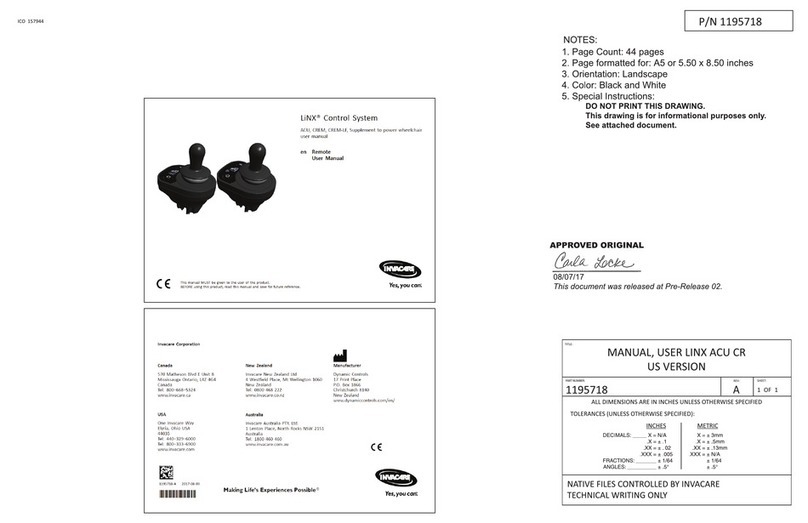
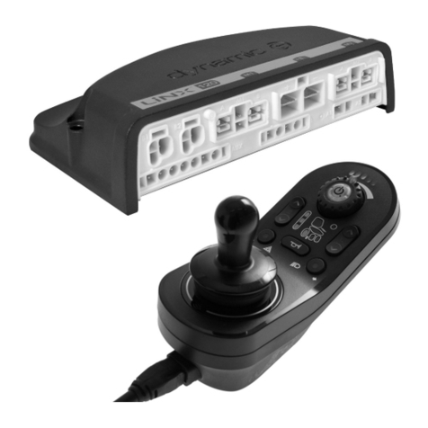
Invacare LiNX REM400 User manual

NOTES:
1. PAGE COUNT - 100
2. PAGE FORMATTED FOR – A4 (8-1/4 x 11-3/4 INCHES)
3. MATERIAL - MINIMUM 60 LB (OR 90 GSM) OFFSET TEXT
4. ORIENTATION - PORTRAIT
5. COLOR - BLACK AND WHITE
6. SPECIAL INSTRUCTIONS -
A. DO NOT PRINT THIS DRAWING.
B. THIS DRAWING IS FOR INFORMATIONAL PURPOSES ONLY.
C. SEE ATTACHED DOCUMENT ARTWORK FOR INSPECTION AND PRINTING.
D. DOCUMENT ARTWORK CONTROLLED BY INVACARE TECHNICAL DOCUMENTATION ONLY.
3RD ANGLE PROJECTION
ANSI/ASME Y14.5M-1994
UNLESS OTHERWISE SPECIFIED
ALL DIMENSIONS ARE IN INCHES UNLESS OTHERWISE SPECIFIED
= CRITICAL QUALITY ATTRIBUTE
= KEY CHARACTERISTIC IDENTIFICATION
PART DESCRIPTION:
MANUAL, USER LINX
DLX-REM400 REMOTE
PART NO.
60126081
REVISION
C
C/N NO.
163206
RELEASED TO PRODUCTION
PRE-RELEASE
REVISION:
00
INVACARE CORP.
ELYRIA, OH.
TEMPLATE
SIZE
: A
SCALE:
1:1
DRAWN BY:
CW
DATE:
02/23/2022
THIS IS THE PROPERTY OF INVACARE CORP. IT MUST NOT BE TRADED OR REPRODUCED IN ANY MANNER, NOR SHALL IT BE SUBMITTED TO OUTSIDE PARTIES FOR EXAMINATION WITHOUT OUR CONSENT. IT SHALL BE USED ONLY AS A MEANS OF REFERENCE TO DO WORK DESIGNED OR FURNISHED BY US. DO NOT SCALE THIS DRAWING.

LiNX® Control System
REM400, Supplement to power wheelchair user manual
en
Remote
User Manual
This manual MUST be given to the user of the product.
BEFORE using this product, this manual MUST be read and saved for future reference.

Contents
1 General 5
1.1 About This Manual 5
1.2 Symbols 5
1.3 Prescription Statement 5
1.4 Intended Use 5
1.4.1 Intended Use—REM 400 5
1.5 Indication for Use 5
1.6 Service Life 5
2 Safety 6
2.1 General Guidelines 6
2.1.1 Live Edit Guidelines 8
2.1.2 Usage Guidelines 8
2.1.3 Setup and Service Guidelines 9
3 Electromagnetic Compatibility (EMC) Information 10
3.1 Electromagnetic Compatibility 10
3.1.1 Minimizing Emissions 10
4 Components 11
4.1 User Interface—REM400 11
4.2 Screen Composition Overview 11
4.2.1 Battery Indicator 11
4.2.2 Status Indicator 12
4.2.3 Profile Name 12
4.2.4 Time 12
4.2.5 Status Information 12
4.3 User Function Screen Overview 13
4.3.1 Left- or Right-Handed 13
4.3.2 Function Screen Header 13
4.3.3 Drive Screen 14
4.3.4 Seating Screen 15
4.3.5 Connectivity Screen 15
4.3.6 Utility Screen 15
4.3.7 Arrangement 16
4.4 Navigation Button 17
4.5 Labels on the Product 17
4.5.1 Labels on Dynamic Controls’ Parts 17
4.5.2 Labels on Toggle Switches 19
4.5.3 Labels on Adaptive Switch Labs Parts 19
4.5.4 Serial Number and Date of Manufacture 20
5 Setup 21
5.1 Connecting the Remote 21
6 Usage 22
6.1 Operating the Remote 22
6.1.1 Powering Up the Remote 22
6.1.2 Powering Down the Remote 22
6.1.3 Setting the Attendant Control 22
6.1.4 Maximum Speed Control 22
6.1.5 Menu Screen Controls 23
Buttons 23
Switches 24
Sliders 24
6.1.6 Menu Screen Settings 25
Menu Structure 25
Menu Screen 26
Settings Menu 26
Display 27
Interaction 27
Audible Cues 28
Connectivity 28
6.1.7 Menu Screen 29
Opening the Menu Screen 29
Closing the Menu Screen 29
Configuring the Menu Screen 29
6.1.8 Configuring the Time 29
6.1.9 Locking the Screen to Avoid Unintentional Response 30
6.2 Navigating User Function Screens 31
6.2.1 Function Change Inhibits 31
6.2.2 Direct Navigation 31
Using Swipe-and-Tap Mode 31
Using Tap Mode 32
Using a Control Input (CI) 33
6.2.3 Indirect Navigation 33
6.2.4 Menu Select 33
Controlling Navigation 33
Navigation Entry 35
Menu Select with 4Q Operation 36
Menu Select with 3Q Operation 36
Menu Select in Grid View 37
Navigation Entry—Menu Select 37
6.2.5 Scan Select Overview 38
Navigation Entry—Menu Select 38
6.2.6 Scan Select 40
Navigation Entry 40
Scan Select with 4Q or 3Q Operation 40
6.3 Using the Multipurpose Buttons 41
6.4 Using the Toggle Switches (Optional) 41
6.5 Using Proportional Driving Mode 41
6.5.1 Joystick 41
Joystick Shaping 42
6.5.2 Maximum Speed Control 42
6.6 Using Latched Driving Mode 43
6.6.1 Turn Commands 44
6.6.2 External Stop Switch 44
External Stop Switch Test 44
6.6.3 1 Step Up 45
Driving 45
Stopping 45
6.6.4 3 Step Up 45
Driving 45
Stopping 45
6.6.5 5 Step Up 46
Driving 46
Stopping 46
6.6.6 3 Step Up/Down 46
Driving 46
Stopping 46
6.6.7 5 Step Up/Down 47
Driving 47
Stopping 47
6.6.8 Cruise Control 47
© 2022 Invacare Corporation
All rights reserved. Republication, duplication or modification in whole or in
part is prohibited without prior written permission from Invacare. Trademarks
are identified by ™ and ®. All trademarks are owned by or licensed to Invacare
Corporation or its subsidiaries unless otherwise noted.
Invacare reserves the right to alter product specifications without further
notice.
Making Life’s Experiences Possible is a registered trademark in the U.S.A.
LiNX is a registered trademark of Dynamic Controls.
Bluetooth is a registered trademark of Bluetooth SIG, Inc.
IOS is a trademark or registered trademark of Cisco in the U.S. and other
countries and is used under license to Apple, Inc.
Android is a trademark of Google, LLC.

Driving 47
Stopping 47
6.7 Using Emergency Stop 47
6.8 Operating the Position Lights 48
6.8.1 Turn On the Position Lights 48
6.8.2 Turn Off the Position Lights 48
6.9 Operating the Hazard Lights 49
6.9.1 Turn On the Hazard Lights 49
6.9.2 Turn Off the Hazard Lights 49
6.10 Operating the Turn Signals 50
6.10.1 Turn On the Turn Signals 50
6.10.2 Turn Off the Turn Signals 51
6.11 Operating the Horn 51
6.12 Operating Lighting Functions and the Horn via the Utility
Function Card 51
6.13 Locking/Unlocking the Remote 52
6.13.1 Locking the Remote 52
6.13.2 Unlocking the Remote 52
6.14 Using Sleep Mode 52
6.15 Using Rest Mode 52
6.15.1 Entering Rest 52
Entering Rest from a Drive or Seating Function via
Timeout 53
Entering Rest from Any Function via Control Input 53
Entering Rest from Menu Select via Timeout 53
Entering Rest from Menu Navigation via Control Input 53
6.15.2 In Rest 53
6.15.3 Exiting Rest 53
6.16 Operating Powered Seating Functions 53
6.16.1 Through Seating Screens 54
Symbols and their Meanings 54
Other Configurations 54
6.16.2 Through External Switches 55
Egg Switch 56
Stereo Toggle Switch 56
Stereo Button Switch 56
4–way Toggle Switch 56
4–way Button Switch 57
10–way Switch 58
6.16.3 Speed Reduction and Seating Function Inhibits 58
Speed Reduction 58
Seating Function Inhibits 59
6.17 Using Connectivity Screens 59
6.17.1 Connectivity Card Configuration 59
Pairing the LiNX System with a User’s Device 59
Pairing a Mobile Device with the LiNX system 60
Pairing a PC or Laptop with a LiNX System 61
Linking the Connectivity Card with the User’s Device 62
Connecting Devices with the LiNX System 63
Removing Paired Devices 63
Selecting a Connectivity Card 64
6.17.2 Mouse Mover 65
Setting up a Mouse Mover 65
Operating the Mouse Mover 67
Moving the Cursor 67
Right or Left Click 67
Scrolling 67
Disconnecting 67
6.18 Using Switch Control 67
6.18.1 Switch Control General Information 67
6.18.2 Switch Control Setup 68
Configuring Switch Control 68
Configuring Switch Control (Android) 68
Configuring Switch Control (iOS) 69
6.18.3 Switch Control Operation 70
Controlling a Mobile Device 70
Disconnecting 70
6.19 Secondary Inputs 71
6.19.1 Using the ASL 128 Molecule Joystick (Chin Control) 71
Driving 71
Moving the Chin Control 71
Changing Function Screens 71
Operating the Lighting Functions and Horn 72
6.19.2 Using the Compact Single Switch Joystick 72
Driving 72
Changing Function Screens 72
Operating the Lighting Functions and Horn 72
6.19.3 Using the Micro Extremity Control joystick 73
Driving 73
Changing Function Screens 73
Operating the Lighting Functions and Horn 73
6.19.4 Using the Pediatric Compact Joystick 73
Changing Function Screens 74
Operating the Lighting Functions and Horn 74
6.19.5 Using the Sip and Puff 74
Driving 74
Stopping 75
Changing Function Screens 75
Operating the Lighting Functions and Horn 75
6.19.6 Using the Sip and Puff Head Array 75
Driving 76
Stopping 76
Changing Function Screens 76
Operating the Lighting Functions and Horn 77
6.19.7 Using the Head Array 77
Driving 78
Changing Function Screens 78
Operating the Lighting Functions and Horn 79
6.19.8 Using the Four-Switch Proximity Array 79
Operating the Lighting Functions and Horn 80
6.19.9 Using the Wireless Mouse Emulator 80
6.20 Disabling Bluetooth 82
6.21 Charging the Batteries 82
6.21.1 Battery Alarms 83
6.22 Using the USB Charger 83
7 Maintenance 85
7.1 Maintenance Information 85
7.2 Setup/Delivery Inspection 85
7.3 User/Attendant Inspection Checklists 85
7.3.1 Inspect/Adjust Weekly 85
7.3.2 Inspect/Adjust Monthly 85
7.3.3 Inspect/Adjust Periodically 85
7.4 Service Inspection 85
7.4.1 Six-Month Inspection 86
7.5 Cleaning 86
7.5.1 Cleaning the Sip and Puff 86
7.6 Replacing the Mouthpiece 87
7.7 Replacing the Saliva Trap 88
8 Troubleshooting 89
8.1 Fault Diagnosis 89
8.1.1 Fault Codes and Diagnosis Codes 89
8.2 OON (“Out Of Neutral”) 90
8.2.1 Drive OON Warning 90
8.2.2 Seating OON Warning 91
8.3 Drive Inhibit Indication 91
9 Technical Data 92
9.1 Technical Specifications 92

9.1.1 Mechanical Specifications 92
9.1.2 Electrical Specifications 92
10 Wireless Technology 93
10.1 Wireless Technology Overview 93
10.2 Intended Wireless (Electromagnetic) Environment 93
10.3 LiNX Wireless Functions 93
10.3.1 Mouse Mover 93
10.3.2 Remote Diagnostics 94
10.3.3 Configuration 94
10.4 Quality of Service 94
10.4.1 Data Integrity 94
10.4.2 Safeguards and Redundancy 95
10.5 Wireless Coexistence 95
10.6 Cybersecurity 95
10.6.1 Cybersecurity Controls 95
10.6.2 User Actions 96
11 Warranty 97
11.1 Limited Warranty—US 97
11.2 Limited Warranty—Canada 97
11.3 Repair or Replacement 97
11.4 Disclaimers 97
11.4.1 Limitations and Exclusions 97

5 60126081-C
1 General
1.1 About This Manual
This document is a supplement to the mobility device’s documentation.
For more information about the product, for example product safety notices and product recalls, contact your local Invacare
representative. Before reading this manual, make sure you have the latest version. You will find the latest version on the Invacare
website. For the address and website see the back page of this manual.
1.2 Symbols
Signal symbols and/or words are used in this manual and apply to hazards or unsafe practices which could result in personal injury
or property damage. See the information below for definitions of the signal words.
DANGER!
-Danger indicates an imminently hazardous situation which, if not avoided, will result in death or serious injury.
WARNING!
-Warning indicates a potentially hazardous situation which, if not avoided, could result in death or serious injury.
CAUTION!
-Caution indicates a potentially hazardous situation which, if not avoided, may result in property damage
or minor injury or both.
-Indicates a hazardous situation that could result in damage to property if it is not avoided.
Gives useful tips, recommendations and information for efficient, trouble-free use.
This symbol identifies a list of various tools, components and items which you will need in order to carry out certain work.
1.3 Prescription Statement
Per 21 CFR 801.109(b)(1) the device is labeled for prescription use only.
CAUTION!
Federal Law (USA) restricts this device to sale by or on the order of a licensed physician.
1.4 Intended Use
Refer to the user manual for the power wheelchair base and for the seating system for the intended use of the mobility
device.
1.4.1 Intended Use—REM 400
The LiNX REM400 is a remote of the LiNX family, intended to allow powered wheelchair users to interact with the LiNX system.
The REM400 remote allows control of drive, actuator, lighting and connectivity functions. It provides an input for battery charging
and contains a Bluetooth interface for connectivity functions only (HID and diagnostics). It is not possible to control the wheelchair
via Bluetooth. The REM400 remote allows the use of alternative drive input controls, such as head controls, and is capable of
providing information about the active user input. It provides an input for battery charging and contains a Bluetooth interface for
connectivity functions only (HID and diagnostics).
1.5 Indication for Use
Refer to the user manual for the base and for the seat for the indication for use for the mobility device.
1.6 Service Life
The expected service life is five years, presuming the product is used daily and in accordance with safety instructions, maintenance
instructions and intended use as stated in this manual.
LiNX® Control System

60126081-C 6
2 Safety
2.1 General Guidelines
The safety section contains important information for the safe operation and use of this product.
Refer to the wheelchair base and seating system user manuals for additional safety and operation information.
WARNING!
Risk of Death, Injury or Damage
Improper use of this product may cause injury or damage.
-If you are unable to understand the warnings, cautions or instructions, contact a health care professional or provider
before attempting to use this equipment.
-DO NOT use this product or any available optional equipment without first completely reading and understanding these
instructions and any additional instructional material such as user manual, service manuals or instruction sheets supplied
with this product or optional equipment.
WARNING!
Risk of Death, Injury or Damage
Continued use of the product with damaged parts could lead to the product malfunctioning and causing injury to the user
and/or caregiver.
-Check all product components and carton for damage and test components before use. In case of damage or if the
product is not working properly, stop using the product and contact a qualified technician or Invacare for repair.
WARNING!
Risk of Injury, Damage or Death
Improper setup, service, adjustment or programming may cause injury, damage or death.
-Qualified technician MUST set up, service and program the wheelchair.
-DO NOT allow non-qualified individuals to perform any work or adjustments on the wheelchair.
-DO NOT set up or service the wheelchair while occupied except for programming or unless otherwise noted.
-Turn off power BEFORE adjusting or servicing the wheelchair. Note that some safety features will be disabled.
-Ensure all hardware is securely tightened after setup, service or adjustments.
-Warranty is void if non-qualified individuals perform any work on this product.
DANGER!
Risk of Death, Serious Injury, or Damage
Continued use of a wheelchair that is not set to the correct specifications may cause erratic behavior of the wheelchair,
resulting in death, serious injury, or damage.
-Performance adjustments should only be made by professionals of the healthcare field or persons fully conversant with
this process and the driver's capabilities.
-After the wheelchair has been set up/adjusted, check to make sure that the wheelchair performs to the specifications
entered during the set up procedure. If the wheelchair does not perform to specifications, turn the wheelchair Off
immediately and reenter set up specifications. Contact Invacare, if wheelchair still does not perform to correct
specifications.
WARNING!
Risk of Injury or Damage
Failure to remove the LiNX Access Key (LAK) from the wheelchair after programming is complete may lead to
unauthorized access to the wheelchair settings.
-Always remove the LAK from the wheelchair when programming is complete.
WARNING!
Risk of Serious Injury or Damage
Use of unapproved accessories may result in serious injury or damage.
-Invacare products are specifically designed and manufactured for use in conjunction with approved Invacare accessories.
Unapproved accessories have not been tested by Invacare and are not recommended for use with Invacare products.
-DO NOT use unapproved accessories.
-To obtain approved Invacare accessories, contact Invacare by phone or at www.invacare.com.
WARNING!
Risk of Serious Injury or Damage
Loss of power due to loose electrical connections could cause the wheelchair to suddenly stop, resulting
in serious injury or damage.
-ALWAYS ensure all electrical connections are tightly connected so they don’t vibrate loose.
2 Safety

7 60126081-C
WARNING!
Risk of Injury or Damage
Connector pins on the cables connected to the power module can still be live even when the system is off. Human contact
or other materials may cause an electrical short. To prevent injury or damage due to electrical shorts:
-Cables with live pins should be connected, restrained or covered (with non-conductive materials) so they are not exposed
to human contact or materials that could cause electrical shorts.
-When cables with live pins have to be disconnected, (for example, when removing the bus cable from the remote for
safety reasons) make sure to restrain or cover the pins (with non-conductive materials).
DANGER!
Risk of Death, Serious Injury, or Damage
Corroded electrical components due to water, liquid exposure, or incontinent users can result in death,
serious injury, or damage.
-Minimize exposure of electrical components to water and/or liquids. Electrical components damaged by corrosion MUST
be replaced immediately.
-Wheelchairs that are used by incontinent users and/or are frequently exposed to water/liquids may require replacement
of electrical components more frequently.
DANGER!
Risk of Death, Serious Injury, or Damage
Lighted cigarettes dropped onto an upholstered seating system can cause a fire, resulting in death,
serious injury, or damage.
Wheelchair occupants are at particular risk of death or serious injury from these fires and resulting fumes because they
may not have the ability to move away from the wheelchair.
-DO NOT smoke while using this wheelchair.
WARNING!
Risk of Injury, Damage or Death
Improper routing of cable(s) may cause a tripping, entanglement or strangulation hazard that may result
in injury, damage or death.
-Ensure all cable(s) are routed and secured properly.
-Ensure there are no loops of excess cable extending away from the chair.
-Close supervision and attention is needed when operating the wheelchair near children, pets or people with
physical/mental disabilities.
WARNING!
Risk of Injury, Damage or Death
Pinched or severed cable(s) may be a shock or fire hazard and may cause injury, damage or death.
-Ensure all cable(s) are routed and secured properly.
-Inspect cable(s) periodically for proper routing, pinching, chafing or other similar wear.
-Replace any damaged cables immediately.
Risk of Damage to the Mobility Device
There are no user-serviceable parts inside any case.
-Do not open or disassemble any case.
As a manufacturer of wheelchairs, Invacare endeavors to supply a wide variety of wheelchairs to meet many needs of the
end user. However, final selection of the type of wheelchair to be used by an individual rests solely with the user and
his/her healthcare professional capable of making such a selection. Invacare recommends working with a qualified rehab
technology provider, such as an ATP, (Assistive Technology Professional).
The information contained in this document is subject to change without notice.
LiNX® Control System

60126081-C 8
2.1.1 Live Edit Guidelines
WARNING!
Risk of Injury or Damage
Rapid and unfamiliar parameter changes may lead to injury or damage.
-Qualified technicians should make the user aware that in live edit mode, the performance of the wheelchair will be
changed instantly.
-After programming in live edit mode, the wheelchair performance should be checked for driving safety. Ensure the
wheelchair performance is appropriate to the capabilities and needs of the user.
-Users should use caution when driving the wheelchair while operating in Live Edit mode.
-Users should use care to stay in the programming range.
-Always perform live edit changes in a safe environment.
Live edit adjustments are best done in an unrestricted but safe area. The presence of an attendant is recommended.
The Bluetooth® range of the programmer is 33 ft (10 m). If the wheelchair drives out of range of the Bluetooth
programmer, the programmer must reconnect before the parameters can be changed.
2.1.2 Usage Guidelines
DANGER!
Risk of Death, Serious Injury, or Damage
Misuse of the wheelchair may cause component failure and/or cause the wheelchair to start smoking, sparking, or
burning. Death, serious injury, or damage may occur due to fire.
-DO NOT use the wheelchair other than its intended purpose. If the wheelchair starts smoking, sparking, or burning,
discontinue using the wheelchair and seek service IMMEDIATELY.
WARNING!
Risk of Injury, Damage or Death
Misuse of wheelchair may result in injury, damage or death.
-Use care when operating the wheelchair on roads, streets or other roadways.
-Use care when operating the wheelchair when vision is impaired by poor lighting such as unlit rooms, during the night or
similar situations.
-ALWAYS be aware of motor vehicles and your surroundings.
WARNING!
Risk of Injury, Damage or Death
Use of the wheelchair while judgment or ability is impaired may result in injury, damage or death.
-DO NOT operate the wheelchair under the influence of alcohol, medications or other substances that
impair judgment or function.
-Changing medications may affect your ability to operate the wheelchair. Discuss the impact on your ability to operate the
wheelchair with a health care professional when changing medications.
-DO NOT operate the wheelchair under conditions where judgment or function may be impaired. This may include but is
not limited to lack of sleep or poor sight.
-Always be aware of your surroundings.
WARNING!
Risk of Injury, Damage or Death
Loss of traction or stability on rough or unstable terrain may cause injury, damage or death.
-Use care when operating the wheelchair on rough or unstable terrain. This would include but is not limited to areas of
rock, mulch, mud, uneven pavement, roots and similar conditions.
-Be aware of your surroundings and conditions that might affect the ability to operate the wheelchair.
WARNING!
Risk of Serious Injury
Impacting objects in the surrounding environment can cause serious injury.
-When maneuvering the wheelchair around, ALWAYS have assured cleared distance with all objects in environment.
CAUTION!
Risk of Injury
The remote module can get hot when exposed to strong sunlight for long periods.
-Do not leave mobility device in direct sunlight for long periods.
DANGER!
Risk of Death, Serious Injury, or Damage
A malfunctioning joystick could cause unintended/erratic movement resulting in death, serious injury, or damage.
-If unintended/erratic movement occurs, stop using the wheelchair immediately and contact a qualified technician.
2 Safety

9 60126081-C
2.1.3 Setup and Service Guidelines
DANGER!
Risk of Death, Serious Injury, or Damage
Use of incorrect or improper replacement (service) parts may cause death, serious injury, or damage.
-Replacement parts MUST match original Invacare parts.
-ALWAYS provide the wheelchair serial number to assist in ordering the correct replacement parts.
WARNING!
Risk of Serious Injury
Sharp edges can cause serious injury.
-Be mindful that some parts may have sharp edges. Use caution when encountering these sharp edges.
WARNING!
Risk of Serious Injury
Hot surfaces can cause severe burns.
-Be mindful of potential hot surfaces and avoid touching.
WARNING!
Risk of Death, Serious Injury, or Damage
An improperly connected joystick could cause loss of power, resulting in death, serious injury, or damage.
-Ensure the joystick is securely connected to controller.
CAUTION!
Risk of Damage
Operating the wheelchair in rain or dampness may cause the wheelchair to malfunction electrically and mechanically or
prematurely rust or may damage the upholstery.
-DO NOT leave the wheelchair in a rain storm of any kind.
-DO NOT use the wheelchair in a shower.
-DO NOT leave the wheelchair in a damp area for any length of time.
-Check to ensure that the battery covers are secured in place, joystick boot is NOT torn or cracked where water can enter
and that all electrical connections are secure at all times. DO NOT use if the joystick boot is torn or cracked. If the joystick
boot becomes torn or cracked, replace IMMEDIATELY.
LiNX® Control System

60126081-C 10
3 Electromagnetic Compatibility (EMC) Information
3.1 Electromagnetic Compatibility
Refer to the power wheelchair base and seating system user manuals for more electromagnetic compatibility information
for your mobility device.
Dynamic Controls Electronic Controllers have been tested on typical, representative vehicles to confirm compliance with the
following appropriate EMC standards:
lUSA: ANSI/RESNA WC-2:2009 Sec 21
lEurope: EN12184:2014, ISO7176 - 21:2009
National and international directives require confirmation of compliance on particular vehicles. Since EMC is dependent on a
particular installation, each variation must be tested. The guidelines in this section are written to assist with meeting EMC
requirements in general.
3.1.1 Minimizing Emissions
To minimize emissions and to maximize the immunity to radiated fields and ESD, follow the wiring recommendations in the LiNX
System Service Manual.
3 Electromagnetic Compatibility (EMC) Information

60126081-C 11
4 Components
4.1 User Interface—REM400
AMultipurpose
buttons
B
ON/OFF
button/Status
LED
CTouch display
DJoystick
EBus socket
FStereo jack
sockets
GInfrared
transmitter
HSpeaker
ICharger socket
JToggle switches
4.2 Screen Composition Overview
ABattery bar
BStatus bar
CUser function screen
DNavigation button
4.2.1 Battery Indicator
The battery indicator provides a graphical display of the battery’s current state of charge and, when a battery charger is connected,
the charging status.
4 Components

12 60126081-C
Battery bar displays green when state of
charge is between 60 and 100%.
Battery bar displays orange when state of
charge is between 20 and 59%.
Battery bar displays red when state of charge
is less than 20%.
Charging.
4.2.2 Status Indicator
AProfile name
BTime
CStatus information
4.2.3 Profile Name
The profile name can be set only by the provider.
4.2.4 Time
The time displays as a 12- or 24-hour clock. It is set using the coordinated universal time (UTC) and an offset based on the location
(country) of the user. The UTC is acquired when a system is connected to a programming and diagnostic tool. The country-based
offset is set through the remote module’s status screen. For more information, refer to 6.1.7 Menu Screen, page 29.
4.2.5 Status Information
Icons indicate the current state of the LiNX system.
Indicates a drive lock-out is active. A drive lock-out is a state that prevents the wheelchair from being driven.
Refer to 6.16.3 Speed Reduction and Seating Function Inhibits, page 58 for more information about lock-outs
and slow-downs.
Indicates a drive slow-down is active. A drive slow-down is a state that prevents the wheelchair from being
driven at the standard speed for safety reasons. Instead, the wheelchair is allowed to drive at a reduced speed
for the duration of the active drive slow-down. Refer to 6.16.3 Speed Reduction and Seating Function Inhibits,
page 58 for more information about lock-outs and slow-downs.
Indicates a fault occurred. The number indicates the type of fault. Refer to 8.1 Fault Diagnosis, page 89for
more information about fault codes.
Indicates a seating lock-out is active. A seating lock-out is a state that prevents the wheelchair’s seating from
being operated. Refer to 6.16.3 Speed Reduction and Seating Function Inhibits, page 58, for more information
about lock-outs and slow-downs.
Indicates Bluetooth connectivity is disabled. Refer to 6.20 Disabling Bluetooth, page 82 for more information
about disabling Bluetooth.
Three battery alarms display on the right side of the status bar. For more information, refer to 6.21.1 Battery Alarms, page 83.
LiNX® Control System

60126081-C 13
4.3 User Function Screen Overview
4.3.1 Left- or Right-Handed
With the LiNX system, it is possible to adjust the function screens for left-handed or right-handed users.
Left-handed Right-handed
In this manual, only right-handed function screens display. All buttons have the same functions for right- and left-handed
users, so the descriptions can be used for left-handed users, too.
4.3.2 Function Screen Header
The function screen type is identified by the color of the function screen header:
lgreen indicates a drive screen
lorange indicates a seating screen
lblue indicates a connectivity screen
lpurple indicates a utility screen
The icon A indicates the type of primary input.
The text B is programmable by your provider and can be used to name the function.
Indicator Meaning
REM400
REM500
REM2xx
ACU
CREM
CREM-LF
4 Components

14 60126081-C
Indicator Meaning
Head Array
Sip and Puff
User Switch
4.3.3 Drive Screen
Drive screens can be preset with different maximum speeds to fit your needs and your environment. For example, a drive screen
with a preset lower maximum speed can be used indoors, and a drive screen with a preset total maximum speed can be used
outdoors. In addition, you can also control the preset maximum speed. Refer to 6.5.2 Maximum Speed Control, page 42.
With a drive screen, you can also sound the horn and operate the lighting functions. Refer to 6.11 Operating the Horn, page 51 and
to 6.8 Operating the Position Lights, page 48.
The function information displays either the latched driving mode (refer to 6.6 Using Latched Driving Mode, page 43 or the Gyro
indication (refer to the following table).
No Symbol No Gyro is connected to the system or enabled for drive function.
Gyro is disabled.
Gyro is enabled.
LiNX® Control System

60126081-C 15
4.3.4 Seating Screen
Seating screens are used to operate the seating functions. Refer to 6.16.1 Through Seating Screens, page 54.
4.3.5 Connectivity Screen
Connectivity screens allow you to communicate with external devices. The connectivity function included on your remote is a
mouse mover. The mouse mover allows you to control the cursor on a PC or laptop screen with a user input on the wheelchair, such
as the joystick on the remote module or buttons connected via control inputs. For more information about Connectivity screens and
how to use them, refer to 6.17 Using Connectivity Screens, page 59.
4.3.6 Utility Screen
Fig. 4-1 Example three-quadrant (3Q) navigation utility screen Fig. 4-2 Example four-quadrant (4Q) navigation utility screen
4 Components

16 60126081-C
The utility screen allows you to operate system controls (such as the lighting functions and the horn), as well as control outputs with
external inputs. The Utility screen function is suitable for both three-quadrant (3Q) and four-quadrant (4Q) inputs.
The utility screen allows you to operate two controls/outputs per quadrant, according to the duration the user input is activated:
lA Short/Momentary press
lB Long press
By default, this function is enabled only for chair configurations with an external control input that will not allow the control of the
horn or lights. Contact your provider to change the configuration and to set your desired operations.
For an example of how to use a utility screen in daily use, see 6.12 Operating Lighting Functions and the Horn via the Utility Function
Card, page 51.
4.3.7 Arrangement
Function Screens
F1 F2 F3 F4 F5 F6
Profiles
P1
P2
P3
P4
User function screens are arranged in rows of profiles. Each profile can hold user function screens, which can be of the same type.
For example, a profile can include all drive screens or can be a mixture of drive, seating and connectivity screens.
The maximum number of function screens across all profiles is 40. For example, a configuration with five profiles can hold up to
eight function screens.
LiNX® Control System

60126081-C 17
4.4 Navigation Button
Depending on the configuration of the remote module and the user’s needs, the navigation button displays on the bottom-left or
bottom-right of the screen.
When activated, the navigation button changes color from grey to blue.
The navigation button has two important functions:
1. A visual indication of the configured interaction mode.
Configured for swipe-and-tap actions
This means swiping and tapping the screen activates different functions.
Configured for tap actions
This means only tapping the screen activates different functions. Swipe inputs are ignored.
For more information about changing the interaction mode, refer to 6.1.7 Menu Screen, page 29.
2. A navigation function, depending on context and activation duration. For example, while viewing an active user function
screen, a short press on the Navigation button opens the screen preview display. Refer to 6.2 Navigating User Function
Screens, page 31. A long press opens the status screen. Refer to 6.1.7 Menu Screen, page 29.
External inputs can also be used to interact with the system. Refer to 6.19 Secondary Inputs, page 71.
4.5 Labels on the Product
4.5.1 Labels on Dynamic Controls’ Parts
Labels of Dynamic Controls' parts are located on the rear side of the part. Depending on the part, not all labels are available.
Fig. 4-3 Rear side of the DLX-REM400 Fig. 4-4 Rear side of the DLX-IN400 input module
4 Components

18 60126081-C
A
Product label:
1. Part number
2. Dynamic Controls logo
3. Dynamic Controls part description
4. Dynamic Controls website address
5. Serial number
6. Warning to read manual before use
7. Ingress protection rating
8. WEEE symbol
B
Hardware and application firmware version label:
1. Hardware version
2. Hardware major version
3. Hardware minor version
4. Application version
5. Application major version
6. Application minor version
C
Product label:
lDynamic Controls logo
lProduct bar code
lProduct serial number
lProduct part number
DTamper-evident seal
E
Waste Electrical and Electronic Equipment Directive (WEEE) symbol.
This product has been supplied from an environmentally aware
manufacturer. This product may contain substances that could be
harmful to the environment if disposed of in places (landfills) that are not
appropriate according to legislation.
lThe ‘crossed-out-wheelie-bin’ symbol is placed on this product to
encourage you to recycle wherever possible.
lPlease be environmentally responsible and recycle this product
through your recycling facility at its end of life.
FIPX4 Enclosure ingress protection rating
G
READ INSTALLATION MANUAL BEFORE USE
Recommendation to read the instruction manual before using the
module.
LiNX® Control System

60126081-C 19
H
Product label containing:
lDynamic Controls website address
lDynamic Controls Bluetooth registration
4.5.2 Labels on Toggle Switches
A
Power
Speed pot left
Speed pot right
Function and profile
Seating
Blank
4.5.3 Labels on Adaptive Switch Labs Parts
Labels of Adaptive Switch Labs parts are located either on the left rear side of the part (head arrays) or on the interface box.
Depending on the part, not all labels are available.
4 Components
Other manuals for LiNX REM400
1
This manual suits for next models
1
Table of contents
Other Invacare Control System manuals