INVT Photovoltaic Grid-connected Inverter User manual

Operation Manual
Photovoltaic Grid-connected Inverter
INVT Solar Technology (Shenzhen) Co., Ltd.


1
Preface
The manual is intended to provide detailed information of product information, installation,
application, trouble shooting, precautions and maintenance of iMars series grid-tied solar inverters.
The manual does not contain all the information of the photovoltaic system. Please read this
manual carefully and follow all safety precautions seriously before any moving, installation,
operation and maintenance to ensure correct use and high performance of operation on the
inverter.
The use of the iMars series grid-tied solar inverters must comply with local laws and regulations on
grid-tied power generation.
The manual needs to be kept well and be available at all times.
All rights reserved. The contents in this document are subject to change without notice.
There may be data deviation because of product improving. Detailed information is in accordant
with the final product.

Three-phase photovoltaic grid-connected inverter Content
2
Content
Preface................................................................................................................................................1
Content ...............................................................................................................................................2
1 Safety precautions .........................................................................................................................4
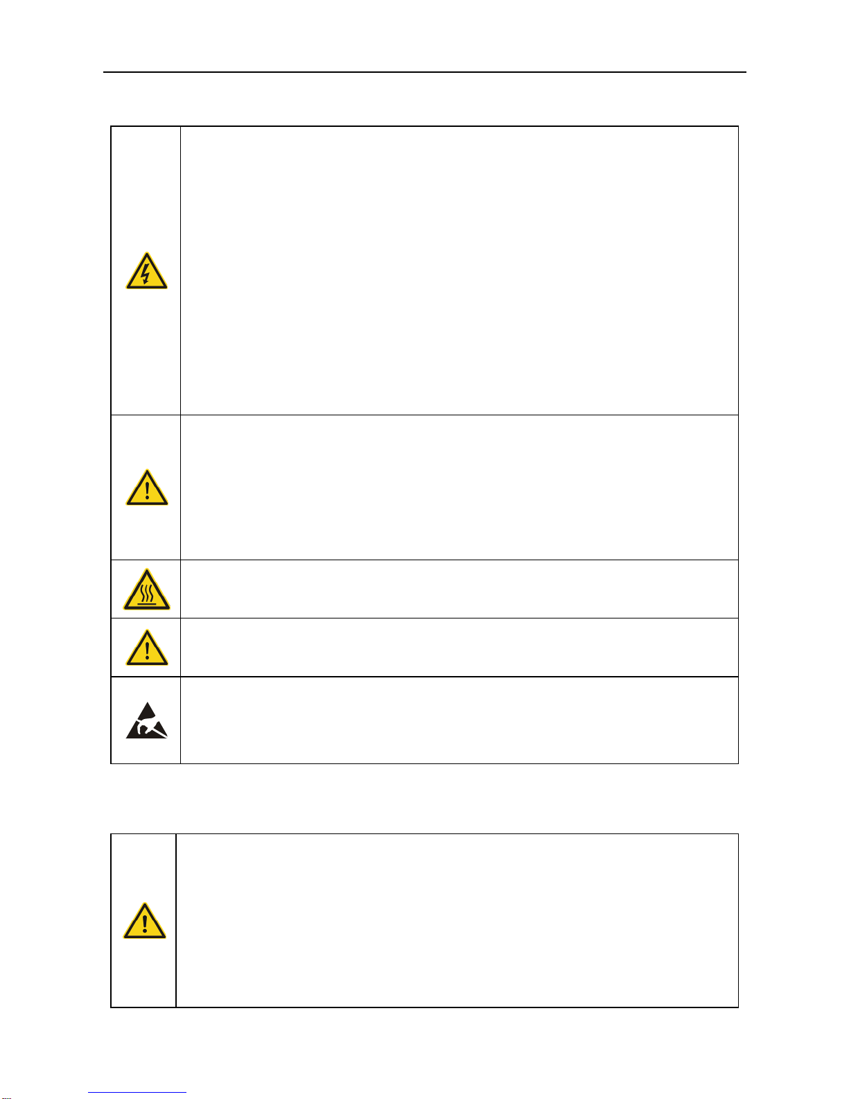
1.1 Warning marks.........................................................................................................................................5
1.2 Safety guidance.......................................................................................................................................6
1.2.1 Transport and installation.............................................................................................................6
1.2.2 Grid-connected operation ............................................................................................................7
1.2.3 Maintenance and inspection........................................................................................................8
1.2.4 Waste disposal...............................................................................................................................8
2 Product overview ...........................................................................................................................9
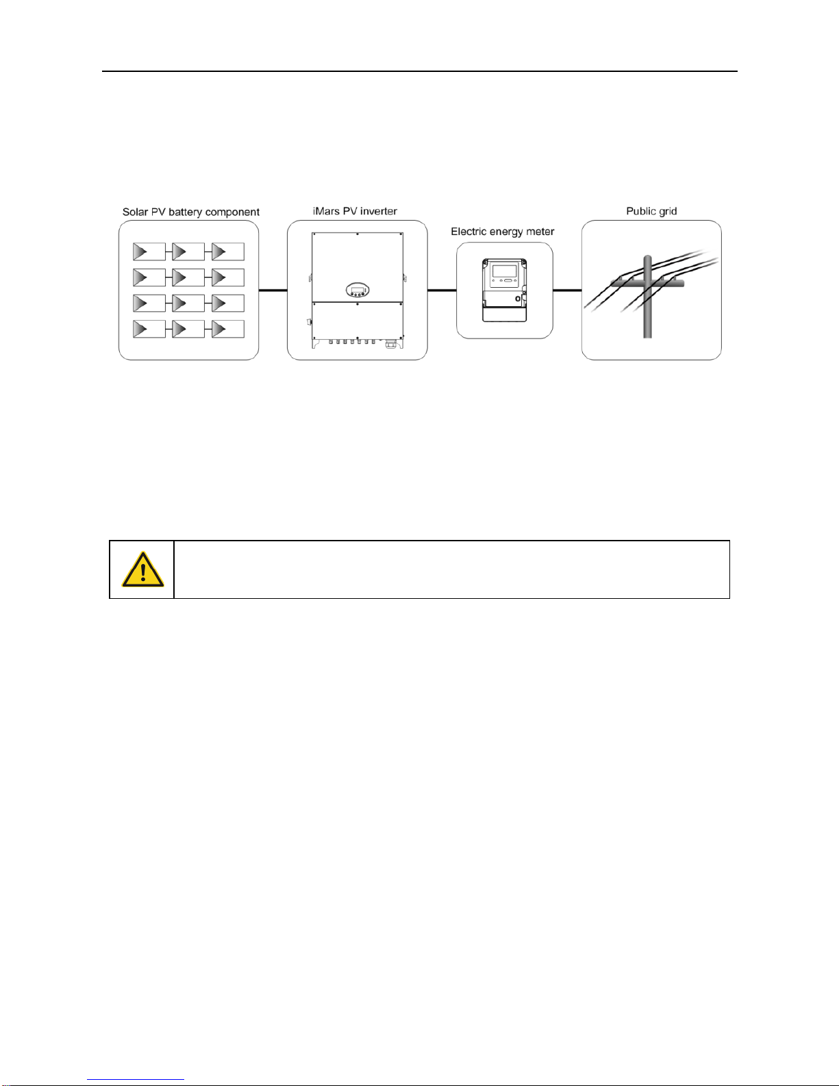
2.1 PV grid-connected power generation system................................................................................ 10
2.1.2 Supported grid connection structure ...................................................................................... 10
2.2 Product appearance............................................................................................................................ 11
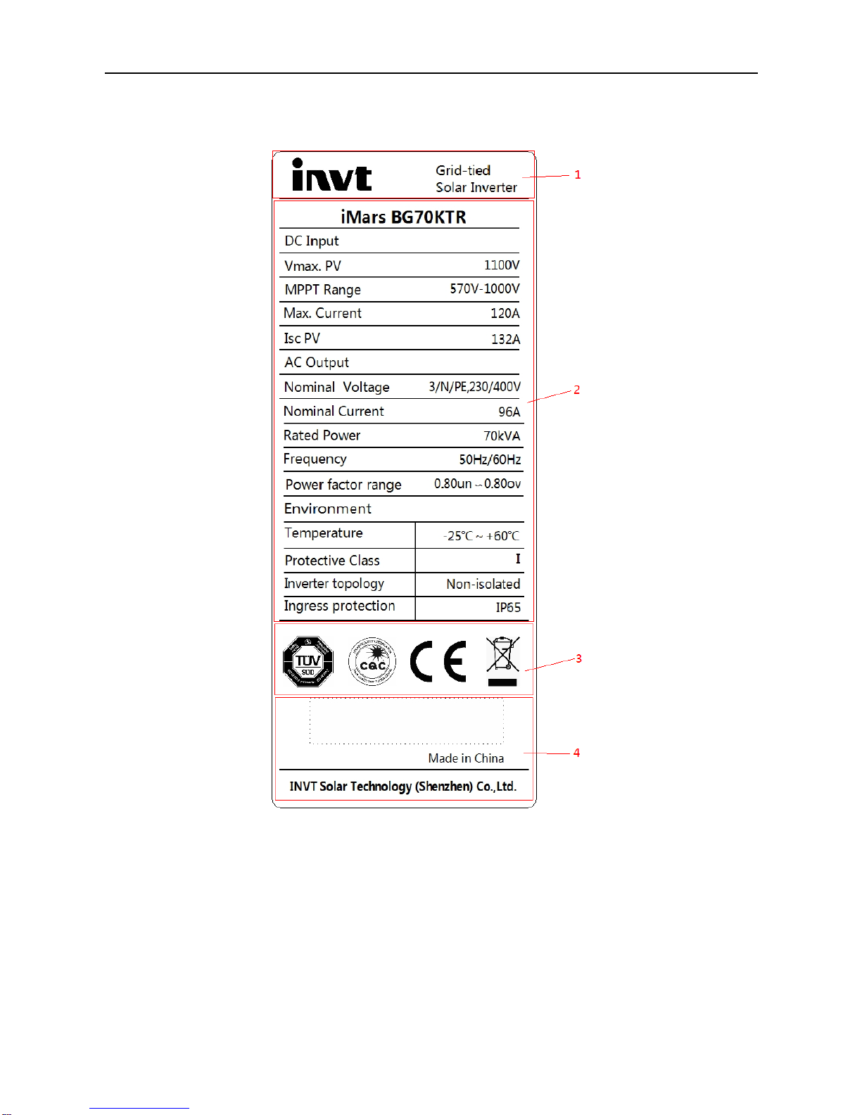
2.3 Nameplate ............................................................................................................................................. 13
2.4 Product model....................................................................................................................................... 14
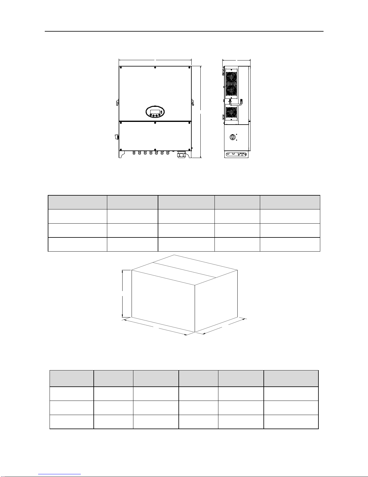
2.5 Outline dimension and weight........................................................................................................... 15
3 Storage.............................................................................................................................................16
4 Installation .......................................................................................................................................17
4.1 Unpacking confirmation...................................................................................................................... 18
4.2 Preparation before installation .......................................................................................................... 19
4.2.1 Installation tool............................................................................................................................. 19
4.2.2 Installation site............................................................................................................................. 20
4.2.3 Specification of leads................................................................................................................. 22
4.2.4 Micro breaker............................................................................................................................... 23
4.3 Mechanical installation........................................................................................................................ 23
4.3.1 Installation of three-phase inverter ......................................................................................... 24
4.4 Electrical connection ........................................................................................................................... 27
4.4.1 Connection of photovoltaic string............................................................................................ 27
4.4.2 Three-phase inverter grid connection .................................................................................... 31
5 Running .........................................................................................................................................33

Three-phase photovoltaic grid-connected inverter Content
3
5.1 Inspection before running................................................................................................................... 34
5.2 Inverter grid-connected running........................................................................................................ 34
5.3 Inverter stop .......................................................................................................................................... 35
5.4 Daily maintenance and inspection ................................................................................................... 35
5.4.1 Periodic maintenance on the inverter..................................................................................... 36
5.4.2 Maintenance guidance .............................................................................................................. 37
6 Display operation panel...............................................................................................................42
6.1 LED state indicator .............................................................................................................................. 43
6.2 Operation keypad................................................................................................................................. 45
6.3 LCD panel.............................................................................................................................................. 45
6.4 Function operation............................................................................................................................... 46
6.4.1 Monitoring parameter................................................................................................................. 46
6.4.2 Historical records ........................................................................................................................ 48
6.4.3 Statistic information.................................................................................................................... 48
6.4.4 Parameter setup.......................................................................................................................... 48
6.4.5 System information..................................................................................................................... 57
6.4.6 Present fault................................................................................................................................. 57
6.4.7 Inverter control............................................................................................................................. 57
6.4.8 Mode setup................................................................................................................................... 59
6.5 Selection of grid certification standard............................................................................................ 59
7 Monitoring communication.........................................................................................................61
7.1 Standard communication.................................................................................................................... 62
7.2 Optional communication..................................................................................................................... 63
8 Fault isolation ...............................................................................................................................65
9 Contact us .....................................................................................................................................69
10 Appendix......................................................................................................................................70

Three-phase photovoltaic grid-connected inverter Safety precautions
4
1 Safety precautions
iMars series grid-tied solar inverters are designed and tested strictly in accordance with relevant
international safety standards. As an electrical and electronic device, all relevant safety regulations
must be strictly complied during installation, operation, and maintenance. Incorrect use or misuse
may result in:
Injury to the life and personal safety of the operator or other people.
Damage to the inverter or other property belonging to the operator or other people.
In order to avoid personal injury, damage to the inverter or other devices, please strictly observe
the following safety precautions.
This chapter mainly describes various warning symbols in operation manual and provides safety
instructions for the installation, operation, maintenance and use of the iMars series grid-tied solar
inverters.

Three-phase photovoltaic grid-connected inverter Safety precautions
5
1.1 Warning marks
Warning marks inform users of conditions which can cause serious physical injury or death, or
damage to the device. They also tell users how to prevent the dangers. The warning marks used in
this operation manual are shown below:
Mark
Name
Instruction
Abbreviation
Danger
Danger
Serious physical injury or even death may occur
if not follow relevant requirements.
Warning
Warning
Physical injury or damage to the device may
occur if not follow relevant requirements.
Forbid
Electrostatic
sensitive
Damage may occur if relevant requirements are
not followed.
Hot
High
temperature
Do not touch the base of the inverter as it will
become hot.
Note
Note
The procedures taken for ensuring proper
operation.
Note
Grounding
The inverter must be reliably grounded.
Discharge
Ensure that DC and AC side circuit breakers
have been disconnected and wait at least 5
minutes before wiring and checking.
Note: Technical personnel who can perform installation, wiring,
commissioning, maintenance, troubleshooting and replacement of the iMars
series grid-tied solar inverters must meet the following requirements:
Operators need professional training.
Operators must read this manual completely and master the related safety precautions.
Operators need to be familiar with the relevant safety regulations for electrical systems.
Operators need to be fully familiar with the composition and operating principle of the entire
grid-tied photovoltaic power generation system and related standards of the
countries/regions in which the project is located.
Operators must wear personal protective equipment.

Three-phase photovoltaic grid-connected inverter Safety precautions
6
1.2 Safety guidance
After receiving this product, first confirm the product package is intact. If any
question, contact the logistic company or local distributor immediately.
The installation and operation of PV inverter must be carried out by professional
technicians who have received professional trainings and thoroughly familiar
with all the contents in this manual and the safety requirements of the electrical
system.
Do not carry out connection/disconnection, unpacking inspection and unit
replacement operations on the inverter when power source is applied. Before
wiring and inspection, users must confirm the breakers on DC and AC side are
disconnected and wait for at least 5 minutes.
Ensure there is no strong electromagnetic interference caused by other
electronic or electrical devices around the installation site.
Donot refit the inverter unless authorized.
All the electrical installation must conform to local and national electrical
standards.
Do not touch the housing of the inverter or the radiator to avoid scald as they
may become hot during operation
Ground with proper technics before operation.
Do not open the surface cover of the inverter unless authorized. The electronic
components inside the inverter are electrostatic sensitive. Do take proper
anti-electrostatic measures during authorized operation.
1.2.1 Transport and installation
During storage or transport, ensure the inverter package and the chassis is
intact, dry and clean.
The movement and installation of the inverter require at least two persons due to
its heavy weight.
Select proper tools for movement and installation to ensure the inverter can
operate normally and avoid physical injury. The installation personnel must take

Three-phase photovoltaic grid-connected inverter Safety precautions
7
mechanical protective measures such as wearing anti-drop shoes or working
clothes to protect physical security.
The inverter must be installed by professional technicians.
Do not store or install the inverter on flammable and combustible objects; keep
the inverter away from flammable and combustible objects.
Do not install the inverter in places easily accessible to children or other public.
Remove the metal accessories in hands eg ring or bracelet before device
installation and electrical connection to avoid electric shock.
The solar battery component exposed to the sunlight may generate dangerous
voltage. Users must cover the battery component with fully-lightproof materials
before electrical connection
The inverter input voltage cannot exceed the max input voltage, otherwise the
inverter may be damaged.
PV grid-connected inverter is not applicable to the positive or negative ground
system of solar battery component.
Ensure inverter PE is grounded properly, otherwise the inverter cannot run
normally.
Ensure the inverter is installed firmly and electrical wiring is reliable.
Note: PV grid-connected inverter is only suitable for crystalline silicon-type solar battery
component.
1.2.2 Grid-connected operation
Permissions by local electric power agency must be obtained and the inverter
grid-connected power generation operation must be done by professional
technicians.
All electrical connections must meet the electrical standards of the
countries/regions in which the project is located.
Ensure the inverter is installed firmly and electrical wiring is reliable before
operating on the inverter.
Do not open the housing of the inverter when the inverter is working or powered
up.

Three-phase photovoltaic grid-connected inverter Safety precautions
8
1.2.3 Maintenance and inspection
The maintenance, inspection and repair of the inverter must be done by well
trained and qualified professional technicians.
Contact distributors and manufactures for repair of the inverter.
In order to avoid irrelevant personnel from entering the maintenance area during
maintenance, temporary warning labels must be placed to warn
non-professionals to enter or use fence for isolation.
Before carrying out any maintenance operations, users must disconnect the
breaker on grid side, then disconnect the breaker connected to the PV
component and wait for at least 5 minutes until the internal parts of the inverter
are fully discharged.
The internal of the inverter are mostly electrostatic-sensitive circuits and parts,
users must follow electrostatic protection protocols and take anti-electrostatic
measures.
Do not use components provided by other companies when repairing the inverter.
The inverter can be started again for grid-connected power generation only after
confirming there is no fault that may impact the safety performance of the inverter.
Do not get close to or touch the grid or any metal conductive parts in the PV
power generation system during operation, otherwise electric shock or fire may
occur. Take note of any safety marks and instructions similar to “Danger, electric
shock risk”.
1.2.4 Waste disposal
Do not dispose of the inverter together with household waste. The user has the
responsibility and obligation to send it to the designated organization for recycling
and disposal.

Three-phase photovoltaic grid-connected inverter Product overview
9
2 Product overview
This chapter mainly describes the appearance, package accessories, nameplate and technical
parameters of the grid-connected inverter.

Three-phase photovoltaic grid-connected inverter Product overview
10
2.1 PV grid-connected power generation system
PV grid-connected power generation system is comprised of solar battery component,
grid-connected inverter, power energy gauging device and public grid.
Fig 2.1 Application of PV grid-connected inverter
The PV grid-connected inverter is the core part of solar PV grid-connected power generation
system. The sunlight can be converted to DC energy through PV component, then it is converted
to the sine AC current which has the same frequency and phase position with the public grid via
photovoltaic grid-connected inverter, and feedback such energy to the grid.
It is recommended that the PV array to be installed conforms to IEC 61730 class
Astandards.
2.1.2 Supported grid connection structure
iMars series grid-tied solar inverters support TN-S, TN-C, TN-C-S , TT and IT grid connection.
When applied to the TT connection, the N-to-PE voltage should be less than 30V.

Three-phase photovoltaic grid-connected inverter Product overview
11
Figure 2.2 Type of grid
2.2 Product appearance
Fig 2.3 Appearance of 40-70kW three-phase PV inverter
Table 2-1 Instruction for key cosmetic parts of three-phase PV inverter

Three-phase photovoltaic grid-connected inverter Product overview
12
No
Name
Instruction
1
Display operation panel
LED state indicator
2
Surface cover
3
DC input interface
Inverter DC input port, connect to PV array
4
Communication
interface
RS485 communication interface and its extension port EXT
5
AC terminal
Inverter AC output port, connect to public grid
6
Hanging slot
The docking port between inverter master and installation
bracket
7
Handle
The force bearing point when moving the inverter
8
Safety precautions
9
Nameplate
Indicate the rated inverter parameters
10
Anti-theft screw hole
Used to fix the inverter to the installation bracket
11
Fan installation
component
Air inlet port, used to fix the fan
12
DC switch
Switch on or switch off DC input

Three-phase photovoltaic grid-connected inverter Product overview
13
2.3 Nameplate
Figure 2.4 shows the inverter nameplate.
Figure 2.4 Inverter nameplate
(1)Trademark and product type
(2)Model and important technical parameters
(3)Certification system of the inverter confirming
(4)Serial number, company name and country of origin

Three-phase photovoltaic grid-connected inverter Product overview
14
Icons
Instruction
TUV certification mark. The inverter is certified by TUV.
CE certification mark. The inverter complies with the CE directive.
CQC certification mark. The inverter passed CQC certification.
EU WEEE mark. The inverter cannot be disposed of as domestic waste.
2.4 Product model
Table 2-3 Models of three-phase PV grid-connected inverter
Product name
Model
Rated output power
(W)
three-phase(L1, L2, L3, N, PE)
three-phase photovoltaic grid-connected inverter
40kW
40kW
three -phase photovoltaic grid-connected inverter
50kW
50kW
three -phase photovoltaic grid-connected inverter
60kW
60kW
three -phase photovoltaic grid-connected inverter
70kW
66kW
three -phase photovoltaic grid-connected inverter
50KW -HV
50KW
three -phase photovoltaic grid-connected inverter
70KW -HV
70KW
Note: Technical parameters of iMars series inverter refers to appendix

Three-phase photovoltaic grid-connected inverter Product overview
15
2.5 Outline dimension and weight
DW
H
Fig 2.6 Outline dimension of the inverter
Table 2-4 Dimension and net weight of the inverter
Model
Height(mm)
Width(mm)
Depth(mm)
Net weight(kg)
40-70kW
810
645
235
52
70kW -HV
810
645
235
52
50kW-HV
660
645
255
55
W
H
D
Fig 2.6 Dimension of paper package
Table 2-5 Package dimension and gross weight
Model
Height
(mm)
Width
(mm)
Depth
(mm)
Weight
(kg)
Package
material
40-70kW
990
810
420
62
K3K
70kW -HV
990
810
420
62
K3K
50kW-HV
835
815
410
60
K2K

Three-phase photovoltaic grid-connected inverter Storage
16
3 Storage
If the inverter is not put into use immediately, the storage of inverter should meet the following
requirements:
Do not remove the outer packing.
The inverter needs to be stored in a clean and dry place, and prevent the erosion of dust and
water vapor.
The storage temperature should be kept at -40°C~+70°C, and the relative humidity should
be kept at 5%RH~95%RH.
The stacking of inverters is recommended to be placed according to the number of stacking
layers in the original shipment. Place the inverter carefully during stacking to avoid personal
injury or equipment damage caused by the falling of equipment.
Keep away from chemically corrosive substances that may corrode the inverter.
Periodic inspections are required. If damages are found by worms and rats, or packaging
are found to be damaged, the packaging materials must be replaced in time.
After long-term storage, inverters need to be inspected and tested by qualified personnel
before put into use.

Three-phase photovoltaic grid-connected inverter Installation
17
4 Installation
This chapter describes how to install the inverter and connect it to the grid-tied solar system (including the
connection between solar modules, public grid and inverter).
Read this chapter carefully and ensure all installation requirements are met before installation. Only
qualified electricians are allowed to install the inverter.

Three-phase photovoltaic grid-connected inverter Installation
18
4.1 Unpacking confirmation
The inverter has been thoroughly tested and rigorously checked before delivery, but damage may
still occur during transportation. Before unpacking, check carefully whether the product information
in the order is consistent with that on the nameplate of the package box and whether the product
package is intact. If any damage is detected, please contact the shipping company or the supplier
directly. Please also provide photos of the damage to get our fastest and best service.
Store the idled inverter in its original package and take anti-moisture and anti-dust measures.
After taking the inverter out of the box, check the following items:
(1) Confirm the main body of the inverter is intact and free from any damage;
(2) Confirm there is operation manual, interface accessories and installation accessories
inside the package box;
(3) Confirm the deliverables inside the package box are intact and complete;
(4) Check whether the product information in the order is consistent with that on the inverter
nameplate;
(5) The standard delivery list is shown below.
Standard deliverables of three-phase inverter:
Fig 4.1 Deliverables of 40–70kW three-phase inverter
Table of contents
Other INVT Inverter manuals

INVT
INVT XD Series User manual

INVT
INVT Goodrive 35 Series User manual

INVT
INVT Goodrive600 Series User manual

INVT
INVT XG3-10KTL User manual

INVT
INVT CHV100 Series User manual

INVT
INVT XG25-40KTR User manual

INVT
INVT Goodrive 200 User manual

INVT
INVT Goodrive350-19 Series User manual

INVT
INVT iMars User manual

INVT
INVT Goodrive 800 Series User manual

INVT
INVT Goodrive 300-16 User manual

INVT
INVT Goodrive 300 User manual

INVT
INVT iMars BG12KTR User manual

INVT
INVT CHV180 series User manual

INVT
INVT Goodrive300-19 Series User manual

INVT
INVT XD5KTR User manual

INVT
INVT CHV180-004G-4 User manual

INVT
INVT GD200-037G/045P-4 User manual

INVT
INVT CHF100A-1R5G-S2 User manual

INVT
INVT Goodrive 200 User manual