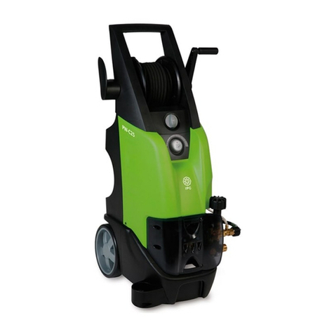
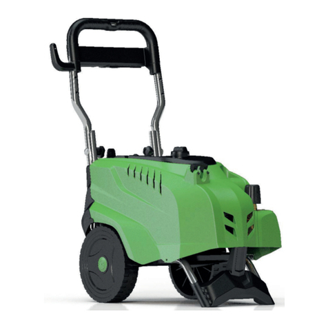
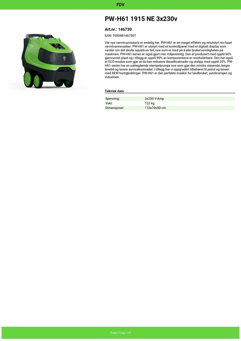
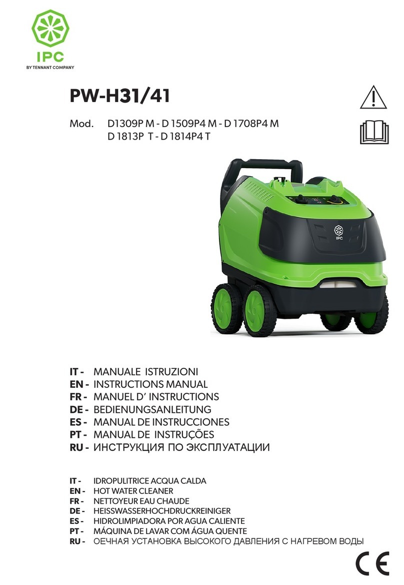
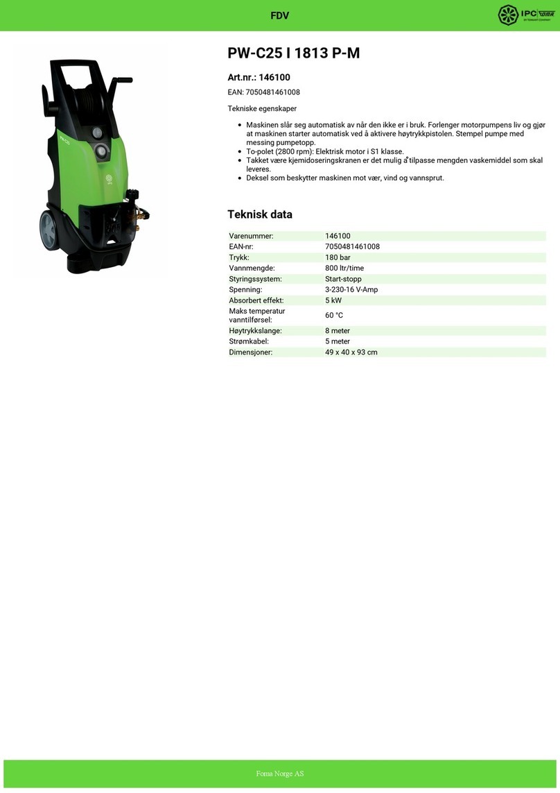
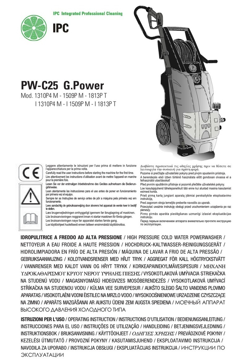
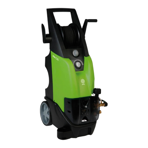
IPC PW-C23 User manual

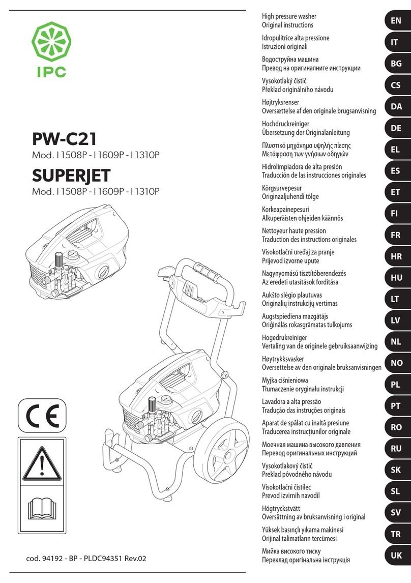
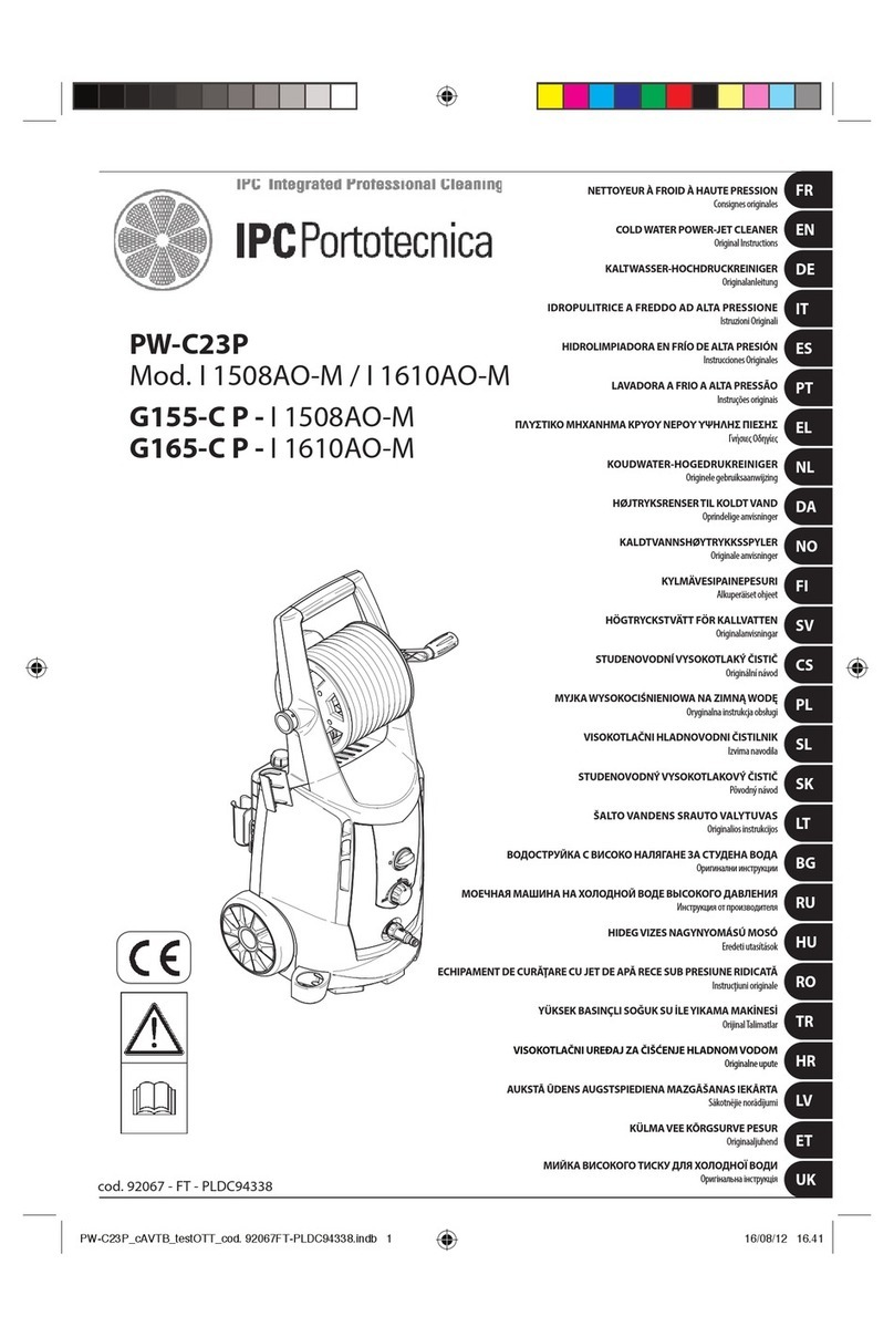
PW-C23
Mod. I 1508AO-M / I 1610AO-M
G155-C - I 1508AO-M
G165-C - I 1610AO-M
cod. 92066 - FT - PLDC94337
NETTOYEUR À FROID À HAUTE PRESSION
Consignes originales
COLD WATER POWER-JET CLEANER
Original Instructions
KALTWASSER-HOCHDRUCKREINIGER
Originalanleitung
IDROPULITRICE A FREDDO AD ALTA PRESSIONE
Istruzioni Originali
HIDROLIMPIADORA EN FRÍO DE ALTA PRESIÓN
Instrucciones Originales
LAVADORA A FRIO A ALTA PRESSÃO
Instruções originais
ΠΛΥΣΤΙΚΟ ΜΗΧΑΝΗΜΑ ΚΡΥΟΥ ΝΕΡΟΥ ΥΨΗΛΗΣ ΠΙΕΣΗΣ
Γνήσιε Οδηγίε
KOUDWATER-HOGEDRUKREINIGER
Originele gebruiksaanwijzing
HØJTRYKSRENSERTIL KOLDT VAND
Oprindelige anvisninger
KALDTVANNSHØYTRYKKSSPYLER
Originale anvisninger
KYLMÄVESIPAINEPESURI
Alkuperäiset ohjeet
HÖGTRYCKSTVÄTT FÖR KALLVATTEN
Originalanvisningar
STUDENOVODNÍVYSOKOTLAKÝ ČISTIČ
Originální návod
MYJKAWYSOKOCIŚNIENIOWA NA ZIMNĄWODĘ
Oryginalna instrukcja obsługi
VISOKOTLAČNI HLADNOVODNI ČISTILNIK
Izvirna navodila
STUDENOVODNÝVYSOKOTLAKOVÝ ČISTIČ
Pôvodný návod
ŠALTO VANDENS SRAUTO VALYTUVAS
Originalios instrukcijos
ВОДОСТРУЙКА С ВИСОКО НАЛЯГАНЕ ЗА СТУДЕНА ВОДА
МОЕЧНАЯ МАШИНА НА ХОЛОДНОЙ ВОДЕ ВЫСОКОГО ДАВЛЕНИЯ
HIDEGVIZES NAGYNYOMÁSÚ MOSÓ
Eredeti utasítások
ECHIPAMENT DE CURĂŢARE CU JET DE APĂ RECE SUB PRESIUNE RIDICATĂ
Instruciuni originale
YÜKSEK BASINÇLI SOĞUK SU İLEYIKAMA MAKİNESİ
OrjnalTalmatlar
VISOKOTLAČNI UREĐAJ ZA ČIŠĆENJE HLADNOM VODOM
Originalne upute
AUKSTĀ ŪDENS AUGSTSPIEDIENA MAZGĀŠANAS IEKĀRTA
Sākotnējie norādījumi
KÜLMA VEE KÕRGSURVE PESUR
Originaaljuhend
МИЙКА ВИСОКОГО ТИСКУ ДЛЯ ХОЛОДНОЇ ВОДИ
FR
EN
DE
IT
ES
PT
EL
NL
DA
NO
FI
SV
CS
PL
SL
SK
LT
BG
RU
HU
RO
TR
HR
LV
ET
UK
©±¥£¤
£±¢
ɂɇɋɌɊɍɄɐɂɂɉɈɗɄɋɉɅɍȺɌȺɐɂɂ
©±¥£¤
£±¢
ɂɇɋɌɊɍɄɐɂɂɉɈɗɄɋɉɅɍȺɌȺɐɂɂ
PW-C23_sAVTB_test OTT_cod. 92066FT-PLDC94337.indb 1 16/08/12 16.39

2
FR Lire attentivement les instructions avant la première utilisation de l'appareil.
EN Read the instructions for use carefully before putting the appliance into operation for the first time.
DE Vor der ersten Inbetriebnahme des Geräts die Betriebsanleitung sorgfältig durchlesen.
IT Leggere attentamente le istruzioni per l'uso prima di mettere in funzione l'apparecchiatura per la prima volta.
ES Léanse atentamente las instrucciones de uso antes de poner en funcionamiento este equipo por primera vez.
PT Leia atentamente as instruções de uso antes de accionar o equipamento pela primeira vez.
EL Διαβάστε προσεκτικά τις οδηγίες χρήσης πριν θέσετε σε λειτουργία το μηχάνημα για πρώτη φορά.
NL Lees de gebruiksaanwijzing aandachtig door voordat u het apparaat voor de eerste keer in werking stelt.
DA Læs venligst brugsanvisningen grundigt igennem, før du anvender enheden for første gang.
NO Les nøye gjennom bruksanvisningen før du tar produktet i bruk for første gang.
FI Lukekaa ohjeet huolellisesti ennen laitteen ensimmäistä käyttöönottoa.
SV Läs användarhandboken noggrant innan du använder högtryckstvättet första gången.
CS Před prvním uvedením zařízení do provozu si pečlivě přečtěte návod k obsluze.
PL Przed uruchomieniem urządzenia po raz pierwszy należy uważnie zapoznać się z treścią niniejszej instrukcji obsługi.
SL Pred prvo uporabo naprave temeljito preberite navodila za uporabo.
SK Pred prvým uvedením spotrebiča do prevádzky si pozorne prečítajte návod.
LT Prieš naudodami įrenginį pirmą kartą atidžiai perskaitykite naudojimo instrukcijas.
BG Прочетете внимателно инструкциите за употреба преди пускането на уреда в експлоатация за първи път.
RU Внимательно прочесть инструкцию перед первым применением устройства.
HU A készülék üzembe helyezése elõtt körültekintõen olvassa át a használati útmutatót.
RO Citiţi cu atenţie instrucţiunile, înainte de prima punere în funcţiune a echipamentului.
TR Aparatı ilk defa çalıştırmadan önce, kullanım kılavuzunda kapsanılan talimatları dikkatle okuyun.
HR Prije prvog pokretanja uređaja pažljivo pročitajte upute za uporabu.
LV Pirms darba uzsākšanas ar šo iekārtu pilnībā jāiepazīstas ar lietotāja pamācību.
ET Lugege hoolikalt kasutusjuhendit enne masina esmakordset kasutust.
UK Уважно прочитайте інструкцію з експлуатації, перш ніж почати користуватися пристроєм.
PW-C23_sAVTB_test OTT_cod. 92066FT-PLDC94337.indb 2 16/08/12 16.39

3
1
E3 E1
A1-A2-A3-A4
C1
B4
B1
C2
B3
D
PW-C23_sAVTB_test OTT_cod. 92066FT-PLDC94337.indb 3 16/08/12 16.39

4
2
7
1
6
3
Ø13
2
4
PW-C23_sAVTB_test OTT_cod. 92066FT-PLDC94337.indb 4 16/08/12 16.39

5
3
4
H
HH
E
E
I
D
2
1
D
2
I
1
F
F
PW-C23_sAVTB_test OTT_cod. 92066FT-PLDC94337.indb 5 16/08/12 16.39

6
5
I
L
Volt
230 3 x 1,5 mm 23 x 2,5 mm 2
1 ÷ 25 m 25 ÷ 50 m
N
L1
TSS
T
P = 0 C NA NC
S1
M
1 ~
PW-C23_sAVTB_test OTT_cod. 92066FT-PLDC94337.indb 6 16/08/12 16.39

7Français
1
INSTRUCTIONS POUR LA SÉCURITÉ
1.1 L’appareil que vous venez d’acheter est un produit de très haut
niveau technologique réalisé par l’une des entreprises européennes
les plus expertes en la fabrication de pompes à haute pression. Pour
obtenir des performances optimales, veuillez lire et observer scrupu-
leusement les instructions que nous avons formulées à chaque fois
que vous utiliserez cet appareil. Nous vous félicitons de votre choix et
vous souhaitons un bon travail.
2
RÈGLES DE SÉCURITÉ/RISQUES RÉSIDUELS
2.1 AVERTISSEMENTS: À NE PAS FAIRE
2.1.1
N’UTILISEZ jamais l’appareil
avec des fluides inflammables,
toxiques ou dont les caractéristiques ne sont pas compatibles
avec le fonctionnment correct de l'appareil. DANGER D’EXPLOSION ET
D’EMPOISONNEMENT
2.1.2 NE dirigez jamais le jet d’eau contre des personnes
ou des animaux. DANGER DE LESIONS
2.1.3 NE dirigez jamais le jet d’eau contre l’appareil,
les parties électriques ou tout autre appareil
électrique. DANGER DE CHOC ŸLECTRIQUE
2.1.4 N’UTILISEZ jamais l’appareil en plein air en cas de pluie.
DANGER DE COURT-CIRCUIT
2.1.5 NE laissez jamais la machine entre les mains d’enfants ou
de personnel non formé. DANGER D’ACCIDENT
2.1.6
NE prenez jamais la fiche ou la prise avec les mains
mouillées. DANGER DE CHOC ŸLECTRIQUE
2.1.7
N’UTILISEZ jamais l’appareil si son câble électrique
est endommagé. DANGER DE CHOC ŸLECTRIQUE ET
COURT-CIRCUIT
2.1.8 N’UTILISEZ jamais l’appareil si son tube à haute
pression est endommagé. DANGER D’EXPLOSION
2.1.9 NE bloquez pas le levier du pistolet si l’appareil est en
marche. DANGER D’ACCIDENT
2.1.10 Vérifiez la présence de la plaquette des caractéristiques sur
l’appareil; dans le cas contraire contactez immédiatement
le revendeur. N’UTILISEZ en aucun cas un appareil dépourvu de
plaquette car il pourrait être dangereux. DANGER D’ACCIDENT
2.1.11 N’ALTÉREZ jamais ni modifiez le tarage de la
soupape de réglage et des dispositifs de sécurité.
DANGER D’EXPLOSION
2.1.12 NE modifiez pas le diamètre d’origine du jet de la tête.
DANGER! LEFONCTIONNEMENT RISQUE D’Ž TRE COMPROMIS
2.1.13 NE laissez jamais l’appareil sans surveillance. DANGER
D’ACCIDENT
2.1.14 Ne déplacez jamais l’appareil en le tirant par le CABLE
ELECTRIQUE. DANGER DE COURT-CIRCUIT
2.1.15 Évitez le passage de véhicules sur le tuyau haute pression.
2.1.16 Ne déplacez pas l’appareil en tirant le tuyau haute pression. DANGER
D’EXPLOSION
2.1.17 Le jet haute pression sur pneumatiques, valves de pneumatiques et
autres composants sous pression est potentiellement dangereux.
Évitez l' utilisation du kit buse rotative et maintenir une distance du
jet d’au moins 30 cm pendant le lavage. DANGER D’EXPLOSION
2.2 AVERTISSEMENTS: À FAIRE
2.2.1 Toutes les parties conductrices de courant DOIVENT ÊTRE
PROTÉGÉES contre le jet d’eau. DANGER DE COURT-CIRCUIT
2.2.2 BRANCHEZ l’appareil uniquement sur une source
d’électricité appropriée et conforme aux normes
en vigueur. DANGER DE CHOC Ÿ LECTRIQUE
PENDANT la mise en marche, l’appareil peut perturber le
réseau.
t%BOTDFDBTMFGPODUJPOOFNFOUBWFDVOEJTKPODUFVSEJGGÏSFOUJFMde sécurité offre une protection personnelle supplémentaire
(30 mA).
Sur les modèles sans fiche, l'installation doit être effectuée par du
personnel qualifié.
N’utilisez que des rallonges électriques autorisées et avec une
section appropriée.
2.2.3
La haute pression peut faire rebondir les pièces; PORTEZ toujours
des vêtements et des lunettes de protection.
DANGER DE LESIONS
2.2.4 Avant d’exécuter toute opération sur l’appareil,
DÉBRANCHEZle l’appareil. DANGER DE DŸ MARRAGE
ACCIDENTEL
2.2.5 A cause du recul, SAISISSEZ BIEN le pistolet lorsque vous
tirez le levier. DANGER DE LESIONS
2.2.6 RESPECTEZ les règles de la société des eaux
potables de la région. Suivant EN 12729 (BA), il
est possible de connecter l’appareil directement au réseau d’eau
potable uniquement si la tuyauterie d’alimentation comporte un
dispositif anti-reflux avec vidange. DANGER DE POLLUTION
2.2.7 L’entretien et/ou la réparation des composants électriques
DOIVENT/DOIT être effectué(s) par du personnel qualifié.
DANGER D’ACCIDENT
2.2.8 RELÂCHEZ la pression résiduelle avant de déconnecter le
tube de l’appareil. DANGER DE LESIONS
2.2.9 CONTRÔLEZ avant toute utilisation et de temps à autre
le serrage des vis et le bon état des composants de
l’appareil. Vérifiez s’il y a des pièces cassées ou usagées. DANGER
D’ACCIDENT
2.2.10 N’UTILISEZ QUE des détergents
compatibles avec les matériaux
de revêtement du flexible haute pression/câble électrique. DANGER
D’EXPLOSION ET DE CHOC Ÿ LECTRIQUE
2.2.11 Les personnes ou les animaux DOIVENT ÊTRE à
la distance minimale de 15 m. DANGER DE LESIONS
PW-C23_sAVTB_test OTT_cod. 92066FT-PLDC94337.indb 7 16/08/12 16.39

8Français
FR 3
INFORMATIONS GÉNÉRALES (FIG.1)
3.1 Utilisation du manuel
Ce manuel fait partie intégrante de l’appareil, le conserver pour
des consultations futures. Le lire attentivement avant l’installation/
utilisation. En cas de cessions, remettre le manuel au nouveau
propriétaire.
3.2 Livraison
L’appareil est livré partiellement démonté, dans un emballage en carton.
La composition de la fourniture est représentée sur la fig.1
3.2.1 Documentation fournie
A1 Manuel d’utilisation et d’entretien
A2 Instructions pour la sécurité
A3 Déclaration de conformité
A4 Règles de garantie
3.3 Élimination des emballages
Les matériaux de l’emballage ne sont pas polluants pour l’environ-
nement, toutefois ils doivent être recyclés ou éliminés conformé-
ment aux normes en vigueur dans le pays d’utilisation.
3.4 Signalisations d’information
Respecter les signalisations des plaques appliquées sur l’appareil.
Vérifier qu’elles soient toujours présentes et lisibles ; dans le cas
contraire, les remplacer en les appliquant dans la position d’origine.
Plaque E1 – Elle indique l’obligation de ne pas éliminer l’appareil
comme déchet urbain ; il peut être redonné au distributeur au
moment de l’achat d’un appareil neuf. Les parties électriques et
électroniques de l’appareil ne doivent pas être réutilisées pour
usages impropres car elles contiennent des substances dangereuses
pour la santé.
3.4.1 Symboles
Icône E2 – Elle indique que l’appareil est conçu
pour un usage professionnel, c’est-à-dire pour les
personnes qui ont de l’expérience, une connais-
sance technique, normative, législative et qui sont en
mesure d’exécuter les opérations nécessaires à l’utilisation
et l’entretien de l’appareil.
Icône E3 – Elle indique que l’appareil est conçu
pour une usage non professionnel (domestique).
4
INFORMATIONS TECHNIQUES FIG.1
4.1 Utilisation prévue
Cet appareil a été conçu pour une utilisation individuelle pour le
lavage de véhicules, voitures, navires, façades, etc., pour enlever
la saleté tenace avec de l’eau propre et des détergents chimiques
biodégradables.
Le lavage de moteurs de véhicules n’est consenti que si l’eau sale est
évacuée selon les normes en vigueur.
- Température de l’eau en entrée : voir plaquette des caractéris-
tiques techniques sur l’appareil.
- Pression de l’eau en entrée : 0,1MPa mini. - 1MPa maxi.
- Température ambiante de fonctionnement : supérieure à 0°C.
L’appareil est conforme à la norme EN 60335-2-79/A1.
4.2 Opérateur
Pour identifier l’opérateur chargé de l’utilisation de l’appareil (pro-
fessionnel ou non professionnel), voir l’icône représentée sur la
couverture.
4.3 Utilisations non consenties
L’utilisation est interdite aux personnes inexpérimentées ou qui
n’ont pas lu et compris les instructions données dans ce manuel.
Il est interdit d’alimenter l’appareil avec des liquides inflammables,
explosifs et toxiques.
Il est interdit de faire fonctionner l’appareil en atmosphère poten-
tiellement inflammable ou explosive.
Il est interdit d’utiliser des accessoires qui ne sont pas d’origine et
non spécifiques pour le modèle.
Il est interdit de modifier l’appareil ; toute modification entraîne
l’invalidation de la déclaration de conformité et exonère le fabricant
de toute responsabilité civile et pénale.
4.4 Parties principales
B1 Tête réglable
B2 Lance
B3 Pistolet avec sécurité
B4 Câble électrique avec fiche
B5 Tuyau haute pression
B6 Réservoir à détergent (s’il est prévu)
4.4.1
Accessoires (s’ils sont prévus dans la fourniture - voir fig.1).
C1 Outil de nettoyage de la tête
C2 Kit buse rotative
C3 Manche
C4 Brosse
C5 Enrouleur de flexible
4.5 Dispositifs de sécurité
Attention – danger !
Ne pas modifier le tarage de la soupape de sûreté.
- Soupape de sûreté et/ou de limitation de pression.
La soupape de sûreté est aussi une soupape de limitation de
pression. Quand le pistolet se ferme, la soupape s’ouvre et l’eau
recircule par l’aspiration de la pompe ou est évacuée au sol.
- Soupape thermostatique (D1 si prévue)
Si la température de l’eau dépasse la température prévue par
le fabricant, la soupape thermostatique évacue l’eau chaude et
aspire une quantité d’eau froide égale à l’eau évacuée jusqu’au
rétablissement de la température correcte.
- Dispositif de sécurité (D) : il évite le jet d’eau accidentel.
5
INSTALLATION FIG.2
5.1 Montage
Attention – danger !
Toutes les opérations d’installation et de montage
doivent être effectuées avec l’appareil débranché.
Pour la séquence de montage voir fig.2.
5.2 Montage de la buse rotative
(Pour les modèles qui en sont équipés).
Le kit buse rotative permet une plus grande puissance de lavage.
L'utilisation de la buse rotative peut coïncider avec une baisse de la pres-
sion égale à 25% par rapport à la pression obtenue avec la tête réglable.
Son utilisation permet une plus grande puissance de lavage grâce à
l'effet rotatif transmis au jet d’eau.
5.3 Branchement électrique
Attention – danger !
Vérifier que le voltage et la fréquence (V-Hz) du réseau
électrique correspondent à ceux reportés sur la plaque d’identifi-
cation (fig.2). Brancher l’appareil au réseau électrique ayant une
mise à la terre efficace et une protection différentielle (30 mA)
qui interrompt l’alimentation électrique en cas de court-circuit.
5.3.1 Utilisation des câbles de rallonge
Les câbles et les fiches doivent avoir un degré de protec-
tion « IPX5 ».
La section des câbles de rallonge doit être proportionnée
à leur longueur. Plus ils sont longs et plus la section doit
être grande. Voir tableau I.
5.4 Raccordement au réseau d’eau
Attention – danger !
Aspirer uniquement de l’eau filtrée ou propre.
Le robinet de prélèvement de l’eau doit garantir une arrivée
égale au débit de la pompe.
Mettre l’appareil le plus près possible du réseau d’eau.
5.4.1 Raccords
●
Sortie de l’eau (OUTLET)
■
Entrée de l’eau avec filtre (INLET)
PW-C23_sAVTB_test OTT_cod. 92066FT-PLDC94337.indb 8 16/08/12 16.39

9
Français
FR
5.4.2 Raccordement au réseau d’alimentation en eau public
L’appareil ne peut être raccordé directement au réseau
public de distribution de l’eau potable que si, dans la tuyau-
terie d’alimentation, se trouve un dispositif anti-reflux avec
vidange conforme aux normes en vigueur. S’assurer que le
tuyau ait un diamètre d’au moins 13 mm et qu’il soit renforcé.
6
RÉGLAGES FIG.3
6.1 Réglage de la tête (si prévu)
Agir sur la tête (E) pour régler le jet d’eau
6.2 Réglage du détergent (si prévu)
Agir sur le régulateur (F) pour doser la quantité de détergent nécessaire.
6.3 Réglage de la distribution de détergent
Mettre la tête réglable (E) en position « » pour distribuer le déter-
gent à la pression correcte (si prévu).
6.4 Réglage de la pression (si prévu)
Agir sur le régulateur (G) pour changer la pression de travail.
La pression est indiquée par le manomètre (si présent).
7
UTILISATION FIG.4
7.1 Commandes
- Dispositif de mise en marche (H).
Mettre le dispositif de mise en marche en pos. (ON/1) pour :
a) faire démarrer le moteur (dans les modèles sans dispositif TSS)
b) préparer le moteur pour son fonctionnement (dans les modèles
avec dispositif TSS).
Si le dispositif de mise en marche est doté de voyant, celui-ci doit
s’allumer.
Si les positions « low/high » sont présentes, elles indiquent :
Low : nettoyage à basse pression
High : nettoyage à haute pression
Mettre le dispositif de mise en marche en pos. (OFF/0) pour arrêter
le fonctionnement de l’appareil.
Si le dispositif de mise en marche est doté de voyant, celui-ci doit
s’éteindre.
- Levier de commande du jet d’eau (I).
Attention – danger !
L’appareil doit fonctionner posé sur un plan sûr et
stable, positionné comme indiqué sur la fig.4.
7.2 Mise en marche
1) Ouvrir complètement le robinet d’arrivée d’eau
;
2) Débloquer la sécurité (D)
;
3) Tenir le pistolet ouvert pendant quelques secondes et mettre en
marche l’appareil avec le dispositif de mise en marche (ON/1).
Attention – danger !
Avant de mettre en marche l’appareil, vérifier s’il est
bien alimenté en eau ; l’utilisation à sec provoque l’endom-
magement de l’appareil. Pendant le fonctionnement, ne
pas couvrir les grilles de ventilation.
Modèles TSS
- Dans les modèles TSS, avec interruption automatique
du refoulement
:
- en fermant le pistolet, la pression dynamique éteint automati-
quement le moteur électrique (voir fig. 4) ;
- en ouvrant le pistolet, la chute de pression fait partir automatique-
ment le moteur et la pression se reforme avec un tout petit retard ;
- pour un fonctionnement correct du TSS, les opérations de ferme-
ture et d’ouverture du pistolet ne doivent pas être effectuées
dans un intervalle de temps inférieur à 4÷5 secondes.
À la première utilisation, dans les modèles triphasés pour usage
professionnel, mettre en marche un bref instant pour vérifier le sens
de rotation du moteur. Si la rotation du ventilateur du moteur est anti-
horaire, invertir deux des trois phases (L1, L2, L3) dans la fiche électrique.
Évitez le fonctionnement à sec pour ne pas endommager
l’appareil et pendant son fonctionnement ne pas inter-
rompre le jet d’eau pour plus de 10 minutes (pour les
modèles sans dispositif TSS).
7.3 Arrêt
1) Mettre le dispositif de mise en marche en pos. (OFF/0).
2) Ouvrir le pistolet et décharger la pression à l’intérieur des
tuyauteries.
3) Mettre la sécurité (D).
7.4 Remise en marche
1) Débloquer la sécurité (D).
2) Ouvrir le pistolet et laisser sortir l’air prèsent à l’intérieur des
tuyauteries..
3) Mettre le dispositif de mise en marche en pos. (ON/1).
7.5 Mise hors service
1) Éteindre l’appareil (OFF/0).
2) Enlever la fiche de la prise.
3) Fermer le robinet de l’eau.
4) Décharger la pression résiduelle du pistolet jusqu’à ce que l’eau
soit complètement sortie de la tête.
5) Videz et nettoyez le réservoir à détergent à la fin du travail.
Pour le nettoyage du réservoir, utilisez de l’eau propre au lieu
du détergent.
6) Remettre la sécurité (D) du pistolet.
7.6 Utilisation du détergent
Le détergent doit être pulvérisé avec la tête réglable en position
«» (si prévu).
L'utilisation d’un tuyau haute pression plus long que celui fourni
avec l’appareil ou l’utilisation d’une rallonge de tuyau supplé-
mentaire peut diminuer ou arrêter complètement l'aspiration du
détergent.
Remplir le réservoir de détergent à haute biodégrabilité.
7.7 Conseils pour un bon lavage
Pulvériser la surface sèche à nettoyer de détergent mélangé à l’eau
pour dissoudre la saleté.
Sur les surfaces verticales, partir du bas vers le haut. Laisser agir pen-
dant 1÷2 minutes, sans laisser sécher la surface. Pulvériser un jet à
haute pression à une distance de plus de 30 cm, en commençant par
le bas. Éviter que l’eau de rinçage coule sur les surfaces non lavées.
Dans certains cas, pour enlever la saleté, l’action mécanique des
brosses est nécessaire.
La pression élevée n’est pas toujours la meilleure solution pour
un bon lavage, car elle peut endommager certaines surfaces. Il
est conseillé d’éviter l’utilisation du jet fin de la tête réglable et
de la buse rotative sur des parties délicates et peintes et sur des
composants sous pression (ex. pneumatiques, valves de gonflage..).
Un bon lavage dépend, en mesure égale, de la pression et du
volume d’eau.
8
ENTRETIEN FIG.5
Tous les entretiens dont on ne parle pas dans ce chapitre doivent être
effectués auprès d’un revendeur agréé avec service après-vente.
Attention – danger !
Avant toute intervention sur l’appareil, le débran-
cher.
8.1 Nettoyage de la tête
1) Démonter la lance du pistolet.
2) Enlever la saleté du trou de la tête avec l’outil (C1).
8.2 Nettoyage du filtre
Vérifiez le filtre d’aspiration (L) et le filtre du détergent (si prévu)
avant chaque utilisation et, si nécessaire, nettoyez-les comme
indiqué.
8.3 Déblocage du moteur (si prévu)
En cas d’arrêts prolongés, des sédiments calcaires peuvent pro-
voquer le blocage du moteur. Pour débloquer le moteur, tourner
l’arbre moteur avec l’outil (M).
8.4 Remisage d’hiver
Avant ce remisage, faire fonctionner l’appareil avec du liquide anti-
gel non agressif et non toxique.
Rangez l' appareil dans un endroit sec et à l’abri du gel.
PW-C23_sAVTB_test OTT_cod. 92066FT-PLDC94337.indb 9 16/08/12 16.39
10 Français
FR 9
ANOMALIES DE FONCTIONNEMENT
Anomalies Causes probables Solutions
La pompe n’atteint pas la pression
prescrite
Buse usée Remplacer la buse
Filtre de l’eau sale Nettoyer le filtre (L) (fig.5)
Alimentation en eau insuffisante Ouvrir complètement le robinet
Aspiration d’air Contrôler les raccords
Air dans la pompe Éteindre l’appareil et actionner le pistolet jusqu’à la sortie
d’un jet continu. Rallumer.
Mauvais réglage de la tête Tourner la tête (E) (+) (fig.3)
Intervention de la soupape thermostatique
Attendre le rétablissement de la température correcte de l’eau
La pompe a des sautes de pression
Aspiration d’eau du réservoir extérieur Raccorder l’appareil au réseau d’alimentation en eau
Température de l’eau en entrée trop élevée Baisser la température
Buse obstruée Nettoyer la buse (fig.5)
Filtre d’aspiration (L) sale Nettoyer le filtre (L) (fig.5)
Le moteur « ronfle » mais ne
démarre pas
Tension de réseau insuffisante Contrôler que la tension de réseau corresponde à celle de
la plaque (fig.2)
Perte de tension causée par la rallonge Vérifier les caractéristiques de la rallonge
Arrêt prolongé de l’appareil Contacter le Centre d’assistance technique agréé
Problèmes au dispositif TSS Contacter le Centre d’assistance technique agréé
Le moteur électrique ne démarre
pas
Manque de tension Vérifier la présence de tension dans le réseau et contrôler
si la fiche est bien introduite dans la prise (*)
Problèmes au dispositif TSS Contacter le Centre d’assistance technique agréé
Appareil qui n’est plus utilisé depuis longtemps Par le trou arrière, débloquer le moteur avec l’outil (M)
(pour les modèles qui le prévoient) (fig.5)
Fuites d’eau Joints d’étanchéité usés Remplacer les joints auprès d’un Centre d’assistance
technique agréé
Intervention soupape de sûreté à décharge libre Contacter le Centre d’assistance technique agréé
Bruit Température de l’eau trop élevée Baisser la température (voir données techniques)
Fuites d’huile Joints d’étanchéité usés Contacter le Centre d’assistance technique agréé
Seulement pour TSS : l’appareil se
met en marche bien que le pisto-
let soit fermé
Mauvaise étanchéité du système haute pression ou
dans le circuit de la pompe Contacter le Centre d’assistance technique agréé
Seulement pour TSS : en tirant le
levier du pistolet, l’eau ne sort
pas (avec tuyau d’alimentation
introduit)
Buse obstruée Nettoyer la buse (fig.5)
Le détergent n’est pas aspiré
Position de la tête réglable en haute pression Mettre la tête en position « » (fig.3)
Détergent trop dense Diluer avec de l’eau
Utilisation de rallonges tuyau haute pression Remettre le tuyau d’origine
Circuit du détergent encrassé ou étranglé
Rincer avec de l’eau propre et éliminer les étranglements
éventuels. Si le problème persiste consulter un Centre
d’assistance technique agréé
(*) Si, au cours du fonctionnement, le moteur s’arrête et ne repart pas, attendre 2-3 minutes avant de tenter de nouveau la mise en marche (Intervention
de la protection thermique).
Si l’inconvénient se répète plus d’une fois, contacter le Centre d’assistance technique agréé.
MODELE NUMERO DE SERIE
PW-C23_sAVTB_test OTT_cod. 92066FT-PLDC94337.indb 10 16/08/12 16.39

11
Français
FR
Nous déclarons, sous notre entière responsabilité, que le produit auquel se réfère cette déclaration est conforme aux directives
européennes suivantes :
2006/42/CE – 2004/108/CE – 2000/14/CE
Normes harmonisées appliquées :
EN 12100-1; EN 12100-2; EN 60335-1; EN 60335-2-79; EN55014-1; EN55014-2; EN61000-3-2; EN61000-3-3;
EN 61000-3-11-EN 60704-1
Produit :
NETTOYEUR À FROID À HAUTE PRESSION
Modèle :
PW-C23
Mod. I 1508AO-M / I 1610AO-M
G155-C- I 1508AO-M / G165-C - I 1610AO-M
Personne autorisée à constituer le Dossier technique.
IP CLEANING S.p.A. – Bureau d’études / Technical Dep.
V.le Treviso, 63 – 30026 Portogruaro (VE) Italy
GARANTIE
La validité de la garantie est réglementée par les normes en vigueur
dans le pays dans lequel le produit est commercialisé (sauf indications
diérentes du fabricant).
Si le produit est défectueux à cause de la qualité du matériel, de la
fabrication ou pour non-conformité pendant la période de validité de la
garantie, le fabricant garantit le remplacement des pièces défectueuses,
eectue la réparation des produits s’ils sont raisonnablement usés ou
leur remplacement.
La garantie ne couvre pas les composants sujets à usure normale
(soupape, piston, réservoir à eau, réservoir à huile, ressorts, joints
toriques, les accessoires tels que tuyau, pistolet, brosses, roues, etc.).
La garantie ne couvre pas les défauts causés par :
Données Techniques
Déclaration de conformité CE
- utilisation erronée, utilisation non admise, négligence,
- vente, utilisation professionnelle ou location,
- inobservation des normes d’entretien prévues dans le manuel,
- réparations eectuées par du personnel ou des centres non
autorisés,
- utilisation de pièces de rechange ou d’accessoires qui ne sont pas
d’origine,
- dommages causés par le transport, par des objets ou des substances
étrangères, sinistre,
- problèmes d’emmagasinage ou de stockage.
Pour activer la garantie, présentez la preuve de votre achat.
Pour toute assistance, veuillez vous adresser au point de vente
dans lequel vous avez acheté l’appareil
IP CLEANING S.p.A.
Siège social – Registered Oce / Siège administratif - Administration
V.le Treviso, 63 – Fraz. Summaga 30026 Portogruaro (VE) ITALY
M. Giovanni Cianci
Summaga di Portogruaro, 01/06/2012
Données Techniques Unité
PW-C23
G155-C
Mod. I 1508AO-M
PW-C23
G165-C
Mod. I 1610AO-M
Débit
l/min
7,5 9
Débit maximum
l/min
8,3 10
Pression
MPa
14 15
Pression maximale
MPa
15 16
Puissance
kW
2,5 3
T° Alimentation
°C
50 50
Pression d’alimentation maximale
MPa
1 1
Force répulsive du pistolet à la pression maximale
N
20,5 24
Isolation du moteur
-
Classe F Classe F
Protection du moteur
-
IPX5 IPX5
Tension
V/Hz
230/50 230/50
Niveau de pression sonore K = 3 db(A)
:
L
PA
(EN 60704-1)
db (A) 84,5 84,5
L
WA
(EN 60704-1)
db (A) 92 92
Vibrations de l’appareil
K = 1,5M/s
2
:
m/s
2
1,75 1,75
Poids
kg
21,5 22
Sous réserve de modications techniques!
PW-C23_sAVTB_test OTT_cod. 92066FT-PLDC94337.indb 11 16/08/12 16.39

12 English
1
SAFETY INSTRUCTIONS
1.1 The appliance you have purchased is a technologically advanced
product designed by one of the leading European manufacturers
of high pressure pumps. To obtain the best performance from your
unit, read this booklet carefully and follow the instructions each
time you use it. We congratulate you on your choice and wish you
successful operation.
2
SAFETY RULES/RESIDUAL RISKS
2.1 SAFETY “MUST NOTS”
2.1.1
DO NOT use the appliance with
inflammable or toxic liquids, or
any products which are not compatible with the correct operation
of the appliance. EXPLOSION OR POISONING HAZARD
2.1.2 DO NOT direct the water jet towards people or
animals. INJURY HAZARD
2.1.3 DO NOT direct the water jet towards the unit
itself, electrical parts or towards other electrical
equipment. ELECTRIC SHOCK HAZARD
2.1.4 DO NOT use the appliance outdoors when it is raining.
SHORT CIRCUIT HAZARD
2.1.5 DO NOT allow children or incompetent persons to use the
appliance. INJURY HAZARD
2.1.6
DO NOT touch the plug and/or socket with wet
hands. ELECTRIC SHOCK HAZARD
2.1.7
DO NOT use the appliance if the electrical cable is
damaged. ELECTRIC SHOCK AND SHORT CIRCUIT HAZARD
2.1.8 DO NOT use the appliance if the high pressure
hose is damaged. EXPLOSION HAZARD
2.1.9 DO NOT jam the trigger in the operating position. ACCIDENT
HAZARD
2.1.10 Check that the data plates are affixed to the appliance, if
not, inform your dealer. Units without plates must NOT
be used as they are unidentifiable and potentially dangerous.
ACCIDENT HAZARD
2.1.11 DO NOT tamper with or adjust the setting of the
safety valve or the safety devices. EXPLOSION HAZARD
2.1.12 DO NOT alter the original diameter of the spray head
nozzle. HAZARDOUS ALTERATION OF OPERATING PERFORMANCE
2.1.13 DO NOT leave the appliance unattended. ACCIDENT HAZARD
2.1.14 DO NOT move the appliance by pulling on the
ELECTRICAL CABLE. SHORT CIRCUIT HAZARD
2.1.15 Make sure that cars do not drive over the high pressure hose.
2.1.16 DO NOT move the appliance by pulling on the high pressure hose.
EXPLOSION HAZARD
2.1.17 When directed towards tyres, tyre valves or other pressurised
components, the high pressure jet is potentially dangerous. Do not
use the rotating nozzle kit, and always keep the jet at a distance of
at least 30 cm during cleaning. EXPLOSION HAZARD
2.2 SAFETY “MUSTS”
2.2.1 All electrical conductors MUST BE PROTECTED against the
water jet. SHORT CIRCUIT HAZARD
2.2.2 The appliance MUST ONLY BE CONNECTED to an
adequate power supply in compliance with all
applicable regulations. ELECTRIC SHOCK HAZARD
The appliance may cause network noise DURING startup.
t6TFPGBTBGFUZSFTJEVBMDVSSFOUDJSDVJUCSFBLFS3$$#XJMMprovide additional protection for the operator (30 mA).
Models supplied without plug must be installed by qualified staff.
Use only authorized electrical extension leads with suitable
conductor gauge.
2.2.3
High pressure may cause parts to rebound: wear all the protective
clothing and equipment needed to ensure the operator’s safety.
INJURY HAZARD
2.2.4 Before doing work on the appliance, REMOVE the plug.
ACCIDENTAL START-UP HAZARD
2.2.5 Before pressing the trigger, GRIP the gun firmly to
counteract the recoil. INJURY HAZARD
2.2.6 COMPLY WITH the requirements of the local water
supply company. According to EN 12729 (BA), the
appliance may only be connected to the mains drinking water
supply if a backflow preventer valve with drain facility is installed in
the supply hose. CONTAMINATION HAZARD
2.2.7 Maintenance and/or repair of electrical components
MUST be carried out by qualified staff. ACCIDENT HAZARD
2.2.8 DISCHARGE residual pressure before disconnecting the
unit hose. INJURY HAZARD
2.2.9 Before using the appliance, CHECK every time that the
screws are fully tightened and that there are no broken or
worn parts. ACCIDENT HAZARD
2.2.10 ONLY USE detergents which will
not corrode the coating materials
of the high pressure hose/electrical cable. EXPLOSION AND ELECTRIC
SHOCK HAZARD
2.2.11 ENSURE that all people or animals keep a
minimum distance of 16 yd. (15m) away. INJURY
HAZARD
PW-C23_sAVTB_test OTT_cod. 92066FT-PLDC94337.indb 12 16/08/12 16.39

13
English
EN
3
GENERAL INFORMATION FIG.1
3.1 Use of the manual
This manual forms an integral part of the appliance and should be
kept for future reference. Please read it carefully before installing/
using the unit. If the appliance is sold, the Seller must pass on this
manual to the new owner along with the appliance.
3.2 Delivery
The appliance is delivered partially assembled in a cardboard box.
The supply package is illustrated in fig.1.
3.2.1 Documentation supplied with the appliance
A1 Use and maintenance manual
A2 Safety instructions
A3 Declaration of conformity
A4 Warranty regulations
3.3 Disposing of packaging
The packaging materials are not environmental pollutants but must
still be recycled or disposed of in compliance with the relevant
legislation in the country of use.
3.4 Safety signs
Comply with the instructions provided by the safety signs fitted to
the appliance.
Check that they are present and legible; otherwise, fit replacements
in the original positions.
E1 sign – Indicates that the appliance must not be disposed of as
municipal waste; it may be handed in to the dealer on purchase of a
new appliance. The appliance's electrical and electronic parts must
not be reused for improper uses since they contain substances
which constitute health hazards.
3.4.1 Symbols
E2 symbol – Indicates that the appliance is intend-
ed for professional use, i.e. for experienced peo-
ple informed about the relative technical, regula-
tory and legislative aspects and capable of performing
the operations necessary for the use and maintenance of
the appliance.
E3 symbol – Indicates that the appliance is
intended for non-professional (domestic) use.
4
TECHNICAL INFORMATION FIG.1
4.1 Envisaged use
This appliance has been designed for individual use for the cleaning
of vehicles, machines, boats, masonry, etc, to remove stubborn dirt
using clean water and biodegradable chemical detergents.
Vehicle engines may be washed only if the dirty water is disposed of
as per regulations in force.
- Intake water temperature: see data plate on the appliance.
- Intake water pressure: min. 0,1MPa-max 1MPa.
- Operating ambient temperature: above 0°C.
The appliance is compliant with the EN 60335-2-79/A1 standard.
4.2 Operator
The symbol on the front cover identifies the appliance’s intended
operator (professional or non-professional).
4.3 Improper use
Use by unskilled persons or those who have not read and under-
stood the instructions in the manual is forbidden.
The introduction of inflammable, explosive and toxic liquids into
the appliance is prohibited.
Use of the appliance in a potentially inflammable or explosive
atmosphere is forbidden.
The use of non-original spare parts and any other spare parts not
specifically intended for the model in question is prohibited.
All modifications to the appliance are prohibited. Any modifications
made to the appliance shall render the Declaration of Conformity
null and void and relieve the manufacturer of all liability under civil
and criminal law.
4.4 Main components
B1 Adjustable spray nozzle
B2 Lance
B3 Gun with safety catch
B4 Power supply cable with plug
B5 High pressure hose
B6 Detergent tank (on models with this feature)
4.4.1 Accessories (if included in the supply package – see fig.1).
C1 Nozzle cleaning tool
C2 Rotating nozzle kit
C3 Handle
C4 Brush
C5 Hose reel
4.5 Safety devices
Caution - Danger!
Do not tamper with or adjust the safety valve setting.
- Safety valve and/or pressure limiting valve.
The safety valve is also a pressure limiting valve.
When the gun trigger is released, the valve opens and the water
recirculates through the pump inlet or is discharged onto the
ground.
- Thermostat valve (D1 where fitted)
If the water temperature exceeds the temperature set by the
manufacturer, the thermostat valve discharges the hot water and
draws in an amount of cold water equal to the amount of water
discharged, until the correct temperature is restored.
- Safety catch (D): prevents accidental spraying of water.
5
INSTALLATION FIG.2
5.1 Assembly
Caution - Danger!
All installation and assembly operations must be
performed with the appliance disconnected from the mains
power supply.
The assembly sequence is illustrated in fig.2.
5.2 Assembling the rotating nozzle
(For models with this feature)
The rotating nozzle kit delivers greater washing power.
Use of the rotating nozzle may cause of reduction in pressure of
25% compared to the pressure obtained with the adjustable nozzle.
However, the rotating nozzle kit delivers greater washing power due
to the rotation of the water jet.
5.3 Electrical connection
Caution - Danger!
Check that the electrical supply voltage and frequen-
cy (V-Hz) correspond to those specified on the appliance
data plate (fig.2). The appliance should only be connected
to a mains power supply equipped with an adequate earth
connection and a differential security breaker (30 mA) to cut
off the electricity supply in the instance of a short circuit.
5.3.1 Use of extension cables
Use cables and plugs featuring “IPX5” protection level.
The cross-section of the extension cable should be pro-
portionate to its length; the longer it is, the greater its
cross-section should be. See table I.
5.4 Water supply connection
Caution - Danger!
Only clean or filtered water should be used for intake.
The delivery of the water intake tap should be equal to that
of pump capacity.
Place the appliance as close to the water supply system as possible.
5.4.1 Connection points
●
Water outlet (OUTLET)
■
Water inlet with filter (INLET)
PW-C23_sAVTB_test OTT_cod. 92066FT-PLDC94337.indb 13 16/08/12 16.39

14 English
EN
5.4.2 Connection to the mains water supply
The appliance can be connected directly to the mains
drinking water supply only if the supply hose is fitted with
a backflow preventer valve as per current regulations in
force. Make sure that the hose is at least Ø 13 mm and
that it is reinforced.
6
ADJUSTMENT INFORMATION FIG.3
6.1 Adjusting the spray nozzle (for models with this feature)
Water flow is adjusted by regulating the nozzle (E).
6.2 Adjusting the detergent (on models with this feature)
Detergent flow is adjusted using the regulator (F).
6.3 Adjusting the detergent pressure
Set the adjustable nozzle (E) on " " to deliver detergent at the
correct pressure (on models with this feature).
6.4 Adjusting the pressure (on models with this feature)
The regulator (G) is used to adjust the working pressure. The pres-
sure is shown on the pressure gauge (where fitted).
7
INFORMATION ON USE OF THE APPLIANCE FIG.4
7.1 Controls
- Starter device (H).
Set the starter switch on (ON/1) to:
a) start the motor (in models without TSS device);
b) set the motor ready to start (in models with TSS device).
If there is a pilot light on the starter device, it should light up.
If the “low/high” settings are available, use them as follows:
Low : low pressure washing
High : high pressure washing
Set the starter device switch on (OFF/0) to shut down the applian-
ce.
If there is a pilot light on the starter device, it should go out.
- Water jet control lever (I).
Caution - Danger!
During operation the appliance must be positioned
as shown in fig. 4 on a sturdy, stable surface.
7.2 Start-up
1) Turn on the water supply tap fully.
2) Release the safety catch (D).
3) Depress the gun trigger for a few seconds and start up the appli-
ance using the starter device (ON/1).
Caution - Danger!
Before starting up the appliance check that the water
supply hose is connected properly; use of the appliance
without water will damage it; do not cover the ventilation
grilles when the appliance is in use.
TSS models - In TSS models with automatic delivery flow cut-off
system:
- when the gun trigger is released the dynamic pressure automati-
cally cuts out the motor (see fig.4);
- when the gun trigger is depressed the automatic drop in pres-
sure starts the motor and the pressure is restored after a very
slight delay;
- if the TSS is to function correctly all gun releasing and depress-
ing operations must be performed at intervals not less than 4-5
seconds at least.
On three-phase models for professional use: at first use, start the
appliance for a very short time to check that the motor is running
in the correct direction. If the motor fan is turning anti-clockwise,
exchange two of the three phase wires (L1, L2, L3) in the electri-
cal plug.
To prevent damage to the appliance, do not allow it to oper-
ate dry and when running do not stop the water jet for more
than 10 minutes at a time (for models without TSS device).
7.3 Stopping the appliance
1) Set the starter device switch on (OFF/0).
2) Depress the gun trigger and discharge the residual pressure
inside the hoses.
3) Engage the gun safety catch (D).
7.4 Restarting
1) Release the safety catch (D).
2) Depress the gun trigger and discharge the residual air inside
the hoses.
3) Set the starter device on (ON/1).
7.5 Storage
1) Switch the appliance off (OFF/0).
2) Remove the plug from the socket.
3) Turn off the water supply tap.
4) Discharge the residual pressure from the gun until all the water
has come out of the nozzle.
5) Drain and wash out the detergent tank at the end of the work-
ing session. To wash out the tank, use clean water instead of
the detergent.
6) Engage the gun safety catch (D).
7.6 Refilling and using detergent
When using detergent, the adjustable nozzle must be set on
" " (on models with this feature).
Use of a high pressure hose longer than the one originally supplied
with the cleaner, or the use of an additional hose extension, may
reduce or completely halt the intake of detergent.
Fill the tank with highly degradable detergent.
7.7 Recommended cleaning procedure
Dissolve dirt by applying the detergent mixed with water to the
surface while still dry.
When dealing with vertical surfaces work from the bottom upwards.
Leave the detergent to act for 1-2 minutes but do not allow the
surface to dry. Starting from the bottom, use the high pressure jet
at a minimum distance of 30 cm. Do not allow the rinse water to run
onto unwashed surfaces.
In some cases, scrubbing with brushes is needed to remove dirt.
High pressure is not always the best solution for good washing
results, since it may damage some surfaces. The finest adjustable
nozzle jet setting or the rotating nozzle should not be used on
delicate or painted parts, or on pressurised components (e.g tyres,
inflation valves, etc.).
Effective washing depends on both the pressure and volume of the
water used, to the same degree.
8
MAINTENANCE FIG.5
Any maintenance operations not covered by this chapter should be
carried out by an Authorized Sales and Service Centre.
Caution - Danger!
Always disconnect the plug from the power socket
before carrying out any work on the appliance.
8.1 Cleaning the nozzle
1) Disconnect the lance from the nozzle.
2)
Remove any dirt deposits from the nozzle hole using the tool (C1).
8.2 Cleaning the filter
Inspect the intake filter (L) and detergent filter (if fitted) before each
use, and clean in accordance with the instructions if necessary.
8.3 Unjamming the motor (on models with this feature)
In case of lengthy stoppages, limescale sediments may cause the
motor to seize. To unjam the motor, turn the drive shaft with a
tool (M).
8.4 End-of-season storage
Treat the appliance with non-corrosive, non-toxic antifreeze before
storing it away for winter.
Put the appliance in a dry place, protected from frost.
PW-C23_sAVTB_test OTT_cod. 92066FT-PLDC94337.indb 14 16/08/12 16.39

15
English
EN
9
TROUBLESHOOTING
Problem Possible causes Remedy
Pump does not reach working
pressure
Nozzle worn Replace nozzle
Water filter fouled Clean filter (L) (fig.5)
Water supply pressure low Turn on water supply tap fully
Air being sucked into system Check tightness of hose fittings
Air in pump
Switch off the appliance and keep depressing and releas-
ing the gun trigger until the water comes out in a steady
flow. Switch the appliance back on again.
Adjustable nozzle not positioned correctly Turn the adjustable nozzle (E) (+) (fig.3)
Thermostatic valve tripped Wait for correct water temperature to be restored
Pressure drops during use
Water intake from external tank Connect appliance to the mains water supply
Intake water too hot Reduce temperature
Nozzle clogged Clean nozzle (fig.5)
Intake filter (L) dirty Clean filter (L) (fig.5)
Motor “sounds” but fails to start
Insufficient power supply Check that the voltage of the mains power supply line is
the same as that on the plate (fig.2)
Voltage loss due to use of extension cable Check characteristics of extension cable
Appliance not used for a long period of time Contact your nearest Authorized Service Centre
Problems with TSS device Contact your nearest Authorized Service Centre
Motor fails to start
No electrical power Check that the plug is firmly in the socket and that the
mains voltage supply is present (*)
Problems with TSS device Contact your nearest Authorized Service Centre
Appliance not used for a long period of time Using the tool (M) unjam the motor from the hole at the
rear of the appliance (in models with this feature) (fig.5)
Water leakage Seals worn Have the seals replaced at your nearest Authorized
Service Centre
Safety valve tripped and discharging Contact an Authorized Service Centre
Appliance noisy Water too hot Reduce temperature (see technical data
Oil leakage Seals worn Contact your nearest Authorized Service Centre
TSS versions only: motor starts
even with gun trigger is released
High pressure system or pump hydraulic circuit not
watertight Contact your nearest Authorized Service Centre
TSS versions only: no water deliv-
ery when gun trigger is depressed
(with supply hose connected)
Nozzle clogged Clean nozzle (fig.5)
No detergent taken in
Adjustable nozzle on high pressure setting Set nozzle on " " setting (fig.3)
Detergent too dense Dilute with water
High pressure hose extension being used Fit original hose
Deposits or restriction in detergent circuit Flush with clean water and eliminate any restrictions. If the
problem persists, contact an Authorized Service Centre
(*) If the motor starts and does not restart during operation, wait 2-3 minutes before repeating the start-up procedure (overload cutout has been tripped).
If the problem recurs more than once, contact your nearest Authorized Service Centre.
MODEL SERIAL NUMBER
PW-C23_sAVTB_test OTT_cod. 92066FT-PLDC94337.indb 15 16/08/12 16.39

16 English
EN
WARRANTY
The duration of the warranty is in accordance with the relevant
legislation in the country where the product is sold (unless
otherwise stated by the producer).
The warranty covers materials, construction and conformity
defects during the warranty period, during which time the
manufacturer will replace defective parts and repair or replace
the product if excessively worn in normal use.
The warranty does not cover components subject to normal
wear (valves, pistons, water gasket, oil gasket, springs, O-rings,
accessories such as hoses, guns, brushes, wheels, etc.).
The warranty does not cover defects caused by or resulting
from:
Technical Data
EC Declaration of conformity
- incorrect use, abuse or neglect,
- trade, professional or hire use,
- failure to service and maintain the unit as specied in the
user’s manual,
- unauthorised repairs,
- use of non-original accessories/spare parts,
- damage incurred during shipping or due to foreign objects or
substances and accidental damage,
- warehousing and stock keeping problems.
To register the warranty, the customer must provide proof of
purchase.
For service, contact the dealership where the
machine was purchased
We declare under our own sole responsibility that the product to which this declaration refers conforms to the following EU
Directives:
2006/42/EC – 2004/108/EC – 2000/14/EC
Harmonised standards applied:
EN 12100-1; EN 12100-2; EN 60335-1; EN 60335-2-79; EN55014-1; EN55014-2; EN61000-3-2; EN61000-3-3;
EN 61000-3-11-EN 60704-1
Product:
COLD WATER POWER-JET CLEANER
Model:
PW-C23
Mod. I 1508AO-M / I 1610AO-M
G155-C- I 1508AO-M / G165-C - I 1610AO-M
Person authorised to create the Technical File.
IP CLEANING S.p.A. – Ucio tecnico / Technical Dep.
V.le Treviso, 63 – 30026 Portogruaro VE Italy
IP CLEANING S.p.A.
Sede Legale – Registered Oce / Sede Amministrativa – Administration
V.le Treviso, 63 – Fraz. Summaga 30026 Portogruaro (VE) ITALY
dott. Giovanni Cianci
Summaga di Portogruaro, 01/06/2012
Technical Data
Unit
PW-C23
G155-C
Mod. I 1508AO-M
PW-C23
G165-C
Mod. I 1610AO-M
Output
l/min
7.5 9
Maximum output
l/min
8.3 10
Pressure
MPa
14 15
Maximum pressure
MPa
15 16
Power
kW
2.5 3
T° input
°C
50 50
Maximum input pressure
MPa
1 1
Repulsive force of the gun to the maximum pressure
N
20.5 24
Motor insulation
-
Class F Class F
Motor protection
-
IPX5 IPX5
Voltage
V/Hz
230/50 230/50
Sound level
K = 3 db(A)
:
LPA (EN 60704-1)
db (A) 84.5 84.5
LWA (EN 60704-1)
db (A) 92 92
Unit vibrations
K = 1.5M/s
2
:
m/s
2
1.75 1.75
Weight
kg
21.5 22
Subject to technical modications!
PW-C23_sAVTB_test OTT_cod. 92066FT-PLDC94337.indb 16 16/08/12 16.39

17Deutsch
1
SICHERHEITSANWEISUNGEN
1.1 Bei dem von Ihnen erworbenen Produkt handelt es sich um
ein hochtechnisiertes Gerät eines der europaweit erfahrensten
Hersteller von Hochdruckpumpen. Die optimale Nutzung der
Geräteleistungen setzt die Kenntnis und Befolgung der nachste-
henden Anleitungen voraus. Wir beglückwünschen Sie zu Ihrer
Wahl und wünschen Ihnen viel Erfolg bei der Arbeit mit Ihrem
Gerät.
2
SICHERHEITSVORSCHRIFTEN/RESTGEFAHREN
2.1 WARNHINWEISE: UNZULÄSSIG
2.1.1
Gerät AUF KEINEN FALL mit
entzündbaren, giftigen bzw.
mit solchen Flüssigkeiten einsetzen, die den vorschriftsmäßigen
Betrieb des Geräts beeinträchtigen könnten. EXPLOSIONS- ODER
VERGIFTUNGSGEFAHR!
2.1.2 Wasserstrahl NIEMALS auf Personen oder Tiere
richten. VERLETZUNGSGEFAHR!
2.1.3 Wasserstrahl NIEMALS auf das Gerät, auf
Elektroteile bzw. andere Elektrogeräte richten.
STROMSCHLAGGEFAHR!
2.1.4 Gerät AUF KEINEN FALL bei Regen im Freien verwenden.
KURZSCHLUSSGEFAHR!
2.1.5 Gerät AUF KEINEN FALL durch Kinder oder Unbefugte
anwenden lassen. VERLETZUNGSGEFAHR!
2.1.6
Stecker bzw. Steckdose NIEMALS mit nassen
Händen anfassen. STROMSCHLAGGEFAHR!
2.1.7
Gerät NIEMALS mit beschädigtem Stromkabel
betreiben. STROMSCHLAG- UND KURZSCHLUSSGEFAHR!
2.1.8 Gerät NIEMALS mit beschädigtem
Hochdruckschlauch betreiben. BERSTGEFAHR!
2.1.9 Hebel der Pistole NIEMALS auf Betriebsstellung sperren.
VERLETZUNGSGEFAHR!
2.1.10 Auf dem Gerät muss das Typenschild mit den spezifischen
Eigenschaften angebracht sein, anderenfalls den Händler
hiervon sofort unterrichten. Geräte ohne Typenschild dürfen AUF
KEINEN FALL eingesetzt werden, da sie potentielle Gefahrenquellen
darstellen. HIERBEI BESTEHT UNFALLGEFAHR!
2.1.11 KEINE unbefugten Eingriffe am Steuerventil und
an den Sicherheitsvorrichtungen vornehmen und
ihre Einstellung NICHT verändern. BERSTGEFAHR!
2.1.12 Originaldurchmesser des Strahlkopfs AUF KEINEN FALL
ändern. GEFAHR DURCH VERÚNDERTE EIGENSCHAFTEN!
2.1.13 Gerät NIEMALS ohne Aufsicht belassen. UNFALLGEFAHR!
2.1.14 Gerät NICHT am STROMKABEL ziehen. KURZSCHLUSSGEFAHR!
2.1.15 Verhindern, dass Fahrzeuge über den Hochdruckschlauch fahren.
2.1.16 Gerät nicht am Hochdruckschlauch ziehen. BERSTGEFAHR!
2.1.17 Es kann gefährlich sein, den Hochdruckstrahl auf Reifen,
Reifenventile und sonstige unter Druck stehende Bauteile zu
richten. Nicht den Drehdüsen-Satz verwenden und in jedem
Fall den Wasserstrahl beim Reinigen auf einem Abstand von
mindestens 30 cm halten. BERSTGEFAHR!
2.2 WARNHINWEISE: ERFORDERLICH
2.2.1 Sämtliche stromführenden Teile MÜSSEN gegen
Wasserstrahlen GESCHÜTZT SEIN. KURZSCHLUSSGEFAHR!
2.2.2 Das Gerät ausschließlich an eine geeignete und
vorschriftsmäßige Stromquelle ANSCHLIESSEN.
STROMSCHLAGGEFAHR!
In der ANLAUFPHASE kann die Maschine Netzstörungen
verursachen.
t%FS#FUSJFCNJUFJOFN'FIMFSTUSPNTDIBMUFSN"CJFUFUzusätzliche persönliche Sicherheit.
Bei den Modellen ohne Stecker muss die Installation von einem
Fachmann ausgeführt werden.
Ausschließlich vorschriftsmäßige Verlängerungskabel mit einem
angemessenen Querschnitt verwenden.
2.2.3
Durch den hohen Druck können Teile zurückprallen. Daher
muss die Bedienungsperson die zu ihrem Schutz erforderliche
Schutzkleidung und Schutzausrüstung tragen. VERLETZUNGSGEFAHR!
2.2.4 Vor jeglichen Arbeiten am Gerät unbedingt den Stecker
HERAUSZIEHEN. ANSONSTEN BESTEHT GEFAHR UNBEABSICHTIGTEN
ANLASSENS!
2.2.5 Pistole bei Betätigung des Hebels wegen dem
druckbedingten Rückstoß sicher FESTHALTEN.
VERLETZUNGSGEFAHR!
2.2.6
Vo rs ch rif te n d es ö r tl i che n
Wasserversorgungsunternehmens BEFOLGEN.
Gemäß EN 12729 (BA) ist der direkte Anschluss des Geräts an die
Trinkwasserleitung nur dann möglich, wenn in der Zufuhrleitung
eine Schutzvorrichtung gegen Rückfluss mit Ablauf installiert ist.
GEFAHR DER WASSERVERSCHMUTZUNG!
2.2.7 Die Wartung bzw. Reparatur von elektrischen
Bauteilen DARF NUR durch Fachpersonal erfolgen.
VERLETZUNGSGEFAHR!
2.2.8 Vor Abtrennen des Schlauchs vom Gerät unbedingt den
Restdruck ABLASSEN. VERLETZUNGSGEFAHR!
2.2.9 Vor dem Gebrauch sowie in regelmäßigen Abständen die
Arretierung der Schraubteile KONTROLLIEREN und die
Komponenten des Geräts auf Bruch bzw. Verschleiß überprüfen.
UNFALLGEFAHR!
2.2.10 Ausschließlich mit der
Ummantelung von Gerät und
Stromkabel verträgliche Reinigungsmittel VERWENDEN. BERST- UND
STROMSCHLAGGEFAHR!
2.2.11 Personen und Tiere sollen sich in einem
Sicherheitsabstand von mindestens 15 m vom
Gerät aufhalten. VERLETZUNGSGEFAHR!
PW-C23_sAVTB_test OTT_cod. 92066FT-PLDC94337.indb 17 16/08/12 16.39

18 Deutsch
DE
3
ALLGEMEINE INFORMATIONEN ABB. 1
3.1 Gebrauch des Handbuchs
Dieses Handbuch ist Bestandteil des Geräts. Es muss sorgfältig aufbe-
wahrt werden, damit es auch künftig zu Rate gezogen werden kann. Das
Handbuch vor Installation/Gebrauch aufmerksam lesen. Der Eigentümer
ist verpflichtet, das Handbuch im Falle der Veräußerung des Geräts dem
neuen Eigentümer zu übergeben.
3.2 Lieferung
Das Gerät wird teilweise zerlegt in einen Karton verpackt geliefert.
Der Lieferumfang ist in Abb. 1 dargestellt.
3.2.1 Mitgelieferte Dokumentation
A1 Gebrauchs- und Wartungsanleitung
A2 Sicherheitsanweisungen
A3 Konformitätserklärung
A4 Garantiebedingungen
3.3 Entsorgung der Verpackung
Die Verpackungsmaterialien sind nicht umweltschädlich, müssen jedoch
in jedem Fall in Einklang mit den im Bestimmungsland geltenden
Bestimmungen entsorgt bzw. wiederverwertet werden.
3.4 Informationszeichen
Die Informationen beachten, die die am Gerät angebrachten Schilder
enthalten.
Sollten sich die Schilder gelöst haben oder unleserlich geworden sein,
sind sie durch neue Schilder zu ersetzen, die an den ursprünglichen
Stellen angebracht werden müssen.
Schild E1 - Es verbietet die Entsorgung des Geräts als normaler Abfall.
Er kann beim Kauf eines neuen Geräts dem Händler übergeben werden.
Die elektrischen und elektronischen Komponenten des Geräts dürfen
nicht zweckwidrig wiederverwendet werden, da sie gesundheitsschäd-
liche Stoffe enthalten.
3.4.1 Symbole
Symbol E2 - Es weist darauf hin, dass das Gerät für
den gewerblichen Gebrauch bestimmt ist, d.h. für
den Gebrauch durch Personen, die über die hierzu
erforderliche Erfahrung und die nötigen technischen
Kenntnisse verfügen, die gesetzlichen Bestimmungen kennen
und in der Lage sind, die zum Betrieb und zur Wartung des
Geräts erforderlichen Tätigkeiten auszuführen.
Symbol E3 - Es weist darauf hin, dass das Gerät für den
nichtgewerblichen (privaten) Gebrauch bestimmt ist.
4
TECHNISCHE INFORMATIONEN ABB. 1
4.1 Vorgesehener Gebrauch
Das Gerät ist zum individuellen Gebrauch zum Reinigen von Fahrzeugen,
Maschinen, Booten, Mauerwerken usw. bestimmt, um hartnäckige
Verschmutzungen mit sauberem Wasser und biologisch abbaubaren
chemischen Renigungsmitteln zu entfernen.
Das Waschen von Fahrzeugmotoren ist nur dann erlaubt, wenn das
Abwasser vorschriftsmäßig entsorgt wird.
- Wasserzulauftemperatur: Siehe Typenschild am Gerät.
- Wasserzulaufdruck: min. 0,1 MPa - max.1 MPa.
- Betriebsumgebungstemperatur: Über 0°C.
Das Gerät entspricht der europäischen Norm EN 60335-2-79/A1 (siehe
Symbol E3).
4.2 Bedienungsperson
Das Symbol auf dem Deckblatt gibt an, von welchen Personen das Gerät
bedient werden darf (gewerblicher oder privater Gebrauch).
4.3 Unzulässiger Gebrauch
Der Gebrauch durch unerfahrene Personen oder durch Personen, die die
in der Gebrauchsanleitung enthaltenen Anweisungen nicht gelesen und
vollständig verstanden haben, ist verboten.
Es ist verboten, das Gerät mit entzündlichen, explosiven oder giftigen
Flüssigkeiten zu speisen.
Es ist verboten, das Gerät in entzündlicher oder explosiver Atmosphäre
zu betreiben.
Es ist verboten, anderes als das für das jeweilige Modell bestimmte
Originalzubehör zu verwenden.
Es ist verboten, am Gerät Änderungen vorzunehmen. Unbefugte
Änderungen führen zum Erlöschen der Konformitätserklärung und befrei-
en den Hersteller von jeder zivil- und strafrechtlichen Verantwortung.
4.4 Wichtigste Teile
B1 Einstellbarer Düsenkopf
B2 Lanze
B3 Pistole mit Sicherung
B4 Netzkabel mit Stecker
B5 Hochdruckschlauch
B6 Reinigungsmitteltank (wo vorgesehen)
4.4.1 Zubehör (falls im Lieferumfang eingeschlossen - siehe Abb. 1).
C1 Reinigungswerkzeug für Düsenkopf
C2 Satz Drehdüse
C3 Griff
C4 Bürste
C5 Schlauchhaspel
4.5 Sicherheitsvorrichtungen
Achtung - Gefahr!
Keine unbefugten Änderungen am Sicherheitsventil vor-
nehmen und seine Einstellung nicht verändern.
- Sicherheits- und/oder Druckbegrenzungsventil.
Das Sicherheitsventil ist auch ein Druckbegrenzungsventil. Beim
Schließen der Pistole öffnet sich das Ventil und das Wasser läuft zurück
zur Saugseite der Pumpe oder wird auf den Boden abgelassen.
- Thermostatventil (D1 falls vorgesehen)
Wenn dieWassertemperatur die vom Hersteller vorgeseheneTemperatur
überschreitet, lässt das Thermostatventil das heiße Wasser ab und saugt
eine der Menge des abgelassenen Wassers entsprechende Menge kalten
Wassers an, um wieder die richtige Temperatur herzustellen.
- Sicherung (D): Sie verhindert die ungewollte Betätigung des
Abzugshebels.
5
INSTALLATION ABB. 2
5.1 Montage
Achtung - Gefahr!
Das Gerät muss bei der Ausführung aller Installations- und
Montagearbeiten vom Stromnetz getrennt sein.
Für die Reihenfolge der Montagearbeiten siehe Abb. 2.
5.2 Montage der Drehdüse
(wo vorgesehen)
Der Drehdüsen-Satz erlaubt die Erhöhung der Arbeitsleistung.
Bei Verwendung der Drehdüse kann es zu einer Abnahme des Drucks um
25 % gegenüber dem Druck kommen, den man mit dem einstellbaren
Düsenkopf erhält. Da sie jedoch das Wasser in Drehung versetzt, erhält
man mit ihr eine höhere Waschleistung.
5.3 Elektrischer Anschluss
Achtung - Gefahr!
Sicherstellen, dass Netzspannung und -frequenz den
Angaben auf dem Typenschild (V-Hz) entsprechen (Abb. 2). Das
Gerät an ein Stromnetz mit wirksamer Erdung anschließen, das über
einen Fehlerstromschutz (30 mA) verfügt, der die Stromversorgung
im Falle eines Kurzschlusses unterbricht.
5.3.1 Gebrauch eines Verlängerungskabels
Kabel und Steckdosen mit Schutzart„IPX5“ verwenden.
Der Querschnitt des Verlängerungskabels muss proportional
zu seiner Länge sein. Je länger es ist, um so größer muss der
Querschnitt sein. Siehe Tabelle I.
5.4 Wasseranschluss
Achtung - Gefahr!
Nur gefiltertes oder sauberes Wasser ansaugen. Der
Wasserhahn muss mindestens eine der Förderleistung der Pumpe
entsprechende Wassermenge liefern.
Das Gerät so nahe wie möglich am Wassernetzanschluss aufstellen.
PW-C23_sAVTB_test OTT_cod. 92066FT-PLDC94337.indb 18 16/08/12 16.39

19
Deutsch
DE
5.4.1 Anschlussstutzen
●Wasserauslass (OUTLET)
■Wassereinlauf mit Filter (INLET)
5.4.2 Anschluss an die Wasserleitung
Der direkte Anschluss des Geräts an die Trinkwasserleitung ist
nur dann zulässig, wenn in der Zuleitung eine vorschriftsmäßi-
ge Schutzvorrichtung gegen Rückfluss mit Ablauf installiert ist.
Der Schlauchdurchmesser muss mindestens 13 mm betragen;
der Schlauch selbst muss verstärkt sein.
6
EINSTELLUNGEN ABB. 3
6.1 Einstellung des Düsenkopfs (wo vorgesehen)
Den Wasserstrahl am Düsenkopf (E) regulieren.
6.2 Einstellung der Reinigungsmittelmenge (wo vorgesehen)
Die abzugebende Reinigungsmittelmenge mit dem Regler (F) dosieren.
6.3 Einstellung der Reinigungsmittelabgabe
Den einstellbaren Düsenkopf
(E)
in die Stellung „ “ bringen, damit das
Reinigungsmittel mit dem richtigen Druck abgegeben wird (wo vorgesehen).
6.4 Einstellung des Drucks (wo vorgesehen)
Den Arbeitsdruck mit Regler (G) regulieren. Der Druck wird auf dem
Manometer angezeigt (falls vorhanden).
7
INFORMATIONEN ZUM GEBRAUCH ABB. 4
7.1 Bedieneinrichtungen
- Einschalteinrichtung (H).
Die Einschalteinrichtung auf (ON/1) schalten, um:
a) den Motor zu starten (bei den Modellen ohne TSS-Vorrichtung).
b) den Motor für den Betrieb vorzubereiten (bei den Modellen mit
TSS-Vorrichtung).
Wenn die Einschalteinrichtung über eine Kontrolllampe verfügt, muss
diese Kontrolllampe dann leuchten.
Die Schaltstellungen „low/high“, die ggf. vorgesehen sind, stehen für:
Low : Waschen mit Niederdruck.
High : Waschen mit Hochdruck.
Die Einschalteinrichtung auf (OFF/0) schalten, um den Betrieb des Geräts
zu beenden.
Wenn die Einschalteinrichtung über eine Kontrolllampe verfügt, muss
diese Kontrolllampe dann erlöschen.
- Abzugshebel Wasserstrahl (I).
Achtung - Gefahr!
Das Gerät muss für den Betrieb wie in Abb. 4 angegeben auf
einem sicheren und festen Untergrund aufgestellt werden.
7.2 Inbetriebnahme
1) Den Wasserhahn ganz öffnen.
2) Die Sicherung (D) lösen.
3) Die Pistole einige Sekunden geöffnet lassen und das Gerät mit der
Einschalteinrichtung einschalten (ON/1).
Achtung - Gefahr!
Vor der Inbetriebnahme des Geräts sicherstellen, dass er
richtig mit Wasser gespeist wird. Wenn er trocken läuft, kann er
Schaden nehmen. Während des Betriebs darauf achten, dass die
Lüftungsgitter nicht bedeckt sind.
TSS-Modelle - Bei den TSS-Modellen mit automatischer
Zulaufunterbrechung:
- Beim Schließen der Pistole schaltet der dynamische Druck automa-
tisch den Elektromotor aus.
- Beim Öffnen der Pistole startet der Druckabfall automatisch den Motor.
Der Druck wird mit einer minimalen Verzögerung wiederhergestellt.
- Für den korrekten Betrieb der TSS-Vorrichtung muss man zwischen
dem Schließen und dem erneuten Öffnen der Pistole mindestens
4 - 5 Sekunden abwarten.
Die dreiphasigen Modelle für den gewerblichen Gebrauch muss
man bei der ersten Inbetriebnahme kurz anlaufen lassen, um die
Drehrichtung des Motors zu kontrollieren. Wenn sich der Lüfter des
Motors entgegen dem Uhrzeigersinn dreht, muss man zwei der drei
Phasen (L1, L2, L3) im Netzstecker vertauschen.
Um Schäden am Gerät zu vermeiden, darf man es nicht trocken lau-
fen lassen oder den Wasserstrahl bei eingeschaltetem Gerät länger
als 10 Minuten unterbrechen (bei Modellen ohne TSS-Vorrichtung).
7.3 Ausschalten
1) Die Einschalteinrichtung auf (OFF/0) schalten.
2) Die Pistole betätigen, um den Druck aus den Leitungen abzulassen.
3) Die Sicherung (D) einklinken.
7.4 Erneuter Start
1) Die Sicherung (D) lösen.
2) Die Pistole betätigen, um den Druck aus den Leitungen abzulassen.
3) Die Einschalteinrichtung auf (ON/1) schalten.
7.5 Außerbetriebnahme
1) Das Gerät ausschalten (OFF/0).
2) Den Netzstecker aus der Steckdose ziehen.
3) Den Wasserhahn schließen.
4) Den Restdruck über die Pistole ablassen, bis das gesamte Wasser aus
dem Düsenkopf ausgetreten ist.
5) Nach der Arbeit den Reinigungsmitteltank entleeren und
waschen. Zum Waschen des Tanks sauberes Wasser anstelle des
Reinigungsmittels verwenden.
6) Die Sicherung (D) der Pistole wieder einklinken.
7.6 Einfüllen und Gebrauch des Reinigungsmittels
IFür die Abgabe des Reinigungsmittels muss sich entweder der ein-
stellbare Düsenkopf in der Stellung „ “ (wo vorgesehen).
Verwendet man einen längeren als den zur Originalausstattung
des Hochdruckreinigers gehörenden Hochdruckschlauch oder eine
zusätzliche Schlauchverlängerung, wird unter Umständen weniger oder
gar kein Reinigungsmittel angesaugt.
7.7 Ratschläge zum richtigen Gebrauch
Zum Lösen des Schmutzes das Reinigungsmittel zum Wasser gemischt
auf die noch trockenen Oberflächen sprühen.
Senkrechte Flächen von unten nach oben bearbeiten. Das Reinigungsmittel
1 bis 2 Minuten einwirken, die Oberfläche jedoch nicht trocknen lassen.
Dann die Oberflächen mit dem Hochdruckstrahl mit einem Abstand
von mindestens 30 cm von unten nach oben waschen. Die ausgespülte
Flüssigkeit darf nicht auf ungereinigten Flächen ablaufen.
Manchmal kann der Schmutz nur durch die mechanische Einwirkung der
Waschbürsten entfernt werden.
Der Hochdruck ist nicht immer die beste Lösung beim Waschen, da man-
che Oberflächen durch ihn Schaden nehmen können. Es empfiehlt sich,
für empfindliche, lackierte oder unter Druck stehende Teile (z.B. Reifen,
Reifenfüllventile usw.) den Nadelstrahl des einstellbaren Düsenkopfs
und den Drehdüse zu verwenden.
Eine gute Reinigungswirkung hängt in gleichem Maße vom Druck und
vom Wasservolumen ab.
8
WARTUNG ABB. 5
Alle nicht in diesem Kapitel genannten Wartungsarbeiten müssen von
einem autorisierten Kundendienstzentrum ausgeführt werden.
Achtung - Gefahr!
Vor der Ausführung von Eingriffen am Gerät unbedingt den
Netzstecker aus der Steckdose ziehen.
8.1 Reinigung des Düsenkopfs
1) Die Lanze von der Pistole lösen.
2) Mit dem Werkzeug (C1) die Bohrung des Düsenkopfs säubern.
8.2 Reinigung des Filters
Vor jedem Gebrauch den Saugfilter (L) und den Reinigungsmittelfilter (falls
vorgesehen) kontrollieren und erforderlichenfalls wie angegeben reinigen.
8.3 Aufheben einer Motorblockierung (wo vorgesehen)
Wenn das Gerät über lange Zeit nicht verwendet wird, können
Kalkablagerungen dazu führen, dass der Motor blockiert. Zum Aufheben
der Blockierung des Motors die Motorwelle mit dem Werkzeug (M) drehen.
8.4 Stilllegung und Lagerung
Vor Stilllegung und Lagerung über die kalte Jahreszeit das Gerät mit
einem milden und ungiftigen Frostschutzmittel betreiben.
Das Gerät an einem trockenen und frostgeschützten Ort aufbewahren.
PW-C23_sAVTB_test OTT_cod. 92066FT-PLDC94337.indb 19 16/08/12 16.39
20 Deutsch
DE
9
INFORMATIONEN ZU BETRIEBSSTÖRUNGEN
Fehlfunktionen Wahrscheinliche Ursachen Abhilfe
Pumpe erreicht vorgeschriebenen
Druck nicht
Düse abgenutzt Düse ersetzen
Wasserfilter verschmutzt Filter (L) reinigen (Abb. 5)
Wasserzulauf ungenügend Wasserhahn ganz öffnen
Es wird Luft angesaugt Anschlüsse überprüfen
Luft in der Pumpe Gerät abschalten und Pistole betätigen, bis ein kontinuierlicher
Wasserstrahl austritt. Wieder einschalten
Düsenkopf nicht richtig eingestellt Den Düsenkopf (E) drehen (+) (Abb. 3)
Auslösung des Thermostatventils Abwarten, bis wieder die richtige Wassertemperatur erreicht wurde
Druckschwankungen der Pumpe
Von externem Tank wird Wasser angesaugt Gerät an Wasserleitung anschließen
Zulaufwassertemperatur zu hoch Temperatur senken
Düse verstopft Düse reinigen (Abb. 5)
Saugfilter (L) verschmutzt Filter (L) reinigen (Abb. 5)
Der Motor„brummt“, läuft aber nicht an
Netzspannung zu niedrig Kontrollieren, ob die Netzspannung der auf dem Typenschild
angegebenen Bemessungsspannung entspricht (Abb. 2)
Spannungsfall durch die Verlängerung Eigenschaften der Verlängerung überprüfen
Langzeitige Abschaltung des Geräts Den Kundendienst kontaktieren
Probleme bei der TSS-Vorrichtung Den Kundendienst kontaktieren
Der Elektromotor läuft nicht an
Versorgungsspannung fehlt Kontrollieren, ob die Netzspannung vorhanden und ob der
Netzstecker richtig in die Steckdose eingesteckt ist (*)
Probleme bei der TSS-Vorrichtung Den Kundendienst kontaktieren
Gerät steht seit langer Zeit still
Über die rückseitige Öffnung die Blockierung des Motors mit dem
Werkzeug (M) aufheben (bei den Modellen, wo dies vorgesehen
ist) (Abb. 5)
Wasserleck Die Dichtungen sind abgenutzt Die Dichtungen von einem autorisierten Kundendienstzentrum
ersetzen lassen
Auslösung des frei abblasenden Sicherheitsventils Den Kundendienst kontaktieren
Geräuschvoller Betrieb Wassertemperatur zu hoch Temperatur senken (siehe die Technischen Daten)
Ölleck Die Dichtungen sind abgenutzt Den Kundendienst kontaktieren
Nur für TSS: Das Gerät startet, obwohl
die Pistole nicht betätigt wird Dichtung im Hochdrucksystem oder im Pumpenkreislauf defekt Den Kundendienst kontaktieren
Nur für TSS: Bei Betätigung des
Abzugshebels der Pistole tritt kein
Wasser aus (bei angeschlossenem
Zulaufschlauch)
Düse verstopft Düse reinigen (Abb. 5)
Es wird kein Reinigungsmittel angesaugt
Der einstellbare Düsenkopf ist auf Hochdruck eingestellt Den Düsenkopf auf
„ “
einstellen (Abb. 3)
Reinigungsmittel zu zähflüssig Mit Wasser verdünnen
Verwendung von Verlängerungen für den Hochdruckschlauch Nur den Originalschlauch verwenden
Reinigungsmittelleitung verkrustet oder gequetscht
Mit sauberem Wasser reinigen und darauf achten, dass die Leitung
nicht gequetscht wird. Wenn sich das Problem nicht beheben lässt,
den Kundendienst kontaktieren.
(*) Sollte der Motor während des Betriebs anhalten und nicht wieder anlaufen, vor dem erneuten Start 2 bis 3 Minuten abwarten (Auslösung des Übertemperaturschutzes).
Falls die Störung wiederholt auftritt, den Technischen Kundendienst kontaktieren.
MODELL SERIENNUMMER
PW-C23_sAVTB_test OTT_cod. 92066FT-PLDC94337.indb 20 16/08/12 16.39
This manual suits for next models
4
Table of contents
Languages:
Other IPC Pressure Washer manuals

IPC
IPC PW-C22 P User manual

IPC
IPC Benz-C H 1809P User manual

IPC
IPC PW-C85 User manual

IPC
IPC SyncDS 2009M - DS 2640T User manual

IPC
IPC 146075 User manual

IPC
IPC Portotecnica ML.Compact 1910M User manual

IPC
IPC GREEN JET 1010 User manual

IPC
IPC PW-H25 Universe User manual

IPC
IPC Atomax Series User manual

IPC
IPC PW-H10 User manual

IPC
IPC PW-H35 Runner-H User manual

IPC
IPC Kosmic-H PW-H31 User manual

IPC
IPC Daytona User manual

IPC
IPC HPS-HD-H 1012M User manual

IPC
IPC Evolution X - Performer V3 DS 1910M User manual

IPC
IPC IWD-H Series User manual

IPC
IPC 1610AO-M User manual

IPC
IPC PW-C04 User manual

IPC
IPC HPS 1012M User manual

IPC
IPC Plus D 1915P User manual