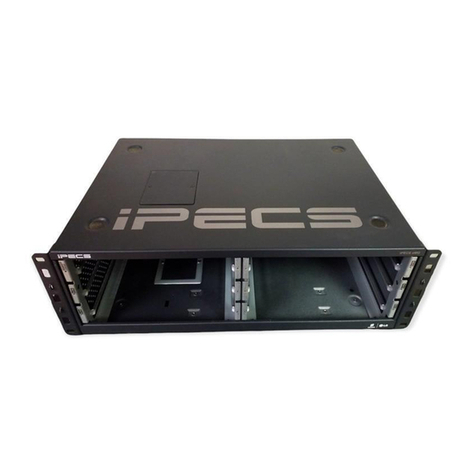
iPECS UCM User manual

iPECS UCM
Installation Manual
Please read this manual carefully before operating System.
Retain it for future reference.

iPECS UCM
Installation Manual Issue 1.1
Regulatory Information
Before making connections to the telephone network, you may be required to notify your local serving
telephone company of your intention to use "customer provided equipment.” You may further be required to
provide any or all of the following information:
PSTN Telephone numbers to be connected to the system.
Model name: iPECS UCM
Local regulatory agency registration number: locally provided
Ringer equivalence: 0.7B
Cable connector: Champ cable connectors (32 pairs)
This equipment complies with the following regulatory standards, that is, the safety requirements of EN60950-
1, and the EMC requirements of EN55032 and EN55024.
If the telephone company determines that customer provided equipment is faulty and may possibly cause
harm or interruption in service to the telephone network, it should be disconnected until repair can be affected.
If this is not done, the telephone company may temporarily disconnect service.
The local telephone company may make changes in its communications facilities or procedures. If these
changes could reasonably be expected to affect the use of the iPECS UCM or compatibility with the network,
the telephone company is required to give advanced written notice to the user, allowing the user to take
appropriate steps to maintain telephone service.
The iPECS UCM complies with rules regarding radiation and radio frequency emission as defined by local
regulatory agencies. In accordance with these agencies, you may be required to provide information such as
the following to the end user
European Union Declarations of Conformity
Ericsson-LG Enterprise Co.,Ltd. declare that the equipment specified in this document bearing the “CE”mark
conforms to the European Union Radio Equipment Directive(RED, 2014/53/EU), including the Electromagnetic
Compatibility Directive(EMCD,2014/30/EU) and Low Voltage Directive(LVD, 2014/35/EU). Copies of these
Declarations of Conformity (DoCs) can be obtained by contacting your local sales representative
FCC/CSA Interference Statement
This equipment has been tested and found to comply with the limits for a Class A digital device, pursuant to
part 15 of the FCC Rules. These limits are designed to provide reasonable protection against harmful
interference when the equipment is operated in a commercial environment. This equipment generates, uses,
and can radiate radio frequency energy and, if not installed and used in accordance with the instruction
manual, may cause harmful interference to radio communications. Operation of this equipment in a residential
area is likely to cause harmful interference in which case the user will be required to correct the interference at
their expense.
This device complies with part 15 /RSS-GEN of the FCC/IC rules. Operation is subject to the following two
conditions:
(1) This device may not cause harmful interference; and (2) This device must accept any interference received,
including interference that may cause undesired operation.
(1) l'appareil ne doit pas produire de brouillage, et (2) l'utilisateur de l'appareil doit accepter tout brouillage
radioélectrique subi, même si le brouillage est susceptible d'en compromettre le fonctionnement.

iPECS UCM
Installation Manual Issue 1.1
This Class A digital apparatus meets the requirements of the Canadian Interference-Causing Equipment
Regulations, CAN ICES-3(A)/NMB-3(A)
Cet appareil numérique de la classe A respecte toutes les exigences du Règlement sur le matériel brouilleur
du Canada.
The use of this device in a system operating either partially or completely outdoors may require the user to
obtain a license for the system according to the Canadian regulations. For further information, contact your
Local Industry Canada office.
Any changes or modifications in construction of this device that are not expressly approved by the party
responsible for compliance could void the user's authority to operate the equipment.
CAUTION
ATTENTION: Tout changement ou modification dans la construction de cet appareil qui ne sont pas
expressément approuvé par la partie responsable de la conformité pourraient annuler l'autorité de l'utilisateur
à utiliser l'équipement.
This is a class “A” product. In a domestic environment this product may cause radio interference in which case
the user may be required to take adequate measures.
WARNING
WARNING
This system employs a Lithium battery as back-up power for the real-time clock and memory. Risk of
Explosion if Battery is replaced by an Incorrect Type. Dispose of Used Batteries According to the
Instructions.
WARNING
This equipment generates and uses R.F. energy, and if not installed and used in accordance with the
Instruction Manual, it may cause interference to radio communications. It has been tested and found to
comply with the appropriate limits for a telecommunication device. The limits are designed to provide
reasonable protection against such interference, when operated in a commercial environment. Operation
of this equipment in a residential area could cause interference, in which case the user, at his own
expense, will be required to take whatever measures may be required to correct the interference.
- Disposal of a battery into fire or a hot oven, or mechanically crushing or cutting of a battery, that can
result in an explosion;
- Leaving a battery in an extremely high temperature surrounding environment that can result in an
explosion or the leakage of flammable liquid or gas;
- A battery subjected to extremely low air pressure that may result in an explosion or the leakage of
flammable liquid or gas.
- This system with a lithium battery must be operated below 2000m altitude.
Di spo sal of Old Appliance

iPECS UCM
Installation Manual Issue 1.1
When the displayed symbol (crossed-out wheeled bin) is adhered to a product, it designates the product is
covered by the European Directive 2012/19/EC.
All electric and electronic products should be disposed of only in special collection
facilities appointed by government or local/municipal authorities.
The correct disposal of your old appliance will help prevent potential negative
consequences for the environment and human health.
For more detail information about disposal of your old appliances, please contact
your city office, waste disposal service or the place of product purchase.

iPECS UCM
Installation Manual Issue 1.1
Revision History
ISSUE DATE DESCRIPTION OF CHANGES
1.0
2017/11/24
Initial Release
1.1 2019/03/11 SW version: 2.5.x.
- General Update
- S2K Shut down methods for operating OS programs
Copyright© 2017 Ericsson-LG Enterprise Co., Ltd. All Rights Reserved
This material is copyrighted by Ericsson-LG Enterprise Co. Ltd. Any unauthorized reproductions, use or
disclosure of this material, or any part thereof, is strictly prohibited and is a violation of Copyright Laws.
Ericsson-LG Enterprise reserves the right to make changes in specifications at any time without notice.
The information furnished by Ericsson-LG Enterprise in this material is believed to be accurate and reliable,
but is not warranted to be true in all cases.
Ericsson-LG Enterprise and iPECS are trademarks of Ericsson-LG Enterprise Co., Ltd.
The contents of this document are subject to revision without notice, due to continued progress in
methodology, design, and manufacturing. Ericsson-LG Enterprise shall have no liability for any error or
damage of any kind resulting from the use of this document.

iPECS UCM
Installation Manual Issue 1.1
I
Table of Contents
1INTRODUCTION...............................................................................................1
2General Description...........................................................................................2
2.1 iPECS UCMOverview........................................................................................................2
2.2 System Configurationand Components..........................................................................5
2.2.1 Call Server ......................................................................................................................6
2.2.1.1 UCM-S2K....................................................................................................................6
2.2.1.2 UCM-S960K/UCM-S60K/UCM-S30K/UCM-S10K/UCM-S4K........................................... 7
2.2.2 Media Gateway Modules Description.............................................................................8
2.2.2.1 UCM-ASLM................................................................................................................. 8
2.2.2.2 UCM-DSLM................................................................................................................. 9
2.2.2.3 UCM-MATM .............................................................................................................. 10
2.2.2.3.1 UCM-COIU ............................................................................................................11
2.2.2.3.2 UCM-EMIU ............................................................................................................11
2.2.2.3.3 UCM-LDIU.............................................................................................................11
2.2.2.4 UCM-MDTM2............................................................................................................ 12
2.2.2.5 UCM-MDTMX2................................................................................................
.......... 13
2.2.2.6 UCM-VPCM .............................................................................................................. 14
2.2.3 Cabinet..........................................................................................................................15
2.2.3.1 UCM-MGC3 (Media Gateway Cabinet)........................................................................ 15
2.2.3.1.1 UCM- LANU (LAN Unit) ..........................................................................................17
2.2.3.1.2 UCM-LCDU (LCD Unit)...........................................................................................18
2.2.3.1.3 UCM-PSUD (DC/DC Power Supply Unit) .................................................................19
2.2.3.2 UCM-1URMC (1U type Rack Mount Media Gateway Cabinet) ...................................... 20
2.2.4 iPECS UCM IP Phone & Digital Phone ........................................................................21
2.3 System Characteristics.....................................................................................................23
2.3.1 Maximum Capacity.......................................................................................................23
2.3.2 Dimension and Weight..................................................................................................23
2.3.3 Environment Specifications ..........................................................................................23
2.3.4 Power Specifications.....................................................................................................24
2.3.5 CO LOOP Specification................................................................................................24
3General Installation Procedure......................................................................25
3.1 Installationand SafetyPrecautions................................................................................25
3.2 Unpacki ng...........................................................................................................................26
3.3 Cabinet Installation............................................................................................................27
3.3.1 UCM-MGC3 Installation................................................................................................27
3.3.1.1 Closing and Opening the front cover ........................................................................... 27
3.3.1.2 Installing Single and Multiple cabinet-Floor mount & Rack mount .................................. 29
3.3.1.3 UCM Synchronization ................................................................................................32
3.3.1.4 UCM-MGC3 Grounding.............................................................................................. 35
3.3.1.5 UCM-PSUD installation for UCM-MGC3...................................................................... 38
3.3.1.5.1 PSUD Installation...................................................................................................38
3.3.1.5.2 Rectifier Installation Requirements ..........................................................................40
3.3.1.5.3 UCM-PSUD Power Cable Connection .....................................................................41
3.3.1.5.4 Rectifier Cable Connection .....................................................................................42

iPECS UCM
Installation Manual Issue 1.1
II
3.3.2 UCM-1URMC Installation .............................................................................................45
3.3.2.1 Installing Floor mount & Rack mount ........................................................................... 45
3.3.2.2 UCM-1URMC Grounding............................................................................................ 46
3.3.2.3 UCM-1URMC Power Cable Connection ...................................................................... 47
3.4 Call Server Installation......................................................................................................48
3.4.1 UCM-S2K Installation....................................................................................................48
3.4.2 UCM-S30K/S2K Redundancy Connection...................................................................53
3.5 Gateway Module Installation ...........................................................................................55
3.5.1 Gateway Module Insertion and Removal .....................................................................55
3.5.2 UCM-ASLM Installation.................................................................................................56
3.5.3 UCM-DSLM Installation ................................................................................................58
3.5.4 UCM-MATM Installation................................................................................................60
3.5.5 UCM-MDTM2 Installation .............................................................................................65
3.5.6 UCM-MDTMX2 Installation...........................................................................................68
3.5.7 UCM-VPCM Installation................................................................................................72
3.6 Cable Installation...............................................................................................................73
3.6.1 Trunk/Extension Champ Connector Cable Connection...............................................73
3.6.2 LAN Cable Connection .................................................................................................74
3.6.3 LAN Wiring Structure....................................................................................................75
3.6.4 RS-232 Connections.....................................................................................................75
3.7 Checklist after System Power On...................................................................................76
4Appendix A. Open Source Software.............................................................. 80
5Appendix B. Power Consumption Calculation.............................................. 82

iPECS UCM
Installation Manual Issue 1.1
1
1 INTRODUCTION
This Installation Manual provides the information required for installation, operation and maintenance of the
Ericsson-LG Enterprise iPECS UCM (Unified Communication Manager) system.
For system feature and programming, refer to the iPECS UCM F&O (Feature and Operation) and WMS
Manual provided separately.

iPECS UCM
Installation Manual Issue 1.1
2
2 General Description
This chapter shows the brief description of iPECS UCM, Gateway Modules and Cabinets.
2.1 iPECS UCM Overview
The iPECS UCM is Ericsson-LG Enterprise’s Internet Protocol (IP) Enterprise Communications Solution
designed to meet the telecommunication needs of the large sized business. iPECS UCM uses advanced
packet voice and IP switching technology, which is combined with a rich feature content, to set a new standard
in Voice over IP (VoIP) systems.
The iPECS UCM consists of a family of intelligent Gateway Modules, media gateway cabinets and Call Server,
which are interconnected over Ethernet LAN, easing the installation process. A variety of Gateway Modules
are available including analog and digital network access gateways, which connect to the Public Switched
Telephone Network (PSTN), Integrated Services Digital Network (ISDN) or public and private VoIP networks.
The Gateway Modules, which make up the iPECS UCM, can be installed in a Media Gateway Cabinet (1U or
7U type). The cabinet can be on floor or 19” rack, as best fits the user needs and equipment room.
The iPECS UCM supports a variety of Phones; LIP phones, standard VoIP phones (SIP), WLAN Phone,
analogue SLT and various of soft clients including Phontage, UCS client and Mobile Client. With the LIP
Phones, commonly used features are activated by selection of a single button. Additionally, most functions can
be accessed from any telephone by dialing specific codes. For LIP users, these “dial codes” may be assigned
to Flexible buttons for easy access. In addition to the LIP Phones, optional LIP DSS Consoles are available to
expand the number of Flexible buttons available to the user.
The iPECS UCM provides an environment rich in features beyond today’s traditional circuit switched
telephone systems. In addition to a fully featured voice intercom, iPECS UCM incorporates basic Auto
Attendant/Voice Mail, Least Cost Routing, Automatic Call Distribution, and VoIP network interface, as well as
Web Management System. iPECS UCM incorporates an interface to the iPECS UCM Applications Service
Provider, a TAPI 3.1 TSP/MSP, TR-87, SNMP, CSTA and Ericsson-LG Enterprise propriety interface (UCTI,
SAPP). Unified Communications Services (UCS), iPECS Attendant is supported through optional application
software providing enhanced communications and presence. An optional Network Management Server (UCM-
NMS) software package is available allowing monitoring and management of environments.
The reliability, extensive feature content, the ability to support present and future applications with iPECS
UCM Call Server and the capability to use an array of Gateway Modules and instruments, permit iPECS UCM
to be tailored to meet the short and long term needs of the most demanding customer requirements.

iPECS UCM
Installation Manual Issue 1.1
3
Figure 2-1 shows the iPECS UCM configuration. It is a diagram of the various Gateway Modules, terminals
and applications available with iPECS UCM.
Figure 2-1 iPECS UCM configuration

iPECS UCM
Installation Manual Issue 1.1
4
Figure 2-2 shows the iPECS UCM Systems configuration at the 19” Rack Mount
Figure 2-2 iPECS UCM Systems 19” Rack Mount Configuration

iPECS UCM
Installation Manual Issue 1.1
5
2.2 System Configuration and Components
Category Name Description
Call Server
UCM-S2K 2,000 Ports Embedded Gateway Module Type Server.
UCM-S4K 4,000 ports Commodity Server.
UCM-S10K
10,000 ports Commodity Server.
UCM-S30K 30,000 ports Commodity Server.
UCM-S60K 60,000 ports Commodity Server
UCM-S120K
120,000 ports Commodity Server only in ACT-ACT
UCM-S240K 240,000 ports Commodity Server only in ACT-ACT
UCM-S480K 480,000 ports Commodity Server only in ACT-ACT
UCM-S960K 960,000 ports Commodity Server only in ACT-ACT
Gateway
Module
UCM-ASLM Analog Subscriber Line Gateway Module.
UCM-DSLM Digital Subscriber Line Gateway Module.
UCM-MATM
Multi-function Analog Trunk Gateway Module
UCM-MATM
option Unit
UCM-COIU Central Office Interface Unit.
UCM-EMIU Ear and Mouth Interface Unit.
UCM-LDIU
Loop Dial Interface Unit.
UCM-MDTM2 Multi-function Digital Trunk Gateway Module.
UCM-MDTMX2 Multi-function Digital Trunk Gateway Module. 2 Link
UCM-VPCM Voice Prompt and Conference Gateway Module.
Cabinet UCM-MGC3 Media Gateway Cabinet on 7U type Rack Mount
POWER UCM-PSUD DC/DC Power Supply Unit
UCM-1URMC
Media Gateway Cabinet on 1U type Rack Mount
UCM-S120K/UCM-S240K/UCM-S480K/UCM-S960K licenses are only used in the ACT-ACT mode.
Note)

iPECS UCM
Installation Manual Issue 1.1
6
2.2.1 Call Server
The iPECS UCM has 2 types of server, embedded Gateway Module type and commodity type. The embedded
Gateway Module type servers are UCM-S2K. The commodity servers are UCM-S4K, UCM-S10K and UCM-
S30K and UCM-S60K in the ACT-STB mode.
In the ACT-ACT mode, the commodity servers are UCM-S4K, UCM-S10K, UCM-S30K, UCM-S60K, UCM-
S120K. UCM-S240K, UCM-S480K, and UCM-960K.
2.2.1.1 UCM-S2K
The UCM-S2K (2,000 Ports Embedded Gateway Module Type Server) is equipped with an embedded CPU
Gateway Module and can accommodate up to 2,000 ports. It supports max. 4GB DDR3 memory, SATA2
128GB SSD, 2 USB ports supporting USB 2.0, 10/100/1000Mbps Ethernet 2 ports and VGA (Video Graphics
Array) port.
CPU
Specifications
Intel CPU ATOM N2800 1.8GHz
Memory
DRAM: SO-DIMM DDR3 4GB
SSD 128GB
Network interface
10/100/1000Mbps Ethernet 2 ports
USB 2.0 x 2 ports
VGA 1 port
Others
Coin Battery: 3V(CR2032)
Reset switch
Status LED
Mechanical specification
Gateway Module dimension (W x L): 255 mm x 334.5 mm (Including card edge)
Gateway Module weight: 970g
Figure 2-3 UCM-S2K

iPECS UCM
Installation Manual Issue 1.1
7
2.2.1.2 UCM-S960K/UCM-S60K/UCM-S30K/UCM-S10K/UCM-S4K
The UCM-S960K, UCM-60K, UCM-S30K, UCM-S10K and UCM-S4K are commodity servers whose
specifications should be better than the following examples.
UCM Server Minimum Requirements
UCM-S960K UCM-S60K UCM-S30K UCM-S10K UCM-S4K
Max. Ports 960,000 60,000 30,000 10,000 4,000
CPU Intel Xeon
E5-2637 Intel Xeon
E5-2637 Intel Xeon
E3-1220
Intel Xeon
E5-2690
Intel Xeon
E5-2609
CPU CORE 8 4 2
CPU CLOCK 3.5 GHz 3.1 GHz 2.93 GHz 2.5 GHz
RAM 8 GB 4 GB
HDD 1 TB 300 GB
Ethernet 2 Ports (10/100/1000Mbps)

iPECS UCM
Installation Manual Issue 1.1
8
2.2.2 Media Gateway Modules Description
The iPECS UCM is consist of 6 media gateway Modules, which are mounted in UCM-MGC3 or UCM-1URMC.
UCM-ASLM (Analog Subscriber Line Gateway Module)
UCM-DSLM (Digital Subscriber Line Gateway Module)
UCM-MATM (Multi-function Digital Trunk Gateway Module)
UCM-MDTM2 (Multi-function Digital Trunk Gateway Module)
UCM-MDTMX2 (Multi-function Digital Trunk Gateway Module 2 Links)
UCM-VPCM (Voice Prompt and Conference Gateway Module)
2.2.2.1 UCM-ASLM
The UCM-ASLM (Analog Subscriber Line Gateway Module) provides analog interfaces between SLTs (Single
Line Telephones) and iPECS UCM System. It consists of 32 SLT line interface circuits and a LAN interface
circuit.
It supports -48V DC power feed, ring signal supply, CID (Caller ID) transmission and DTMF dial signal
detection for SLTs. The UCM- ASLM Gateway Module supports message waiting signal generation and 5 REN
(Ringer Equivalence Number).
Maximum SLT installation distance is 8Km (26,000 feet) in case of using AWG24 or UTP5 cable.
Maximum capacity (Voice data length per packet)
Specifications
G.711: 32 Channels
Interface specification
10/100Base-T Ethernet 1port
SIO 1 port
Others
Status LED
Channel LED
Reset switch
Electrical specification
Supply Power Input: -48V, +5V, DGND, FGND
Mechanical specification
Gateway Module dimension (W x L): 255 mm x 334.5 mm (Including card edge)
Figure 2-4 UCM-ASLM

iPECS UCM
Installation Manual Issue 1.1
9
2.2.2.2 UCM-DSLM
The UCM-DSLM (Digital Subscriber Line Gateway Module) provides digital interfaces between DKTs (Digital
Key Telephones) and iPECS UCM System. It consists of 32 DKTs interface circuits and a LAN interface circuit.
It supports LDP-61xx series and LDP-9130D.
Maximum capacity (Voice data length per packet)
Specifications
G.711: 32 Channels
Maximum installation distance
1Km(AWG 22 ~ 24 or UTP 5 Cable)
DKTs Feeding Voltage
DC -48V
Interface specification
10/100 Base-T Ethernet 1port
SIO 1 port
Others
Status LED
Channel LED
Reset switch
Electrical specification
Supply Power Input: -48V, +5V, DGND, FGND
Mechanical specification
Gateway Module dimension (W x L): 255 mm x 334.5 mm (Including card edge)
Gateway Module weight: 667g
Figure 2-5 UCM-DSLM

iPECS UCM
Installation Manual Issue 1.1
10
2.2.2.3 UCM-MATM
UCM-MATM (Multi-function Analog Trunk Gateway Module) supports CO/LD/EM analog trunk interface and
provides Packet to PCM and PCM to Packet conversion for voice communication in the IP network.
Option Modules (UCM-COIU, UCM-LDIU, UCM-EMIU) are used for analog trunk interface.
Trunk capacity (Max. 16 ports)
Specifications
Trunk Type Max. Port
CO/ LD/RD 16 port
2-wire E&M
16 port
4-wire E&M 8 port
Analog trunk type and option Module
Trunk Type Option Module
CO UCM-COIU (Central Office Interface Unit)
LD UCM-LDIU (Loop Dial Interface Unit)
E&M UCM-EMIU (E&M Interface Unit)
* Each option Module provides 4 ports (except 4-wire E&M providing 2 ports) and 3 option Modules can be
mounted in the UCM-MATM Gateway Module.
Different types of option Modules can be used simultaneously.
Interface specification
10/100Base-T Ethernet 1port
SIO 1 port
Others
Status LED
Channel LED
Reset switch
Electrical specification
Input power: -48V, +5V, DGND, FGND
Mechanical specification
Gateway Module dimension (W x L): 255 mm x 334.5 mm (Including card edge)
Gateway Module weight: 940g
Figure 2-6 UCM-MATM

iPECS UCM
Installation Manual Issue 1.1
11
2.2.2.3.1 UCM-COIU
The UCM-COIU (Central Office Interface Unit) is the option Module for CO interface and performs the
hardware functions as follows:
Loop seizure
Ring detection
Polarity-reverse detection
Pulse dialing
2.2.2.3.2 UCM-EMIU
The UCM-EMIU (Ear & Mouth Interface Unit) is the option module for E&M interface and performs the
hardware functions listed as below:
E&M Type: Type V only supported (using two lines for supervisor signaling: E, M)
E line: Detect the off-hook condition of the other party (supplying DC -48V)
M line: Connected to the ground in order to indicate the off-hook condition or opened to inform the on-
hook condition.
2-wire E&M: Voice TIP, voice RING, E, M
4-wire E&M: voice TX_TIP, voice TX_RING, voice RX_TIP, voice RX_RING, E, M
2.2.2.3.3 UCM-LDIU
The UCM-LDIU (Loop Dial Interface Unit) is the option Module for LD interface and performs the hardware
functions as below:
Voice signal loop
Loop seizure
Pulse dialing
Polarity-reverse sending
Polarity-reverse detection

iPECS UCM
Installation Manual Issue 1.1
12
2.2.2.4 UCM-MDTM2
The UCM-MDTM2 (Multifunction Digital Trunk Gateway Module) supports one digital trunk
It provides digital trunk (E1/T1, 2048K/1544K bps ISDN PRI, CCS No.7) and it is available selectively with
switch or Gateway Module initialization information.
For trunk line interface,
E1 Cable line impedance matching jumper should be set to 120Ω.
T1 Cable line impedance matching jumper should be set to 100Ω.
UCM-MDTM2 can match the frequency synchronization over the network system through LANU after
extracting the clock from a particular trunk.
Channel capacity
Specifications
2,048Kbps E1 Trunk / ISDN PRI European mode: 32 Ch. (30B+1D)
1,544Kbps T1 Trunk / ISDN PRI American mode: 24 Ch. (23B+1D)
Line characteristics(E1 / T1)
E1 ( ITU-T G.703 and G.704)
Transfer rate: 2.048Mbps +/- 50ppm
Impedance: 120 ohm
Line code: HDB3
T1 ( ITU-T G.703 and G.704)
Transfer rate: 1.544Mbps +/- 50ppm
Impedance: 100 ohm
Line code: AMI / B8ZS
Interface specification
Digital line interface: E1 / T1 / PRI / No.7
10/100Base-T Ethernet 1 port
SIO 1 port
Others
Status LED
Channel LED
Reset switch
Electrical specification
Input power: +5V, DGND, FGND
Mechanical specification
Gateway Module dimension (W x L): 255 mm x 334.5 mm (Including card edge)
Gateway Module weight: 540g
Figure 2-7 UCM-MDTM2

iPECS UCM
Installation Manual Issue 1.1
13
2.2.2.5 UCM-MDTMX2
The UCM-MDTMX2 (Multifunction Digital Trunk Module, 2 Link) supports two digital trunks. It provides digital
trunk (E1 / T1, 2048K / 1544K bps ISDN PRI, CCS No.7) interworking function in iPECS UCM system, and
you can choose the way by the trunk switch configuration and module initialization information.
Line impedance of digital trunks are set automatically when you selected E1 / T1 mode. See below impedance.
Two digital trunk lines connected to the digital trunk MDTMX2 must be in the same manner provided by the
same operator. If you do not use the same way or if it is not the same operators must be configured separately
using the MDTM2.
Digital trunk capacity 2Link
Specifications
Two digital trunks are only supported with the same network synchronization
2,048Kbps E1 Trunk / ISDN PRI European mode: 32 Ch. (30B+1D)
1,544Kbps T1 Trunk / ISDN PRI American mode: 24 Ch. (23B+1D
Line characteristics(E1 / T1)
E1 ( ITU-T G.703 and G.704)
- Transfer rate: 2.048Mbps +/- 50ppm
- Impedance: 120 ohm
- Line code: HDB3
T1 ( ITU-T G.703 and G.704)
- Transfer rate: 1.544Mbps +/- 50ppm
- Impedance: 100 ohm
- Line code: AMI / B8ZS
Interface specification
Digital line interface: E1 / T1 / PRI / No.7
10/100Base-T Ethernet 1port
SIO 1 port
Others
Status LED
Dip Switch for setting Mode
Channel LED
Reset switch
Electrical specification
Input power: +5V, DGND, FGND
Mechanical specification
Gateway Module dimension (W x L): 255 mm x 334.5 mm (Including card edge)
Gateway Module weight: 495g
Figure 2-8 UCM-MDTMX2
Table of contents
Other iPECS Conference System manuals
Popular Conference System manuals by other brands

Cisco
Cisco EX60 user guide

Nomura Engineering
Nomura Engineering TS01 E 8sw manual

Kingfisher
Kingfisher KI 025 Series OPERATING & MAINTENANCE GUIDE

Crestron
Crestron UC-MX50-Z-UPGRD quick start

Graco
Graco ProMix Auto Software instructions

Danish Interpretation Systems
Danish Interpretation Systems DCS 6000 user manual