IPS CR 25 A User manual

01.05/WE
CR 25 A
Handgerät zum Umreifen mit Stahlband
Hand tool for steel strapping
Appareil pour le cerclage par feuillard d'acier
Apparecchio per reggiare con reggetta d'acciaio
Ab Serie-Nr. 2500
From serie no 2500
A partir du no de série 2500
A partire dal no. di serie 2500
ORGAPACK
BETRIEBSANLEITUNG UND SICHERHEITSVORSCHRIFTENBETRIEBSANLEITUNG UND SICHERHEITSVORSCHRIFTEN
BETRIEBSANLEITUNG UND SICHERHEITSVORSCHRIFTEN
OPERAOPERA
OPERAOPERA
OPERATINGTING
TINGTING
TING AND SAFETY INSTRAND SAFETY INSTR
AND SAFETY INSTRAND SAFETY INSTR
AND SAFETY INSTRUCTIONSUCTIONS
UCTIONSUCTIONS
UCTIONS
MODE D‘EMPLOI ET DE SÉCURITÉMODE D‘EMPLOI ET DE SÉCURITÉ
MODE D‘EMPLOI ET DE SÉCURITÉ
ISTRUZIONI PER L‘USO E DI SICUREZZAISTRUZIONI PER L‘USO E DI SICUREZZA
ISTRUZIONI PER L‘USO E DI SICUREZZA
DEUTSCH 3
ENGLISH 17
FRANÇAIS 31
ITALIANO 45

01.05/WE 17
ORGAPACK CR 25 A
1TECHNICAL DATA
TABLE OF CONTENTS
Weight 3.2 kg (7 lbs)
Dimensions Length 302 mm (17.75")
Width 130 mm (5")
Height 180 mm (7")
Tensionforce Up to approx. 3000 N
Tensionspeed 75 mm/s (3“/s)
Air pressure Maximum 6 bar static
Air consumption
– Tensioning 4 Nl/s
– Sealing 3.4 Nl
Air connection G 1/4“ ( 1/4“ NPT)
Sealing Sealjoint with 1 notch
Emission sound pressure
levels,measurement
type A (EN ISO 11202) LpA 83 dB (A)
Vibrations at handle
(EN ISO 8662-1) ah,w < 2,5 ms-2
STEELSTRAP
Strap width 13, 16, 19 mm
(1/2", 5/8", 3/4")
Normalquality:
Strap thickness 0.40–0.63mm (.015"–.024")
Tensilestrength Up to approx. 850 N/mm2
(117'000lbs/in2)
Highstrength
quality:
Strap thickness 0.40–0.63mm (.015"–.024")
Tensilestrength Up to approx. 1100 N/mm2
(156'000lbs/in2)
SEALS
Strap width 13 mm CSP 411
Strap width 16 mm CSP 511
Strap width 19 mm CSP 611
Page
1 Technical data 17
2 General information 18
2.1 Information on environmental protection 18
3 Safetyinstructions 19
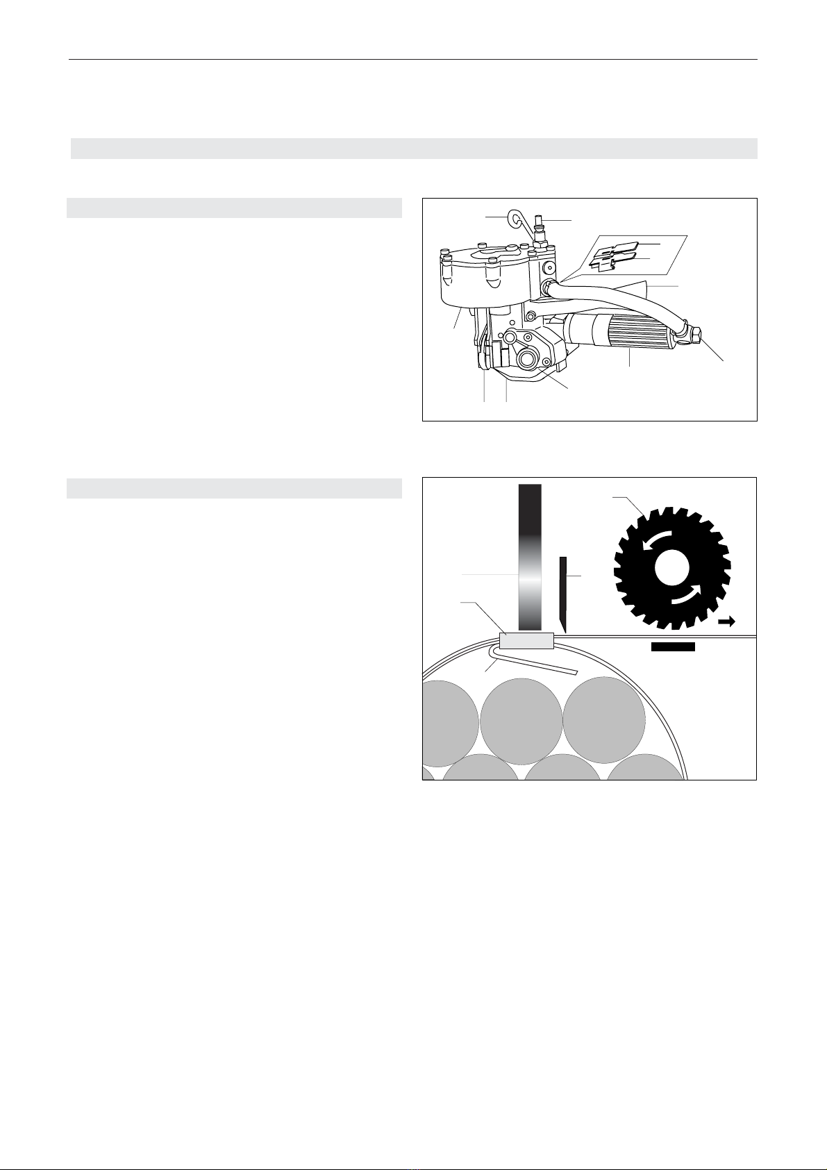
4 Description 20
4.1 Design 20
4.2 Function 20
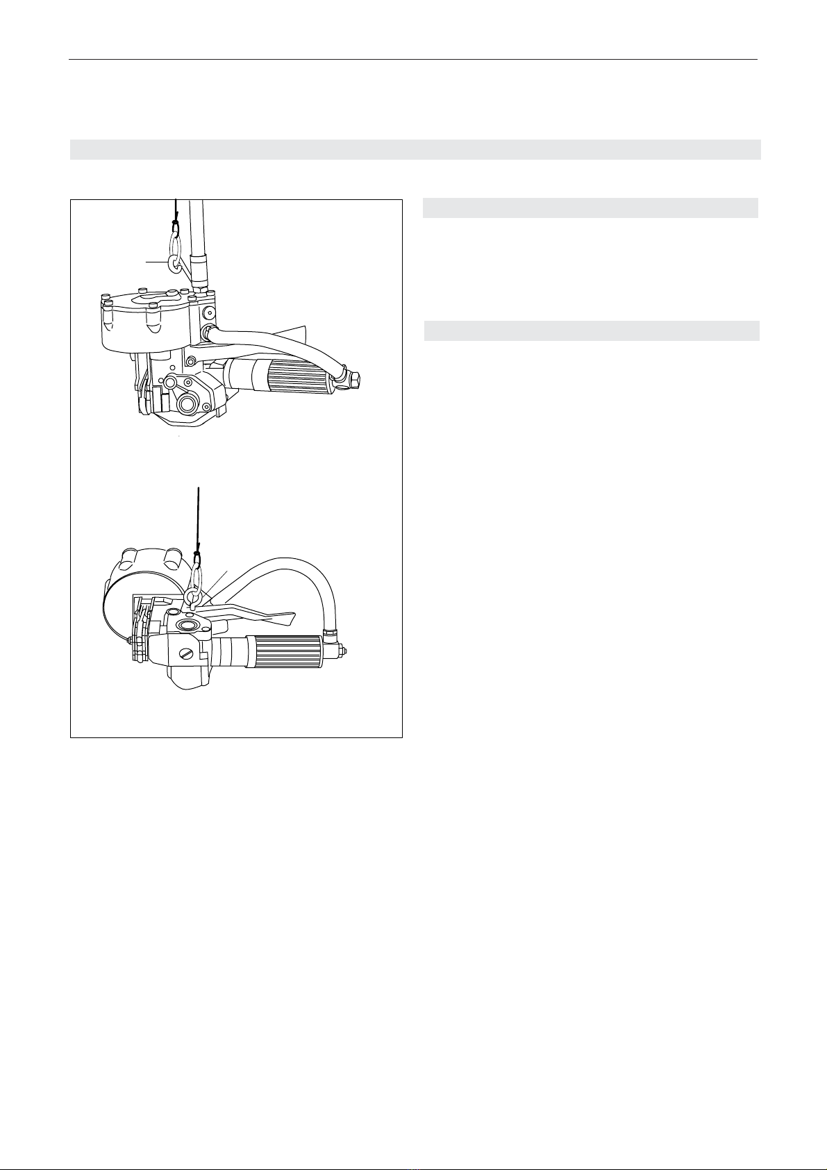
5 Initial operation 21
5.1 Suspending the tool 21
5.2 Compressed-air connection 21
6 Operatinginstructions 22
6.1 Operating the tool 22
7 Preventive and corrective maintenance 24
7.1 Adjustingtensioning force/tensioning speed 24
7.2 Setting clearance between tension wheel and
tension plug 24
7.3 Replacingtension wheel 24
7.4 Replacing cutting knife 25
7.5 Replacing jaws and notcher 25
7.6 Cleaning the tool 25
8 Partslist 26
Explosiondrawing 28
9 Parts list compressed air motor 29
Explosiondrawing 30
We take sole responsibility for declaring that the
tool CR 25 A, to which this declaration refers, is in
full compliance with the current requirements of the
guidelines laid down by the council on 22th June
1998(98/37/EEC), “Machine Guidelines“.
According to norm:
EN 292-1, EN 292-2, EN 349, EN 983, EN 1050
prEN792-2
CH-8953Dietikon, February 2002
Manager Manager
Sales & Marketing: Engineering:
R.Kieffer M. Binder
DECLARATION OF AGREEMENT

18 01.05/WE
ORGAPACK CR 25 A
CAUTION!
Used where there is
danger to life and health.
WARNING!
Used for danger which
can cause material
damage.
NOTE!
Used for general infor-
mation and information
which if not followed can
cause faults in the
operating sequence.
2GENERAL INFORMATION
These operating instructions are intended to simplify
familiarisation with the strapping tool and the possibili-
ties of application for the intended purpose. The oper-
ating instructions contain important information con-
cerning the safe, proper and efficient use of the strap-
ping tool. Observation of the information will help to
avoid danger, reduce repairs and stoppages and in-
crease the reliability and service life of the strapping
tool.
The operating instructions must always be available at
the place of operation of the strapping tool. They must
be read and observed by all persons concerned with
work on the strapping tool. This work specifically
includes operation, refilling of operating material, fault
elimination and maintenance.
In addition to the operating instructions and the regu-
lations for accident prevention effective in the country of
use and place of application, the recognised technical
regulations for safety and proper working must also be
observed.
2.1 INFORMATION ON ENVIRONMENTAL
PROTECTION
This tool is manufactured without any physical or
chemical substances which could be dangerous to
health. For disposal of all the parts, the governmental
instructions must be observed.

01.05/WE 19
ORGAPACK CR 25 A
Use for the intended purpose
The tool is intended for strapping round packages,
bundles of sectional steel, pipes etc.
This tool was designed and manufactured for safe
handling during the strapping operation.
The tool processes steel straps only.
Possible misuse
The use of plastic straps is not possible.
3SAFETY INSTRUCTIONS
Inform yourself!
Read the operating
instructions carefully.
Protect yourself!
When operating the tool,
wear eye, face and hand
protection (cut-proof
gloves).
Warning:
Strap will snap forward!
When cutting the strap,
hold the upper portion and
stand safely away from
the strap.
Caution:
The lower strap will snap
forward.
Warning:
Strap could break!
Do not stand in line with
the strap while it is
tensioned. The strap
couldbreak!
Caution:
Danger of squeezing!
Do not put your fingers
into the tension wheel
area.
Caution:
Only strap packed
goods!
Do not put hands or other
parts of the body bet-
ween the strap and the
package during the strap-
ping process.
Do not exceed the air
pressure!
Do not exceed the recom-
mendedair pressure
Use safety coupling!
For connecting the air
hose to the tool, use only
a safety coupling
Do not use a bottled
air or gas source!
Do not operate tis tool by
usining a bottled air or
gas source
Caution:
If work is carried out
using a spring balancer,
only a spring balancer
that complies with the
safety regulations may
be used.
OriginalORGAPACK
seals must be used
exclusively.
Original ORGAPACK
spare parts must be
used exclusively!
Not using original spare
parts will dissolve the
warranty and the liability.
jklsfjklsdj
lksdfjkl
jkljsdllkjjkljsd
fkljjklkjkljsdafj
asdfjklkjjkljklj
ksldafkjkljkl
jkljklkljsdafjlkj
jkljjkljklkljljlk
max.6 bar
0
2
46810
12
14
16
ORGAPACK
Original
ORGAPACK
Original

20 01.05/WE
ORGAPACK CR 25 A
4DESCRIPTION
4.2 FUNCTION
– Feed the strap manually through the seal (2/1).
– Bend the strap start (2/5).
– Tensioning by feed wheel principle (2/4).
– Sealing by notching (2/2) the seal.
– Strap cut with knife (2/3)
4.1 DESIGN
1 Compressed air connection
2 Yellow button (Sealing)
3 Green button (Tensioning)
4 Handle
5 Pressure reduzing valve
6 Compressed air motor
7 Tension wheel and tension plug
8 Base plate
9 Sealing jaws
10 Compressed air cylinder
11 Suspension bow
Fig. 1
Fig. 2
4
1
3
2
5
5
1
4
6
7
8
9
11
2
3
10

01.05/WE 21
ORGAPACK CR 25 A
5INITIAL OPERATION
5.1 SUSPENDING THE TOOL
If the tool is equipped with a suspension bow (3/1) it
can be suspended on a spring balancer. By mounting
an M6-eye bolt (3/2) it is possible to perform horizontal
strapping.
5.2 COMPRESSED-AIR CONNECTION
Motor and sealing piston are lubricated by oil mist of
the compressed air. Properly prepared compressed
air is therefore essential for trouble-free operation of
the tool. This can only be ensured by a reliably
functioning maintenance unit, consisting of water
separator, pressure reducing valve with pressure
gauge and oil mist lubricator.
The oil mist lubricator should supply sufficient oil. The
length of the hose between the CR 25 A and the main-
tenance unit should not exceed 5 m (15 ft). The
internal diameter of the pipe should be at least 10 mm
(3/8“). It must be ensured that the hose does not form
loops, where oil can collect.
Fig. 3
1
2

22 01.05/WE
ORGAPACK CR 25 A
6.1OPERATINGTHE TOOL
– Draw the strap from the dispenser, slide the strap
through the seal (4/1) and wind strap around the
package.
– Push the strap start a second time through the seal.
– Bend the strap start (5/1) below the seal 3–4 cm
(1–2“).
– Pull the strap tightly by hand and take a portion of
the strap leading to the dispenser with the left hand
approx. 20 cm (8“) away from the seal.
– Hold the handle (6/1) of the tool in the right hand
and raise the motor up to the stop.
– Insert the strap below the tension wheel completely
into strap guide. At the same time push the tool
forward against the seal.
– Release the motor.
6OPERATING INSTUCTIONS
Fig. 4
Fig. 5
1
1
Fig. 6
1

01.05/WE 23
ORGAPACK CR 25 A
Tensioning
– Press the green button completely down with the
thumb of the right hand. Release green button. The
strap is tensioned until the air motor stops.
The tensioning force can be infinitely
adjusted (see chapter 7.1).
Interrupting the tensioning process
– Press catch (7/2) to the left, green button rises and
tensioning is interrupted.
If the items to be strapped are mainly
delicate products, it is recommended to
remove the catch. The green button will then no
longer be locked when pressed down.
Sealing
– Press the yellow button (8/1) with the right thumb
until the seal is notched and the strap is cut off.
– Raise the motor to the stop and swivel the tool
away from the strapping to the right at the rear.
Check of seal
To obtain the maximum seal efficiency, the notches
have to be cut properly into the seal. If these notches
are not correctly cut, replace jaws and notcher (see
Chapter 7.5).
Fig. 7
Fig. 8
1
2
1

24 01.05/WE
ORGAPACK CR 25 A
7.1 ADJUSTING TENSIONING FORCE/
TENSIONING SPEED
– Set air pressure at pressure reducing valve of
maintenance unit to 4–6 bar.
– With a screwdriver adjust pressure reducing valve
(9/1) of air motor, so that the motor stops when the
required tension is reached. It should be ensured
that the seal is notched properly and that the strap
is cut off.
7.2 SETTING CLEARENCE BETWEEN TENSION
WHEEL AND TENSION PLUG
The tension wheel and the tension plug must
not touch (damage the teeth). If the spacing
is too great, the strap slips through before the final
tension is reached.
– Disconnect tool from air supply.
– Loosen set screw (10/1).
– Set tension plug (10/2) with screwdriver, so that the
clearence between tension wheel and tension plug
is 0.1–0.25 mm (.0039“–.0098“). Turning clockwise
decreases the clearence, turning counterclockwise
increases the clearence.
– Turn tension plug so that a notch of the tension plug
points in the direction of the set screw (10/1).
– Tighten set screw (10/1).
– Check clearence, reset if necessary.
7.3 REPLACING TENSION WHEEL
If the tension wheel spins before the required
strap tension is reached, the tension wheel
must be replaced (precondition: clearence set correctly,
see chapter 7.2).
Removal
– Disconnect tool from air supply.
– Remove two cylinder screws (11/1).
– Carefully remove cover (11/2) from tension shaft.
– Removecounter washer (11/3), thrust bearing (11/4)
and tension wheel (11/5). Replace tension wheel.
Installation
– Install the parts in reverse order.
– The 45°-chamfer of the tension wheel must be out-
side.
– Secure cylinder screws (11/1) with Loctite 243.
– Set clearence between tension wheel and tension
plug (see chapter 7.2).
7PREVENTIVE AND CORRECTIVE MAINTENANCE
Fig. 11
Fig. 10
Fig. 9
1
1
2
0,1–0,25 mm
1
2
4
5
3

01.05/WE 25
ORGAPACK CR 25 A
7.4 REPLACING CUTTING KNIFE
Removal
– Remove tension wheel (see chapter 7.3).
– Remove gear housing (12/9) including air motor
and shaft.
– With screwdriver loosen special screw (12/1).
– Remove shaft (12/2) and compression spring (12/3).
– Remove base plate (12/4).
– Remove cylinder screw (12/6).
– Remove cutter guide (12/5), remove and replace
cutting knife (12/8). Observe position of spring
(12/7).
Installation
– Install the parts in reverse order.
– Secure cylinder screw (12/6) and special screw
(12/1) with Loctite 243.
– After installation of gear housing (12/9) hang up
compression spring (12/3) with screwdriver.
7.5 REPLACING JAWS AND NOTCHER
Removal
– Connect the tool to the air supply, depress yellow
button (13/1) and hold it in position.
– Disconnect the tool from air supply and release
yellow button.
– Remove two special screws (13/6).
– Take down jaw unit.
– Remove lock nut (13/5).
– Remove front plate (13/4), remove and replace
notcher (13/3) and jaws (13/2).
Installation
– Install the parts in reverse order.
– Secure special screws (13/6) with Loctite 243.
7.6 CLEANING THE TOOL
– The tool should be regulary cleaned. Especially the
tension wheel and the jaw unit should be kept
clean. The easiest way to do this, is to use com-
pressed air and to blow out the dust (wear eye
protection).
Fig. 12
7
5
3
4
6
8
9
1
2
1
2
3
4
5
6
Fig. 13

26 01.05/WE
ORGAPACK CR 25 A
1 1174.200.115 Cylinder 1
2
3
4
5 1174.200.114 Cylinder cover 1
6
7
8 1820.100.036 Valve stem, long 1
9 1820.100.030 Sleeve 2
10 1820.100.033 Ring 1
11 1820.100.034 Sleeve 1
12 1927.601.020 O-Ring, ø 10 x 2 4
13 1927.601.600 O-Ring, ø 16.1 6
14 1820.010.208 Compression spring 1
15
16 1820.100.035 Valve stem, short 1
17 1820.100.031 Sleeve 1
18 1820.100.032 Sleeve 1
19 1925.010.802 Ball 1
20 1820.010.047 Compression spring conical 1
21 1927.600.420 O-Ring, ø 4 x 2 1
22
23 1174.200.120 Piston 1
24 1928.011.050 Piston ring, ø 105 1
25 1927.600.610 O-Ring, ø 6 x 1,5 1
26 1820.020.261 Washer 2
27 1916.306.062 Lock washer, M 6 1
28 1927.601.010 O-Ring, ø 10 x 1,5 1
29 1174.200.137 Gasket 1
30
31
32 1174.200.131 Slider 1
33 1820.030.413 Bolt 1
34 1174.200.128 Link 2
35
*36 1174.200.141 Jaw 13 mm 2
*36 1174.200.142 Jaw 16 mm 2
*36 1174.200.143 Jaw 19 mm 2
37
38 1174.200.125 Notcher 13 mm 2
38 1174.200.126 Notcher 16 mm 2
38 1174.200.127 Notcher 19 mm 2
39
40 1174.200.132 Plate 1
41 1174.200.133 Front plate 13 mm 1
41 1174.200.134 Front plate 16 mm 1
41 1174.200.135 Front plate 19 mm 1
42
43
44 1820.020.262 Bushing 1
45 1820.020.263 Bushing 2
When ordering please indicate part number and quantity Explosion drawing see page 28
*Recommended spare parts
Pos. Part no Part name Quantity
8PARTS LIST 1174.200.100/11
Pos. Part no Part name Quantity
46 1820.030.415 Bolt 2
47 1820.030.414 Bolt 2
48 1820.030.412 Special screw, M 6 2
49 1911.905.252 Counter sunk screw, M 5 x 25 1
50 1916.305.052 Lock nut, M 5 1
51 1
52
*53 1174.200.152 Cutter complete 13 mm 1
*53 1174.200.124 Cutter complete 16, 19 mm 1
54
55
56
57 1174.200.121 Cutter guide 1
58 1921.305.120 Straight pin, ø 5m6 x 12 2
59 1820.010.207 Compression spring 1
60
61
62
63 1174.200.150 Base plate complete,
incl. pos. 64-67 13 mm 1
63 1174.200.148 Base plate complete,
incl. pos. 64-67 16 mm 1
63 1174.200.149 Base plate complete,
incl. pos. 64-67 19 mm 1
64
65 1921.304.120 Straight pin, ø 4m6 x 12 13 mm 2
65 1921.304.100 Straight pin, ø 4m6 x 10 16 mm 2
65 1921.304.080 Straight pin, ø 4m6 x 8 19 mm 2
*66 1174.200.146 Strap guide 13 mm 1
*66 1174.200.147 Strap guide 16 mm 1
*66 1174.200.145 Strap guide 19 mm 1
*67 1921.902.085 Roll pin, ø 2,5 x 8 2
68
69
70 1820.040.101 Tension plug 1
71 1910.104.088 Set screw, M 4 x 8 1
72
73 1820.030.416 Special screw, M 6 1
74 1820.030.417 Special screw, M 6 1
75
76
77 1174.200.116 Gear housing complete 1
78 1935.510.100 Slide bearing, ø 10/12 x 10 2
79
80
81
82 1820.030.410 Axe 1
*83 1820.010.209 Torque spring 1
84 1921.804.122 Roll pin, ø 4 x 12 1
85
86 1933.908.080 Needle bearing, ø 8/12 x 8 1

01.05/WE 27
ORGAPACK CR 25 A
Pos. Part no Part name QuantityPos. Part no Part name Quantity
87 1933.815.120 Needle bushing, ø 15/21 x 12 1
88 1928.615.213 Gasket, ø 15/21 x 3 1
89 1820.030.411 Tension shaft 1
90 1173.200.063 Key 2
91 1820.060.082 Worm gear 1
92 1820.060.081 Worm gear wheel 1
*93 1820.040.100 Tension wheel 1
94
95
96 1934.310.150 Thrust bearing, ø 15 2
97 1934.430.150 Counter washer, ø 15/28 x 0,8 2
98 1934.015.120 Needle bushing, ø 15/21 x 12 2
99
100
101 1174.200.118 Cover, left 1
102
103
104 1174.200.111 Cover, right 1
105
106
107 1174.200.139 Lever, yellow 1
108 1174.200.140 Lever, green 1
109 1174.200.138 Bolt 1
110 1820.030.418 Special screw, M 4 1
*111 1820.010.211 Torque spring 1
*112 1820.010.210 Torque spring 1
113
114
115 1174.200.117 Handle 1
116
117
118
119
120
121 1940.070.723 One-way restrictor, G 1/4” 1
122
123
124
125
126
127
128 1173.400.044 Air hose 1
129 1941.210.720 Gasket, G 1/4” 5
130 1941.111.040 Hose connection, G 1/4” 2
131 1941.112.720 l-Connection, G 1/4” 1
132 1940.331.188 Hose clamp, ø 18 2
133
134
135
136 1934.310.100 Thrust bearing, ø 10 1
137 1934.430.100 Counter washer, ø 10/22 x 0,8 1
138
139
140 1174.200.157 Suspension bow 1
141 1940.311.721 Air plug, G 1/4” 1
142
Pos. Part no Part name Quantity
143
144
145
146
147 1911.005.208 Cylinder screw, M 5 x 20 2
148 1911.005.168 Cylinder screw, M 5 x 16 10
149 1919.605.062 Lock washer, M 5 13
150 1911.005.128 Cylinder screw, M 5 x 12 1
151 1911.005.258 Cylinder screw, M 5 x 25 1
152
153 1911.272.127 Locking screw, G 1/4” 1
154
155 1820.090.068 Oil lable 1
156
157
158 1894.332.000 Air motor, Type LZB22 A008-50 1
159 1174.200.136 Key 1
160
161
162
163 1174.200.162 Cover 1
164
165
166 1820.090.198 Name tag 1
167 1820.090.172 Label “Made in Switzerland“ 1
VariationUSA/CAN
141 1820.100.019 Air connector, 1/4“ NPT 1
177 1820.100.017 Transition connection,
G 1/4“-1/4“ NPT 1
Variation with device to fix the lever
168 1174.200.155 Handle 1
*169 1820.010.010 Compression spring 1
Variation with air connection on motor
128 1173.400.044 Air hose 1
129 1941.210.720 Gasket, G 1/4“ 2
130 1941.111.040 Hose connection, G 1/4“ 2
132 1940.331.188 Hose clamp, ø 18 2
175 1174.200.154 Connection angle 1

28 01.05/WE
e)
141
13
CR 25 A 1174.200.100/7
11.02.02 wb/hp
129
e)
130
129
e)
153
132
128
147
140
149
104
89
92 96 97
98
90
32
33
34
47
45
41
49
40
38
46 36
44
163
50
59
53
57
b)
150
b)
48
71
f)
67
f)
66
65
63
70
58
101
149
148
98
82
84
b)
73
97
96
1
149
148
14
10
8
13
12
9
12
13
11
13
12
9
12
18
20
19
16
13
17
21
13
148
149
151
5
29
24
27
26
25
23
28
26
115
83
136
e)
130
128
131
129
e)
121
158
129
132
159
137
91
168
169
107
108
112
111
109
86
77
b)
74
87
93
88
110
e)
130
128
175
e)
121
129
132
129
e)
141
*
O
R
G
G
1
66
Made in
Switzerland
167
155
78
78
e)
177
129
129
* Linksgewinde
b)
Loctite 243
e)
Loctite 577
f)
Loctite 638
* Left-handed thread

29
01.05/WE
ORGAPACK CR 25 A
1 1894.332.011 End plate 1
2 1894.332.010 Gear housing (Rear side) 1
3 1894.332.013 Silencer 1
4 1894.332.033 Mesh screen 1
5 1894.332.002 Ball bearing 1
6 1894.332.003 Bearing plate rear 1
7 1894.332.001 Pin 2
8 1894.332.005 Cylinder 1
9 1894.332.004 Rotor 1
10 1894.332.007 Blade 5
11
12 1894.332.009 Bearing plate front 1
13 1894.332.008 Ball bearing 1
14
15 1894.332.014 Ball bearing 4
16 1894.332.015 Shaft 2
17 1894.332.016 Bearing needle 2
18 1894.332.017 Planetary wheel 2
19 1894.332.019 Planetary cage 1
20 1894.332.020 Threaded bushing 1
21 1894.332.021 Saucer spring 2
22 1894.332.022 Shaft 2
23 1894.332.024 Bearing needle 24
24 1894.332.023 Planetary wheel 2
25 1894.332.026 Planetary cage 1
26 1894.332.029 Gear housing (Front side) 1
27 1894.432.020 Gasket 1
28 1894.332.028 Front part 1
When ordering please indicate part number and quantity Explosion drawing see page 30
9PARTS LIST COMPRESSED AIR MOTOR 1894.332.000/2
Pos. Part no Part name Quantity

30 01.05/WE
* Left-handed thread
15
15
27
28
21
1
13
12
7
20
24
23
26
3
2
5
7
6
10
9
8
LZB 22 A008-50
4
16
18
17
25
16
17
18
23
24
15
15
22
22
*
1894.332.000/2
Mac 1/28.08.98 wb/ja
19
*
*
*
Table of contents