IQRF GW-ETH-02A User manual

GW-ETH-02A
IQRF Ethernet Gateway
Firmware v2.80
User's Guide
© 2016 MICRORISC s.r.o. www.iqrf.org User_Guide_GW-ET -02A_160208 Page 1

GW-ETH-02A
© 2016 MICRORISC s.r.o. www.iqrf.org User_Guide_GW-ET -02A_ 160208 Page 2
Description
GW-ET -02A is an IQRF gateway for connection between IQRF
and Ethernet networks allowing remote monitoring, data collection
and control of IQRF network.
Main components are: 32b microcontroller, Ethernet controller,
EEPROM memory, serial Flash memory, SD memory card, IQRF
transceiver module with antenna and RTCC.
The gateway can communicate outside the IQRF network via
Ethernet. Configuration is possible via internal www server, IQRF
IDE or SD card.
GW-ET -02A allows communication with IQRF IDE to configure
internal TR module and simply create IQRF networks. It is fully
compatible with the DPA protocol. Non-DPA applications are
supported as well.
GW-ET -02A supports exchanging data with any cloud server
designed according to IQRF Cloud server specification.
Applications
• Remote monitoring and control
• Data acquisition / collection
• Datalogger, IQRF Cloud supported
• Interface to building / home automation
• Connection of more IQRF networks to single PC
• DPA as well as non-DPA applications supported
Key features
• TTP client for communication with IQRF Cloud server
• TTP server for remote management
• UDP server/client for communication with IQRF network
• DDNS support
• SNTP client for getting date and time from Internet
• D CP client for automated getting of IP address
• NBNS server for using names instead of IP addresses
• RTCC (real time clock/calendar)
• Firmware upgrade via web server / SD card
• Upgrade of application in internal TR module via web
server / IQRF IDE / SD card
• DPA and IQRF IDE compatible
Block diagram

GW-ETH-02A
This gateway can be used either with TR as well as with DCTR transceivers. For simplicity, only TR is mainly used further
on throughout this document.
Electrical specifications (Typical values unless otherwise stated)
Power supply 5.0 ± 0.35 V DC
RTCC backup battery CR2032 3 V, 215 mAh
Supply current
Off
USB cable disconnected 1 µA
USB cable connected 4 mA
Operating
TR and Ethernet inactive 150 mA
Additional current
TR active See datasheet of TR module
Ethernet active 50 mA
Temperature range
Operating 0 °C to +60 °C
Storage 10 °C to +20 °C (recommended)
IQRF
Frequency bands 868 M z or 916 M z (SW selectable)
RF output power According to TR module, programmable
TR module DCTR-52DA
Antenna PCB antenna built-in TR module
Flash memory SST25VF080B, 8 Mb, 100 000 erase/write cycles typ.
SD card Up to 2 GB
Ethernet 100BASE-TX
USB Custom class
Dimensions 87 mm x 62 mm x 26 mm
Weight 70 g
Absolute maximum ratings
Stresses above those values may cause permanent damage to the device. Exposure to maximum rating conditions
for extended periods may affect device reliability.
Supply voltage (VCC) 5.5 V
Storage temperature -20 °C to +60 °C
© 2016 MICRORISC s.r.o. www.iqrf.org User_Guide_GW-ET -02A_ 160208 Page 3

GW-ETH-02A
Hardware
Power supply
GW-ET -02A should be supplied via standard micro USB connector by external stabilized 5 V DC, e.g. from the
power source delivered with the GW or from USB interface.
thernet
Ethernet/LAN line should be connected via standard 8-pin RJ-45 connector.
Pushbuttons
Both Reset and Control pushbutton functionality is fixed and can not be changed in application program.
Control
•Short press (< 1 s): no effect
•Long press (>1 s, < 10 s): GW off
• Long press (> 10 s): restore the factory settings of the gateway. (After 10 s all LEDs get off to indicate that the factory
setting was restored.)
Reset
Reset button can be pressed by a pin through the hole in the case. It is intended to reset the gateway (equally to
switching the GW power supply off and on). Current GW configuration stays unchanged. For reinitializing the GW (to
restore the factory settings), use menu aintenance → Factory Defaults at Web server.
L Ds
See Appendix 1 – LED indication.
IQRF
DCTR-52DA or DCTR-72DA wireless transceiver module is used for IQRF connectivity. Antenna is built in DCTR module.
© 2016 MICRORISC s.r.o. www.iqrf.org User_Guide_GW-ET -02A_ 160208 Page 4

GW-ETH-02A
Flash memory
Log data is stored in circular buffer in Flash memory. When it is full and a subsequent write is performed, then it
starts overwriting the oldest data.
There is 252 KB dedicated to IQRF RX data and 128 KB for IQRF TX data and same size for System log.
The number of records of IQRF RX/TX data depends on the parameter Packet size, which define how many
payload data bytes is dedicated for every data record. For default setting (Packet size = 64 B) there is 3308
positions for IQRF RX and 1680 positions for IQRF TX. For System log there is always 6553 positions in the buffer.
The actual size of the data log is the Packet size + 14 B, where the additional 14 bytes are used for saving date,
time and index of the log. In this way the user can calculate actual number of positions in the buffer.
Data volumes and recording frequency must be taken in account with respect to the Flash memory endurance.
When the Packet size is changed in the GW settings, all logs are cleared.
Case
Caution: It is not allowed to open the GW case otherwise the device may be damaged.
© 2016 MICRORISC s.r.o. www.iqrf.org User_Guide_GW-ET -02A_ 160208 Page 5

GW-ETH-02A
Operation
Start up
GW-ET -02A is turned on by USB power supply connecting.
Initialization
•After the start-up, the GW checks its own hardware first. If there is no critical error it starts to initialize Ethernet.
When a critical error occurs, the execution does not continue and the error code is indicated by LEDs.
Communication
The size of payload IQRF data transmitted between the GW and the IQRF network is limited to 64 B in both
directions.
GW-ET -02A can work in the following modes:
Datalogger mode
•All incomming IQRF data (IQRF RX) is stored and logged in internal Flash memory. When used with IQRF Cloud,
the logged data is transmitted to the Cloud server always after the Cloud period elapsed. See chapters IQRF IDE –
GW Tool and Web server.
•Data to be sent to IQRF (IQRF TX) is stored in internal Flash memory. When used with IQRF Cloud, the data is
stored in the Cloud server first, transferred to the GW always after the Cloud period elapsed and then forwarded to
IQRF network.
•If the communication between the GW and the Cloud server failed, the GW indicates an error.
Gateway mode
•Direct connection between IQRF networks and remote device via UDP channel is established.
•The communication uses a specific application protocol, see chapter Application protocol for UDP channel.
•Errors in communication between the GW and the remote device should be solved by the user application.
© 2016 MICRORISC s.r.o. www.iqrf.org User_Guide_GW-ET -02A_ 160208 Page 6

GW-ETH-02A
Using IQRF ID
•The IQRF IDE GW Tool is intended for GW configuration, checking of operational and error states and for access to the
datalogger. When using the GW Tool, the communication via Ethernet is enabled.
•Additionally, IQRF IDE can be used similarly as for the CK-USB-04(A): uploading the code into TR transceiver,
configuration of TR module inside the GW, debugging of the application, using the IQMES Network manager etc.
In this mode the communication via Ethernet is disabled.
Internal web server
To get connected to the internal web server it is necessary to know IP address of the GW or the GW host name (if
the network supports the NBNS, i.e. within the LAN only). Internal web server is used for GW configuration (manually
in graphic environment or by loading a binary file *.gwcnfg), datalogger reading (TX, RX, System log), TR module
programming (*.hex, *.iqrf, *.trcnfg) and FW upgrading (gweth.hex). When uploading any of these files, it is
necessary to have SD card plugged in the GW card slot, otherwise the operation can not be completed.
GW configuration
GW configuration is possible via internal www server, IQRF IDE or (especially for troubleshooting) via SD card.
© 2016 MICRORISC s.r.o. www.iqrf.org User_Guide_GW-ET -02A_ 160208 Page 7

GW-ETH-02A
SD card file structure
The SD card is intended for development, service and maintenance. It should be accessed primarily by the GW while
direct writing by the user (externally by a standard SD card reader/writer) is recommended for exceptional purposes
only. The standard way to perform required changes is using the internal web server.
The SD card uses the following folders:
•Root The root directory is intended for a new FW (gweth.hex file) to be used for upgrade.
•TRUPLOAD The folder intended for files to be uploaded into the TR module (*.hex, *.iqrf, *.trcnfg).
•GWC FG The folder intended to record a new GW configuration (*.gwcnfg).
•BACKUP The folder intended for current GW configuration (gw.gwcnfg).
When using the web server, all folders and files are created automatically when required. In case of external direct
writing the required folders must be created by the user. Files not necessary any more are automatically deleted after
the usage.
System log
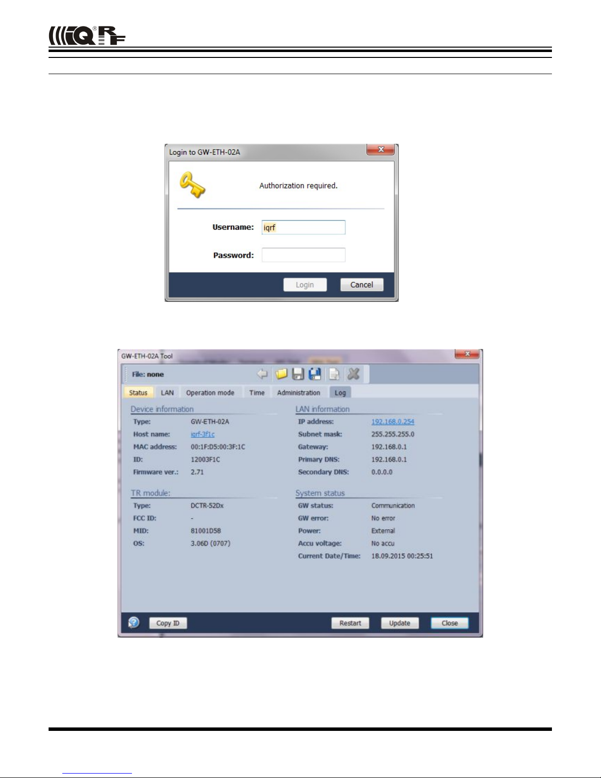
All important events are logged. System logs can be read using IQRF IDE GW Tool or the GW web interface.
Date and time
GW-ET -02A contains a real time clock/calendar (RTCC). Date and time are synchronized using SNTP/Cloud
server.
TR module data exchange
Data between the internal TR module and the GW memory is transferred bidirectionally via SPI (using the
bufferCOM memory array inside the TR module). Therefore, the application in TR must have the SPI communication
activated. When using DPA, a hardware profile with SPI interface must be uploaded in TR. Such plug-in is
uploaded from the factory. The maximum SPI packet length is 64 B.
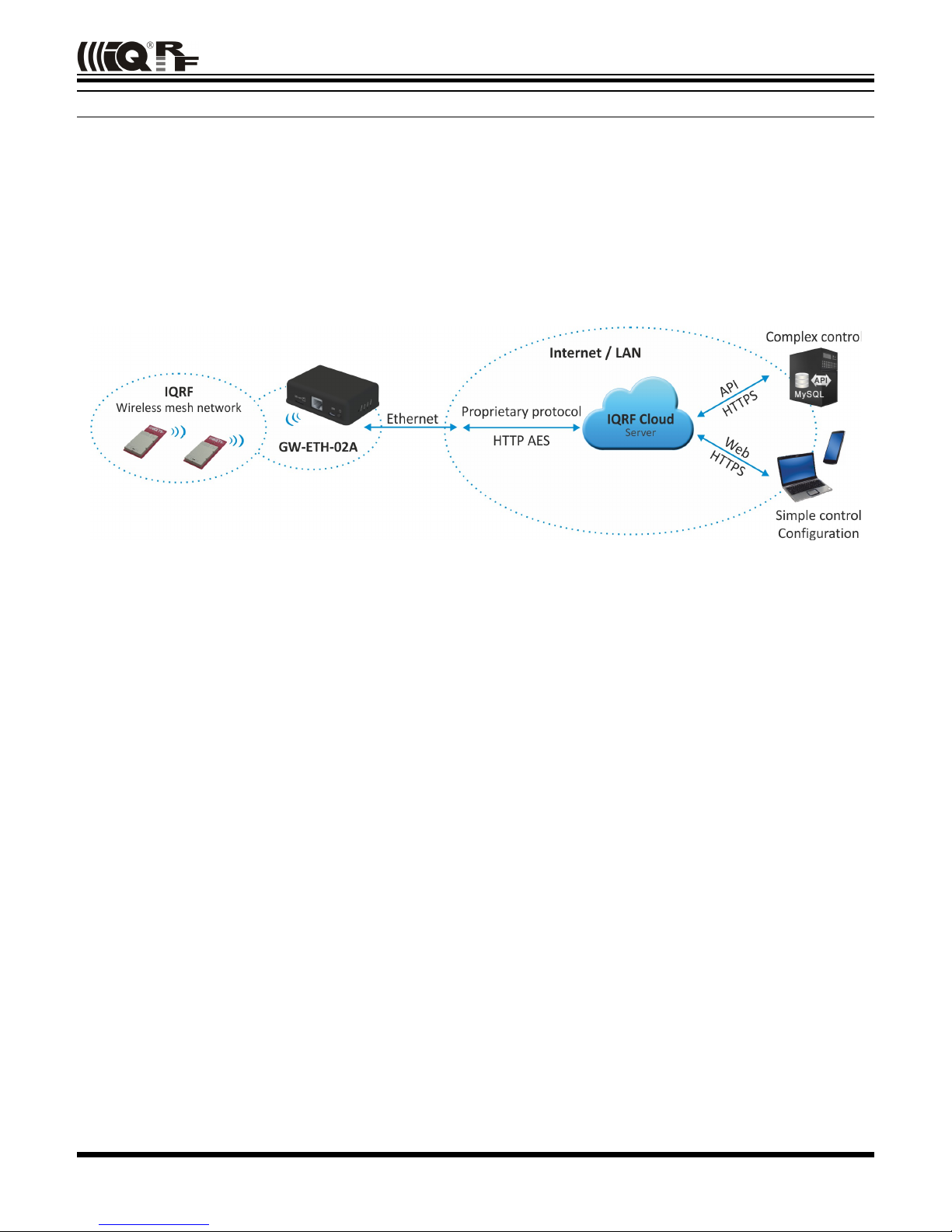
thernet services
•TTP client for communication with IQRF Cloud server (using the 128 b AES encryption)
•TTP server offering web pages for remote management via a common browser
•TTP client for getting and updating of public address from DDNS
•UDP server/client for communication with IQRF network and for remote GW management
•SNTP client for getting date and time from time server
•ICMP server allowing “ping” to GW from a remote host
•D CP client for automated getting of IP address from the D CP server
• NBNS server for using names instead of IP addresses within the LAN
GW identification
MAC address
Every device has a unique MAC address in the format 00 1F D5 xx xx xx, where:
•00 1F D5 is the OUI dedicated to MICRORISC s.r.o.
•xx xx xx is a device serial number
Actual MAC address is printed on the label at the bottom of the GW-ET -02A case.
ID
Another unique number (manufacturer's identification) used to identify the gateway by IQRF IDE, the IQRF Cloud server
and user applications utilizing the Cloud via API.
For GW-ET -02A: ID = 12 xx xx xx, where xx xx xx are last 6 digits of the MAC address.
NBNS Name
iqrf_xxxx, where xxxx are the last 4 digits of the MAC address.
© 2016 MICRORISC s.r.o. www.iqrf.org User_Guide_GW-ET -02A_ 160208 Page 8

GW-ETH-02A
IQ F Cloud
The IQRF Cloud provides an effective way to exchange data between IQRF wireless device(s) and a user
superordinary system implemented by a higher level platform (e.g. P P, JavaScript or web interface) and connected
via Internet or a LAN.
As an interface to IQRF, the GW-ET -02A or another IQRF gateway providing Internet connectivity (Ethernet, GPRS
or WiFi) is intended.
An IQRF Cloud server is available free of charge on http(s)://cloud.iqrf.org provided by CIS (Complete
Internet Services, s.r.o., an IQRF contractual partner for cloud solutions). Moreover, a licensed version is available for
every user of an IQRF gateway prefering to implement and operate one's own IQRF Cloud. Refer to the IQRF Cloud
User's Guide for details.
© 2016 MICRORISC s.r.o. www.iqrf.org User_Guide_GW-ET -02A_ 160208 Page 9

GW-ETH-02A
IQ F IDE – GW Tool
IQRF IDE 4.20 and higher is required.
Login to GW Tool
The GW Tool can be invoked from IQRF IDE menu Tools → GW Tool.
To open the Tool, the username and the password must be entered. Default values are iqrf and iqrf.
Status
The Status tab contains general overview about the gateway status. Several buttons are available to control the GW:
•Copy ID To copy the GW ID to the clipboard
•Restart To restart the gateway
•Update To update the Status tab
•Close To close the GW Tool window
© 2016 MICRORISC s.r.o. www.iqrf.org User_Guide_GW-ET -02A_ 160208 Page 10

GW-ETH-02A
Device information
•Type Current GW type
•ost name Name identification of GW in Ethernet network (used by NBNS)
•MAC address Globally unique identification of GW – Ethernet interface
•ID Unique identification number of the gateway
•Firmware ver. Current firmware version
TR module
•Type IQRF TR module type inside the gateway
•FCC ID FCC certification identification
•MID Unique IQRF TR module identification number
•OS IQRF OS version of the TR module
LAN information
•IP address Current IP address of the GW
•Subnet mask Ethernet network address range
•Gateway Main gateway/server of the Ethernet network
•Primary DNS Primary server with DNS service
•Secondary DNS Secondary server with DNS service
System status
•GW status Current operation executed by the gateway:
•Communication
•Cloud Server Communication
•Error
•GW error An error during execution indication:
•No Error
•TR SPI Error
•LAN Error
•Cloud Server Error
•SD Card Error
•Power „External“ – irrelevant for GW-ET -02A
•Accu voltage „No accu“ – irrelevant for GW-ET -02A
•Current Date/Time The date and time used in the gateway
© 2016 MICRORISC s.r.o. www.iqrf.org User_Guide_GW-ET -02A_ 160208 Page 11

GW-ETH-02A
LAN
The following buttons are available in addition to previous ones:
•Restart To restart the GW with current configuration
•Default To restore the default configuration
•Download To read the configuration from GW
•Upload To store the configuration to GW
LAN
It allows to set/get the parameters relating to Ethernet connection.
•ost name Name identification of GW in the Ethernet network (used by NBNS). If the main gateway/server
offers NBNS service, it is allowed to use this host name instead IP address of GW
•Obtain automatically (D CP) If the main gateway/server offers D CP service, it is allowed to get all LAN
parametres automatically (IP address, Subnet mask, Gateway, Primary DNS,
Secondary DNS)
•IP address Current IP of the GW
•Subnet mask Ethernet network address range
•Gateway Main gateway/server of the Ethernet network
•Primary DNS Primary server with DNS service
•Secondary DNS Secondary server with DNS service
© 2016 MICRORISC s.r.o. www.iqrf.org User_Guide_GW-ET -02A_ 160208 Page 12

GW-ETH-02A
DDNS
DDNS service allows to get public address of network which the GW is assigned in. GW communicates with the
DDNS server in checking interval and transmits its current IP address.
•For IQRF DNS:
The user or user application reads the IP address from the service provider server using the ID of the GW.
•For other DDNS servers:
The user or user application accesses the GW using the ost Name. Refer to the website of given server.
•DDNS DDNS service activation
•Service provider List of supported DDNS servers
•ost name Name identification of GW within DDNS
•User name DDNS account username
•Password DDNS account password
•Check Interval Communication period between the GW and DDNS server
© 2016 MICRORISC s.r.o. www.iqrf.org User_Guide_GW-ET -02A_ 160208 Page 13

GW-ETH-02A
Operation Mode
The Operation mode tab provides the setting of the gateway.
Mode
•Dataloger The datalogger is active. Its content can be read using IQRF Cloud server (if enabled), GW web
server or IQRF IDE GW Tool.
•Gateway UDP channel is active. It is direct connection to the GW (without IQRF Cloud) using the
application protocol described in chapter Application protocol.
Communication ports can be selected in the Gateway field - Port and Remote port.
Logger
•Packet Size The size dedicated for the data log in the gateway memory. By default, this value is set to 64 B,
the same as the maximum size of the IQRF packet. Shorter packets allow to store more data
logs. Minimum packet size is 1 B. When an IQRF packet oversizes the selected packet size, a
part of user data is lost.
When the packet size is changed the content of internal memory is cleared.
IQRF Cloud
•Period Defines how often the gateway transmits the data to IQRF Cloud server. Allowed values are from
2 s to 24 hours.
•Use IQRF Cloud hosted by CIS The gateway is configured by default to communicate with IQRF Cloud server
provided by CIS. Any gateway can also communicate with another IQRF Cloud server provided
by anyone else. In such a case, the checkbox must be unchecked and the following fields must
be filled.
•AES key Encryption key used for secure communication between the gateway and the IQRF Cloud server.
The same key must also be specified at the server side.
•Cloud path The URL address where IQRF Cloud server is hosted. The '/cloud' substring must follow
•Cloud port The TCP port used. In most cases port 80 is used.
Gateway
•GW Port UDP port for the GW side.
•Remote port UDP port for a remote device side.
© 2016 MICRORISC s.r.o. www.iqrf.org User_Guide_GW-ET -02A_ 160208 Page 14

GW-ETH-02A
Time
GW time and date setup.
Set time
•Manual To setup the time manually
•PC time To upload the date and time from connected PC.
Selected time is transferred to the GW by the Set Time button.
GW time
•Current GW Date/Time Date and time currently running in the GW
•Time zone Time zone selection
•Use daylight savings Daylight savings for given time zone selection
•Use SNTP server When activated, the GW time will be synchronized with speicified SNTP server time once
per 6 hours.
•Server SNTP server selection. IQRF Cloud server is also available for this.
© 2016 MICRORISC s.r.o. www.iqrf.org User_Guide_GW-ET -02A_ 160208 Page 15

GW-ETH-02A
Administration
The user can change the username and the gateway password here. When the password is changed, in order to
allow an access the data on the Cloud server it must be changed there too. The change of username has no effect
for that. Allowed password length is from 4 to 8 characters. When the username or the password is lost, the user can
reset the gateway to factory settings. The default username and password values are iqrf and iqrf.
HTTP Server
•Disable remote management Internal web server inside the GW can be disabled. The change takes effect
after GW reset. The configuration through IQRF IDE – GW Tool is possible
even if this option is disabled.
© 2016 MICRORISC s.r.o. www.iqrf.org User_Guide_GW-ET -02A_ 160208 Page 16

GW-ETH-02A
Log
Transmitted data stored on the Cloud server stays also accessible directly in the GW buffer.
Buttons:
•Restart To restart the GW
•Erase Log To erase the content of the whole GW internal log memory
•Update To read the data from the GW and refresh the Log window
•Close To close the GW Tool window
Three types of logs are stored in the gateway:
•IQRF Rx Data received from IQRF network and transmitted to the Cloud server
•IQRF Tx Data downloaded from Cloud server and transmitted to IQRF network
•System Certain events that occurs during the execution. The user do not usually need to take care about it.
Nevertheless it can be helpful in case of nonstandard behavior.
Last Record When selected, the output list is scrolled down to display the last acquired data.
The format of IQRF RX/TX data depends on the user application in TR (e.g. DPA or any user-specific protocol). The
format of system log is fixed. It contains the following information:
© 2016 MICRORISC s.r.o. www.iqrf.org User_Guide_GW-ET -02A_ 160208 Page 17

GW-ETH-02A
The following system events are logged:
•GW_O _BY_EXT_POWER_O
•GW_RESET_FOR_ EW_SETTI GS
•GW_LA _ERROR
•SD_CARD_ERROR
•CLOUD_REGISTRATIO _DO E
•CLOUD_LICE SE_DO E
•CLOUD_CO ECTIO _ERROR
•CLOUD_REGISTRATIO _ERROR
•CLOUD_UPLOAD_ERROR
•CLOUD_DOW LOAD_ERROR
•CLOUD_DOW LOAD_CO F_ERROR
•CLOUD_SYSTEM_PACKET_ERROR
•CLOUD_U K OW _PACKET_RECEIVED
•CLOUD_LICE SE_ERROR
•TR_SPI_ERROR
© 2016 MICRORISC s.r.o. www.iqrf.org User_Guide_GW-ET -02A_ 160208 Page 18

GW-ETH-02A
Web server
The web server inside the GW is primarily intended for GW
configuration and for local reading out from the datalogger. To access
the web server, the IP address of given GW must be known. When
accessing from a local network, the domain name 'iqrf_xxxx'
(where xxxx are last 4 digits of the MAC address) can be used
instead of the IP address. Both GW user name and the GW password
are preset to 'iqrf' from the factory. Every page of the web server
has a help.
It is recommended to change the user name and it is required to
change the GW password as soon as possible, just after the first login
to the web server.
Web server can be enabled/disabled in IQRF IDE GW
Tool/Administration.
The web server implemented inside the GW-ETH-02A should be accessed by any common up-to-date web browser
except of Internet Explorer by icrosoft.
Menu
The main menu provides an access to the configuration pages of GW.
•Status page shows information about the device, current network
connection and the GW status.
•LAN Setup page allows to select the network connection parameters.
•Operation ode page allows to select GW mode which GW works in.
•Dynamic DNS page allows to configure Dynamic DDNS service used to
find the public IP address of the GW.
•Password page allows to change the access parameters for the Web
server, Cloud server and IQRF IDE.
•Time page allows to set the time and date manually or to activate
automatic time synchronization with the selected time server.
•aintenance is intended for fundamental changes in GW and internal TR
functionality.
© 2016 MICRORISC s.r.o. www.iqrf.org User_Guide_GW-ET -02A_ 160208 Page 19

GW-ETH-02A
Status
Device information
•Type GW type
•ost Name Name identification within local network (using this name instead of IP address), in the networks
where NBNS is supported
•MAC Address Globally unique identification of GW device within Ethernet networks
•ID Unique identification of the gateway within the MICRORISC product line
•Firmware Version Current firmware version (and build date)
LAN information
The network connection parameters set manually or obtained through D CP.
TR module
•Type TR module type inside the GW
•MID Unique IQRF TR module identification number
•OS Current version of IQRF OS (and build version) of TR module
•Status: The state which the TR module is in
System status
•GW Status Current operation executed by the gateway. See chapter System status above.
•GW Error: Indicates whether there is an error during execution
•Power Power supply type
•Accu Voltage Not intended for GW-ET -02A
•Current Date/Time Current time of RTCC inside the GW
© 2016 MICRORISC s.r.o. www.iqrf.org User_Guide_GW-ET -02A_ 160208 Page 20
Table of contents
Other IQRF Gateway manuals

IQRF
IQRF GW-USB-04 User manual

IQRF
IQRF GW-USB-13-868 User manual

IQRF
IQRF GW-GSM-02 User manual

IQRF
IQRF GW-USB-03A User manual

IQRF
IQRF GW-USB-05 User manual

IQRF
IQRF GW-GSM-02A User manual

IQRF
IQRF GW-WIFI-01 User manual

IQRF
IQRF GW-USB-13A User manual

IQRF
IQRF GW-USB-06 User manual

IQRF
IQRF GW-ETH-01 User manual