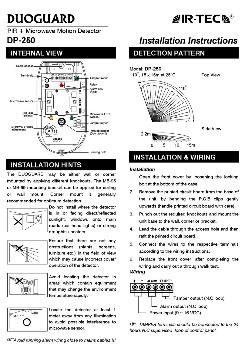
DIP SWITCH SETTING
ON
1 2 3 4 5 6
DIP ON
OFF (Factory set)
PIN 1 - Alarm LED Indication
ALM ON OFF
Red LED ON OFF
PIN 2 - Microwave LED Indication
MW. ON OFF
Green LED ON OFF
PIN 3 & 4 - Pulse count selection
Pulse Count 1 2 3
PC2 (PIN 3) OFF ON OFF
PC1 (PIN 4) ON OFF OFF
PIN 5 - PIR LED Indication
PIR ON OFF
Yellow LED ON OFF
PIN 6 - Trouble output selection
A-M ON OFF
Mode Alarm + Trouble Trouble
ANTI-MASKING & SPRAYING
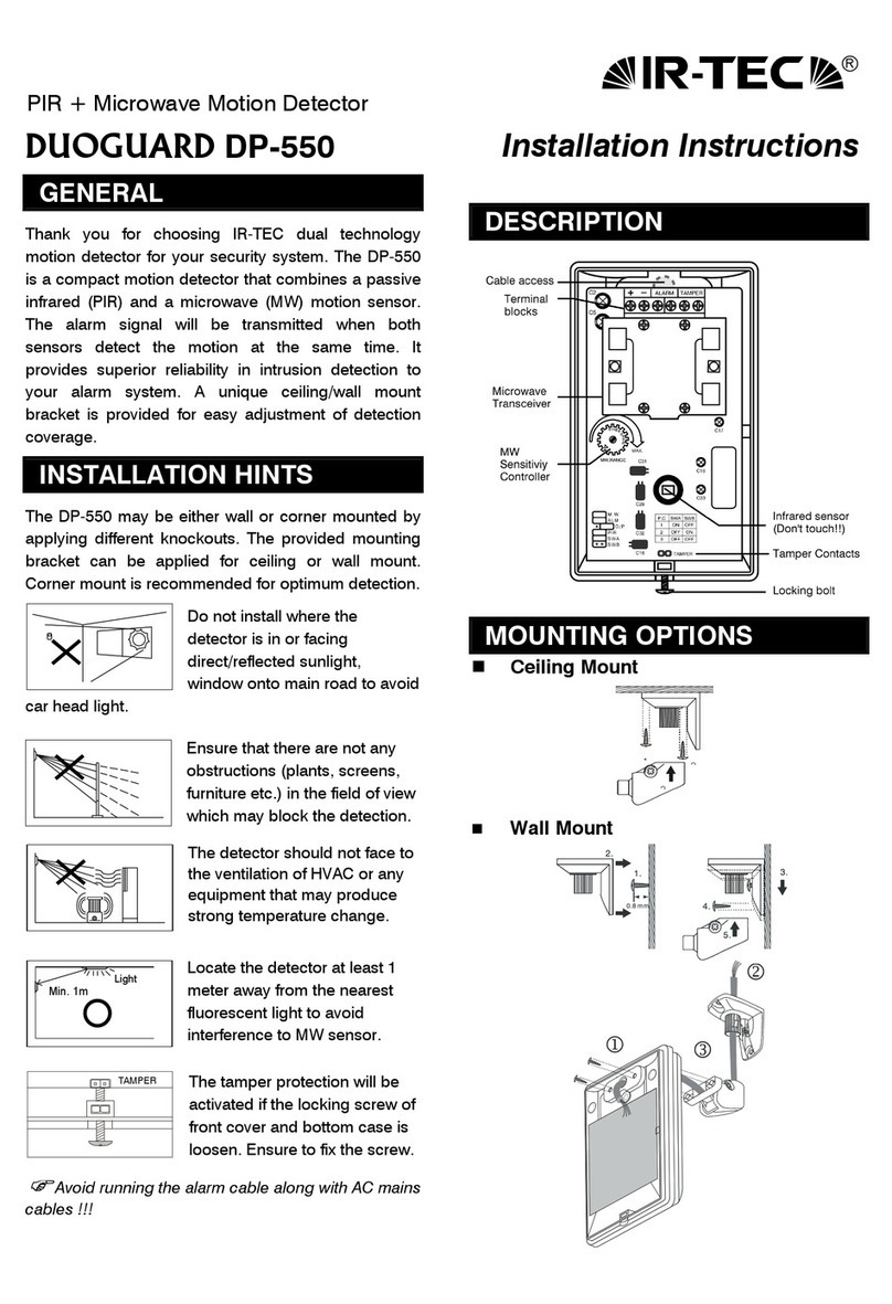
The anti-masking & anti-spraying system detects the
unit being masked or sprayed (masking approximately
25cm or sprayed after 10 seconds). The alarm LED will
latch and a trouble signal is transmitted to the control
panel through “TB” output terminal. The trouble output
format is selected by the “A-M.” PIN 6 switch.
WALK TEST & ADJUSTMENT
It is necessary to carry out a thorough walk test of the
detector to ensure that the correct coverage is being
achieved and no over spill of the microwave is
occurring. Also to ensure that both PIR & microwave
are working to the same detection area.
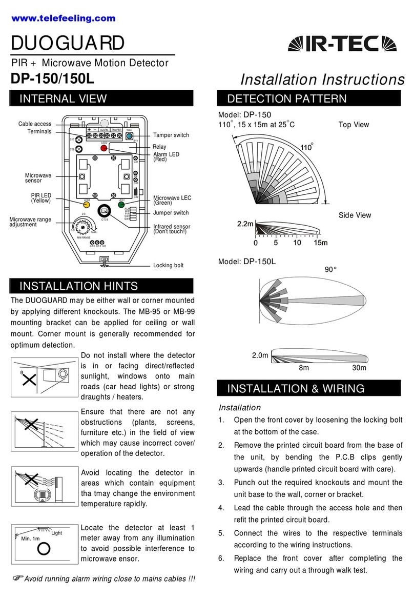
The PIR range sensitivity is NOT
adjustable. Microwave detection range
can be changed by adjusting the
microwave range controller on the front
of the PCB (next to the PIR sensor). The range is
increased by turning the pre-set in clockwise. When
the range is satisfactory, all of the LEDs may be
disabled from DIP switch (please retain for future walk
testing). A remote control voltage may be used to
switch on the LEDs for walk test (available on certain
control panels only a positive 12V) applied to the “LED”
terminal will override the switch setting.
)Regular walk testing must be carried out, as part of
your routine maintenance visits or at least once a
year.)
SPECIFICATIONS
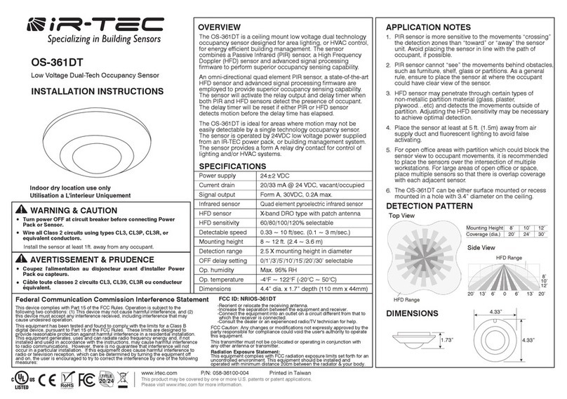
Detection range ......... 15 x 15m at 25°C
Infrared sensor........... Low noise, dual element
Microwave sensor...... Micro strip antenna type
MW output power....... 6 mW E.I.R.P. peak
Power supply ............. 9 ~ 16 VDC (12 VDC nominal)
Current drain.............. 37mA at 12 VDC
Alarm period .............. 2 ±0.5 sec.
Alarm output .............. N.C 30 VDC, 0.2A max.
Trouble signal ............ Normal: 12V, trouble: 0V
Anti-masking .............. About 25cm (10”) for 10
seconds
Alarm output LED ......Red, can be disabled
MW sensor LED......... Green, can be disabled
PIR sensor LED ......... Yellow, can be disabled
Pulse count ................ 1, 2, 3 selectable
Tamper protection...... N.C cover open activates
RFI immunity.............. Ave. 30V/m (10~1000 MHz)
Mounting height ........2.0 ~ 2.4m (wall/corner mounted)
2.4 ~ 3.6m (with bracket)
Mounting bracket ....... MB-95 or MB-99 (Optional)
Temperature .............. -10°C ~ 55°C (14°F ~ 131°F)
Detection zones ......... 68 zones
Humidity..................... 95% RH max.
Dimensions ................ 125 x 68 x 42mm
Unit weight ................ 130 grams
Specifications are subject to change without prior notice.
Shepherd System DP-150A Eng. I/M V1.0
MIN.
MAX.
MW. RANGE
