manuals.online logo
Brands
  1. Home
  2. •
  3. Brands
  4. •
  5. IR-Tec
  6. •
  7. Security Sensor
  8. •
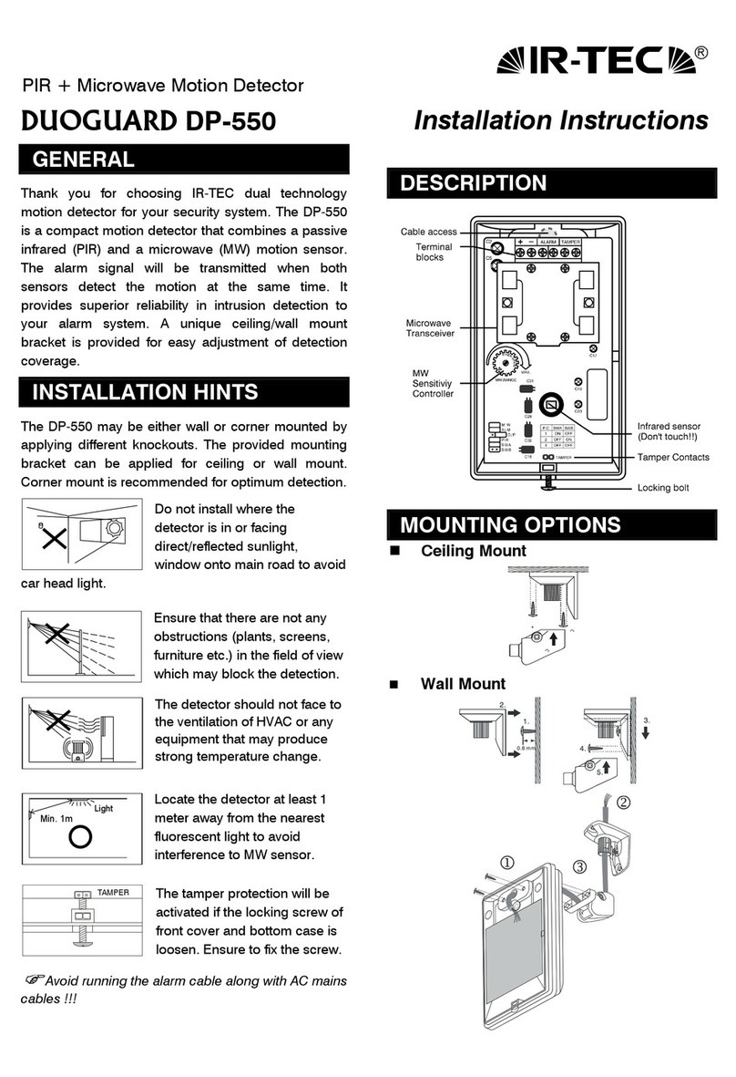
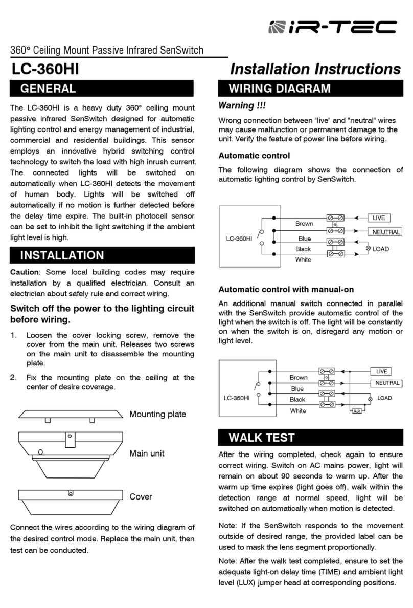
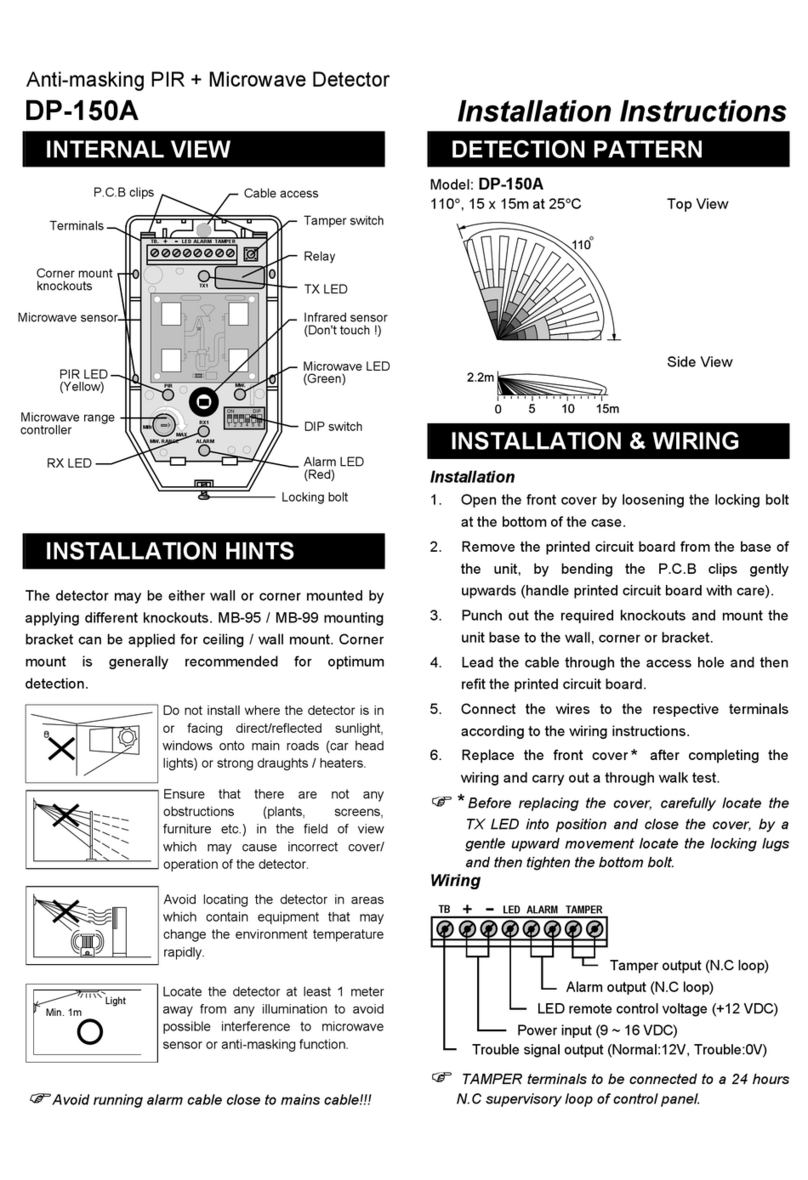
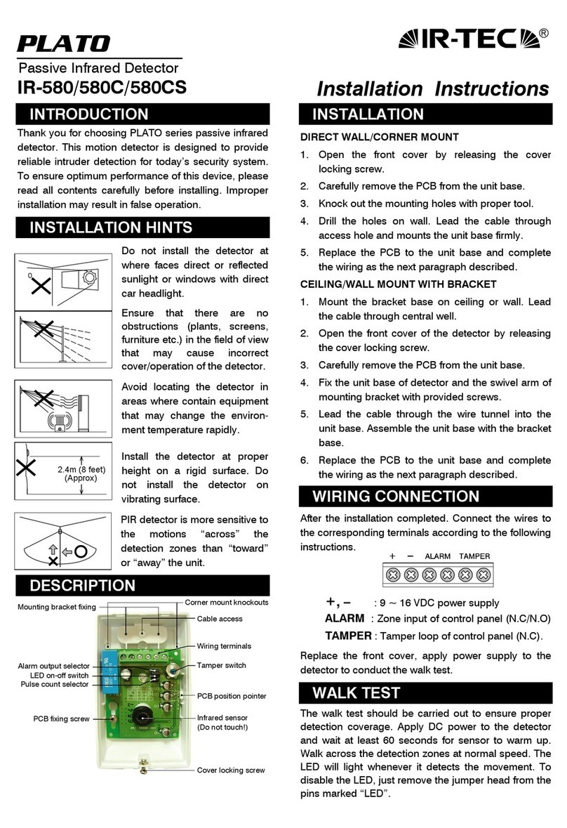
  9. IR-Tec OS-361DT User manual

IR-Tec OS-361DT User manual

Top View
Mounting Height
Coverage (dia.)
8’
20’
10’
24’
12’
30’
Side View
20’ 13’ 6’ 0 6’ 13’ 20’
12’
10’
8’
HFD Range
HFD Range
OVERVIEW
The OS-361DT is a ceiling mount low voltage dual technology
occupancy sensor designed for area lighting, or HVAC control,
for energy efficient building management. The sensor
combines a Passive Infrared (PIR) sensor, a High Frequency
Doppler (HFD) sensor and advanced signal processing
firmware to perform superior occupancy sensing capability.
An omni-directional quad element PIR sensor, a state-of-the-art
HFD sensor and advanced signal processing firmware are
employed to provide superior occupancy sensing capability.
The sensor will activate the relay output and delay timer when
both PIR and HFD sensors detect the presence of occupant.
The delay timer will be reset if either PIR or HFD sensor
detects motion before the delay time has elapsed.
The OS-361DT is ideal for areas where motion may not be
easily detectable by a single technology occupancy sensor.
The sensor is operated by 24VDC low voltage power supplied
from an IR-TEC power pack, or building management system.
The sensor provides a form A relay dry contact for control of
lighting and/or HVAC systems.
Low Voltage Dual-Tech Occupancy Sensor
OS-361DT
INSTALLATION INSTRUCTIONS
APPLICATION NOTES
SPECIFICATIONS
Power supply
Current drain
Signal output
Infrared sensor
HFD sensor
HFD sensitivity
Detectable speed
Mounting height
Detection range
OFF delay setting
Op. humidity
Op. temperature
Dimensions
24±2 VDC
20/33 mA @ 24 VDC, vacant/occupied
Form A, 30VDC, 0.2A max.
Quad element pyroelectric infrared sensor
X-band DRO type with patch antenna
60/80/100/120% selectable
0.33 ~ 10 ft/sec. (0.1 ~ 3 m/sec.)
8 ~ 12 ft. (2.4 ~ 3.6 m)
2.5 X mounting height in diameter
0/1’/3’/5’/10’/15’/20’/30’ selectable
Max. 95% RH
-4°F ~ 122°F (-20°C ~ 50°C)
4.4” dia. x 1.7” depth (110 mm x 44mm)
PIR sensor is more sensitive to the movements “crossing”
the detection zones than “toward” or “away” the sensor
unit. Avoid placing the sensor in line with the path of
occupant, if possible.
PIR sensor cannot “see” the movements behind obstacles,
such as furniture, shelf, glass or partitions. As a general
rule, ensure to place the sensor at where the occupant
could have clear view of the sensor.
HFD sensor may penetrate through certain types of
non-metallic partition material (glass, plaster,
plywood…etc) and detects the movements outside of
partition. Adjusting the HFD sensitivity may be necessary
to achieve optimal detection.
Place the sensor at least at 5 ft. (1.5m) away from air
supply duct and fluorescent lighting to avoid false
activating.
For open office areas with partition which could block the
sensor view to occupant movements, it is recommended
to place the sensors over the intersection of multiple
workstations. For large areas of open office or space,
place multiple sensors so that there is overlap coverage
with each adjacent sensor.
The OS-361DT can be either surface mounted or recess
mounted in a hole with 3.4” diameter on the ceiling.
1.
2.
3.
4.
5.
6.
DIMENSIONS
1.73” 4.33”
4.33”
DETECTION PATTERN
P/N: 058-36100-004 Printed in Taiwanwww.irtec.com
This product may be covered by one or more U.S. patents or patent applications.
Please visit www.irtec.com for more information.
Turn power OFF at circuit breaker before connecting Power
Pack or Sensor.
Wire all Class 2 circuits using types CL3, CL3P, CL3R, or
equivalent conductors.
Coupez l'alimentation au disjoncteur avant d'installer Power
Pack ou capteurs.
Câble toute classes 2 circuits CL3, CL39, CL3R ou conducteur
équivalent.
FCC ID: NRIOS-361DT
Federal Communication Commission Interference Statement
This device complies with Part 15 of the FCC Rules. Operation is subject to the
following two conditions: (1) This device may not cause harmful interference, and (2)
this device must accept any interference received, including interference that may
cause undesired operation.
This equipment has been tested and found to comply with the limits for a Class B
digital device, pursuant to Part 15 of the FCC Rules. These limits are designed to
provide reasonable protection against harmful interference in a residential installation.
This equipment generates, uses and can radiate radio frequency energy and, if not
installed and used in accordance with the instructions, may cause harmful interference
to radio communications. However, there is no guarantee that interference will not
occur in a particular installation. If this equipment does cause harmful interference to
radio or television reception, which can be determined by turning the equipment off
and on, the user is encouraged to try to correct the interference by one of the following
measures:
-Reorient or relocate the receiving antenna.
-Increase the separation between the equipment and receiver.
-Connect the equipment into an outlet on a circuit different from that to
which the receiver is connected.
-Consult the dealer or an experienced radio/TV technician for help.
FCC Caution: Any changes or modifications not expressly approved by the
party responsible for compliance could void the user's authority to operate
this equipment.
This transmitter must not be co-located or operating in conjunction with
any other antenna or transmitter.
Radiation Exposure Statement:
This equipment complies with FCC radiation exposure limits set forth for an
uncontrolled environment. This equipment should be installed and
operated with minimum distance 20cm between the radiator & your body.
WARNING & CAUTION
AVERTISSEMENT & PRUDENCE
Indoor dry location use only
Utilisation a L'interieur Uniquement
Install the sensor at least 1ft. away from any occupant.
OS-361DT
DC
Line Black
White
Red
Red
Red
Black
Green
White
Red
Neut
Relay
Relay
DC24V
DC
COM
NO
Control
Load
Line
120/277V
Neutral
Black
Blue
PPU-300/301
Line Black
White
Red
Orange
Grey
Brown
Red
Neut
Relay
Relay
DC24V
DC
COM
NO
Control
Manual
Hold ON
Hold OFF
Load
Momentary Button
Line
120/277V
Neutral
Red
Black
Green
White
Red
Black
Blue
DC
OS-361DT
PPU-300
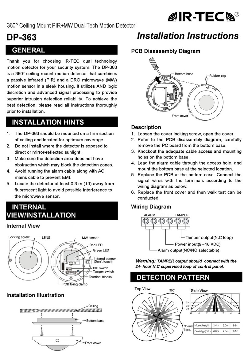
The OS-361DT is an occupancy sensor which combines two
different sensing technologies, PIR and HFD, in one housing
for ceiling mount installation. The sensor is operated by 24
VDC low voltage power. Whenever the sensor detects the
presence of occupant, its dry contact relay output will be
engaged for the delay time programmed. The delay timer
will be reset if any motion is detected by either PIR or HFD
sensor before delay time elapses.
8 different delay times and 4 different HFD sensitivity levels
can be programmed via specific DIP switch combinations.
2 LED’s are available to indicate the operation of PIR and
HFD sensors respectively. The sensor operation LED can be
disabled by specific DIP switch, if necessary.
It is recommended to conduct a walk test to verify optimum
coverage after sensor installed. To test the sensor range,
restore the front cover, apply the low voltage power and wait
approximately 90 seconds for sensor to warm up. The LED
will blink during warm-up period. Walk into the projected
area in the path of occupant show up and observe if the
sensor can detect the presence. The LED will be lit
whenever sensor detects the motion. If the space has
multiple entrances, repeat the test in all available paths.
HFD sensor could possibly detect the movements outside of
certain type of dry wall or partition. If happened, sensitivity
can be adjusted by changing the ON-OFF combinations of
DIP switch #1 and #2 as the following table shows.
2 LED’s are available to indicate the status of PIR and HFD
sensor operation. The LED indication can be disabled by
setting the SW #3 to OFF position.
A 6-pole DIP switch is available for various sensor settings via
combinations of ON and OFF positions of specific switch.
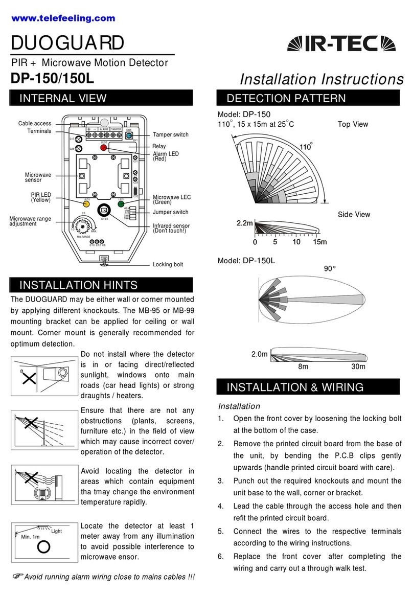
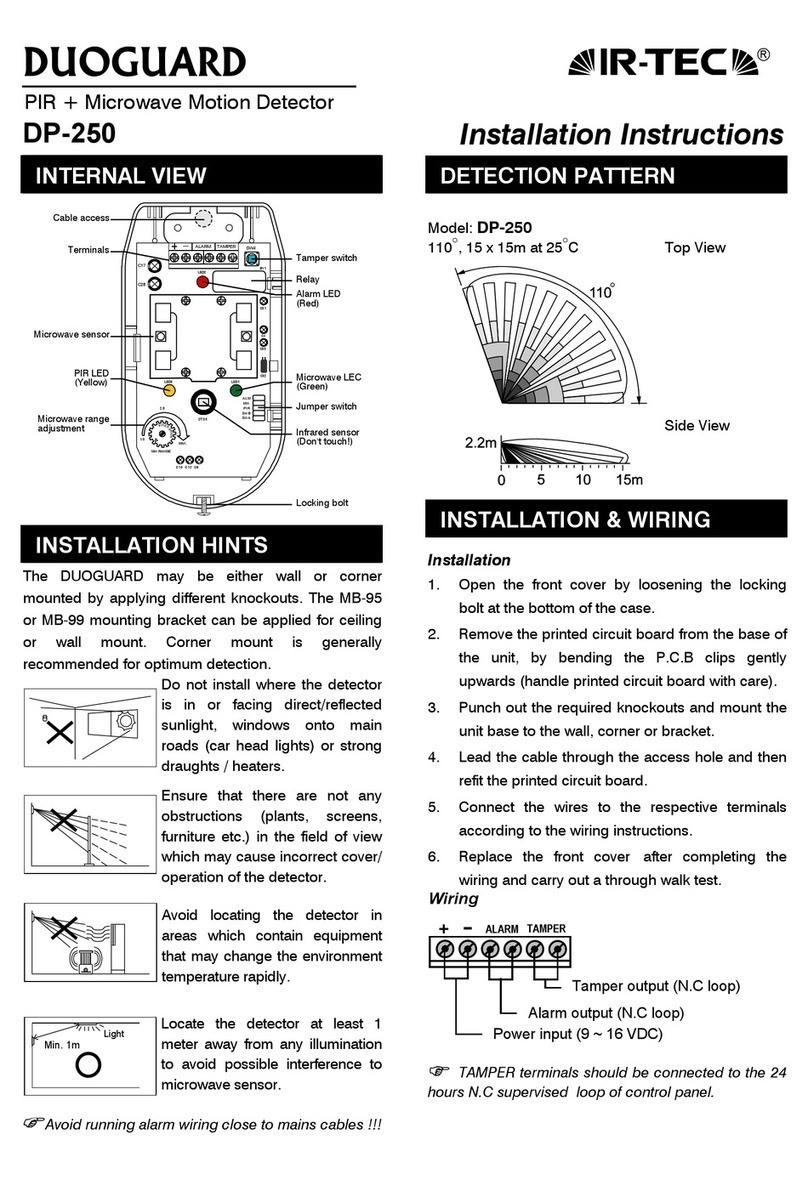
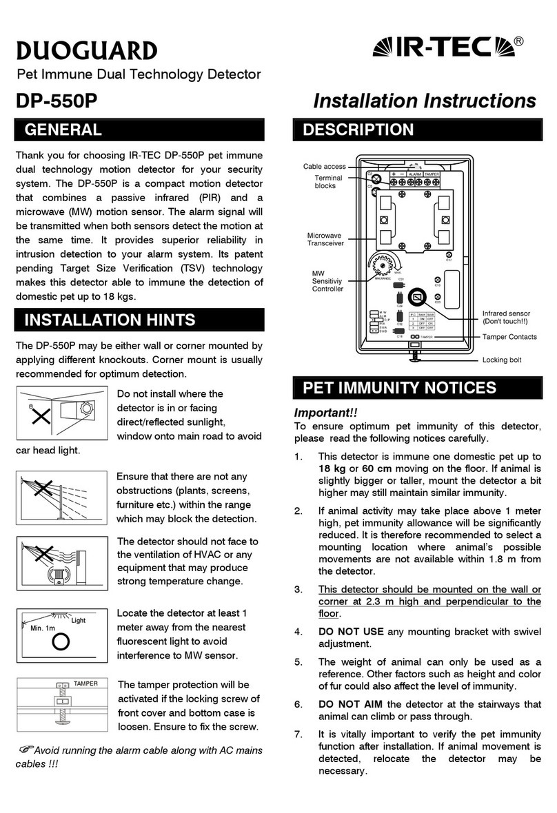
Various control modes may be achieved by different wiring
connections. The following diagrams are typical control for
reference. For the availability of more complex control,
please contact an IR-TEC team member directly.
NOTE: Each IR-TEC PPU-300/301 power pack can supply
power for up to 3 OS-361DT sensors. When more sensors
are connected, multiple power packs may be required.
IR-TEC International Ltd. warranties this product to be free
of defects in materials or workmanship for a period of five
years from date of shipment. There are no obligations or
liabilities on the part of IR-TEC International Ltd. for
consequential damages arising out or in connection with the
use or performance of this product or other indirect
damages with respect to loss of property, revenue, or profit,
or cost of removal, installation or reinstallation.
WARRANTY
SENSOR OPERATION MOUNTING THE SENSOR
HFD SENSITIVITY – SW #1 & #2
LED ON/OFF – SW #3
Total 8 different delay times can be selected via the combinations
of SW #4, #5 and #6 as the following table shows.
OFF DELAY – SW #4, #5, & #6
RANGE TEST
SENSOR SETTINGS
SENSOR INTERNAL
WIRING DIAGRAM
Loosen the locking screw to the position where the front
cover can be removed. Leave the screw attached with
Connect the wire leads with IR-TEC power pack or BMS
as per wiring diagram of the desired control.
Mount the sensor base with screws provided. For
surface mount, use two knockout holes underneath both
sides of the PCBA. For recess mount, use two holes on
the flange of sensor base.
Replace the front cover and tighten the locking screw.
1.
2.
3.
4.
B. Manual-ON/Auto-OFF with PPU-300
A. Auto-ON/Auto-OFF
The supplied rubber pad can be used to cover the
locking screw for aesthetic purpose.
The respective LED will light on whenever PIR (blue)
or HFD (green) sensor detects the motion.
Note:
Stay out of sensor coverage during warm-up to
avoid extending the period.
Note:
Infrared sensor
HFD Sensor LED
HFD Sensor
PIR Sensor LED
DIP Switch (Don't touch!!)
Recess Mount Knockout
Surface
Mount Knockout
Surface Mount
Knockout
60% 80% 100% 120%
ON
1 2 3 4 5 6
ON
1 2 3 4 5 6
ON
1 2 3 4 5 6
ON
1 2 3 4 5 6
*
*
10 min. 15 min. 20 min. 30 min.
0 sec. 1 min. 3 min. 5 min.
ON
1 2 3 4 5 6
ON
1 2 3 4 5 6
ON
1 2 3 4 5 6
ON
1 2 3 4 5 6
ON
1 2 3 4 5 6
ON
1 2 3 4 5 6
ON
1 2 3 4 5 6
ON
1 2 3 4 5 6
* Factory Set
*Factory Set

Other IR-Tec Security Sensor manuals

IR-Tec ACTIVATA LC-200 User manual

IR-Tec

IR-Tec ACTIVATA LC-200 User manual

IR-Tec LC-360HI User manual

IR-Tec

IR-Tec LC-360HI User manual

IR-Tec DP-363 User manual

IR-Tec

IR-Tec DP-363 User manual

IR-Tec DUOGUARD DP-550P User manual

IR-Tec

IR-Tec DUOGUARD DP-550P User manual

IR-Tec Plato IR-580 User manual

IR-Tec

IR-Tec Plato IR-580 User manual

IR-Tec DUOGUARD DP-250 User manual

IR-Tec

IR-Tec DUOGUARD DP-250 User manual

IR-Tec DUOGUARD DP-550 User manual

IR-Tec

IR-Tec DUOGUARD DP-550 User manual

IR-Tec DUOGUARD DP-150 User manual

IR-Tec

IR-Tec DUOGUARD DP-150 User manual

IR-Tec DUOGUARD DP-550 User manual

IR-Tec

IR-Tec DUOGUARD DP-550 User manual

IR-Tec DP-150A User manual

IR-Tec

IR-Tec DP-150A User manual

Popular Security Sensor manuals by other brands

Siemens Sinteso FD20 Guideline

Siemens

Siemens Sinteso FD20 Guideline

ZBL Science & Technology ZBL-R800 Operation manual

ZBL Science & Technology

ZBL Science & Technology ZBL-R800 Operation manual

Littfinski Daten Technik SX-GB-8-B Assembly instruction

Littfinski Daten Technik

Littfinski Daten Technik SX-GB-8-B Assembly instruction

Inficon D-TEK Stratus operating manual

Inficon

Inficon D-TEK Stratus operating manual

jablotron JA-180PB quick start guide

jablotron

jablotron JA-180PB quick start guide

DANLERS CBU-HBND IP66 quick guide

DANLERS

DANLERS CBU-HBND IP66 quick guide

Smarteh LBT-1.B01 user manual

Smarteh

Smarteh LBT-1.B01 user manual

Riken Keiki RX-516 Operation manual

Riken Keiki

Riken Keiki RX-516 Operation manual

Fastus CD22 Series instruction manual

Fastus

Fastus CD22 Series instruction manual

Grizzly H7786 Parts Breakdown

Grizzly

Grizzly H7786 Parts Breakdown

Lince ZENITH IR manual

Lince

Lince ZENITH IR manual

Samsung SIA-0120D user manual

Samsung

Samsung SIA-0120D user manual

CS Instruments LD 400 operating manual

CS Instruments

CS Instruments LD 400 operating manual

HPM AQUAscan instruction manual

HPM

HPM AQUAscan instruction manual

Gas Clip Technologies Multi Gas Clip Simple user manual

Gas Clip Technologies

Gas Clip Technologies Multi Gas Clip Simple user manual

ipf electronic UT990895 manual

ipf electronic

ipf electronic UT990895 manual

yellow jacket 69373 Series Installation and operation manual

yellow jacket

yellow jacket 69373 Series Installation and operation manual

ELTEX ETM Solo Viewer manual

ELTEX

ELTEX ETM Solo Viewer manual

manuals.online logo
manuals.online logoBrands
  • About & Mission
  • Contact us
  • Privacy Policy
  • Terms and Conditions

Copyright 2025 Manuals.Online. All Rights Reserved.