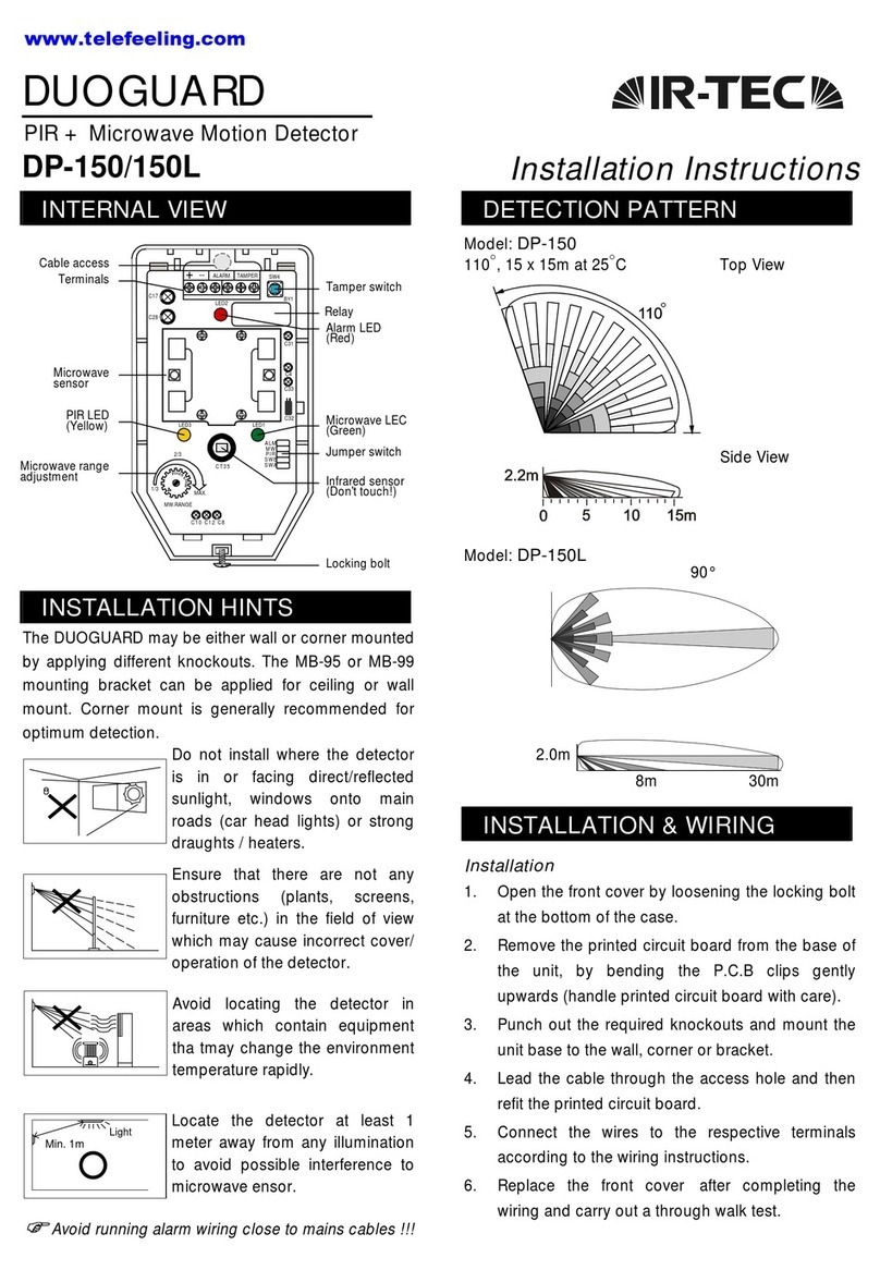
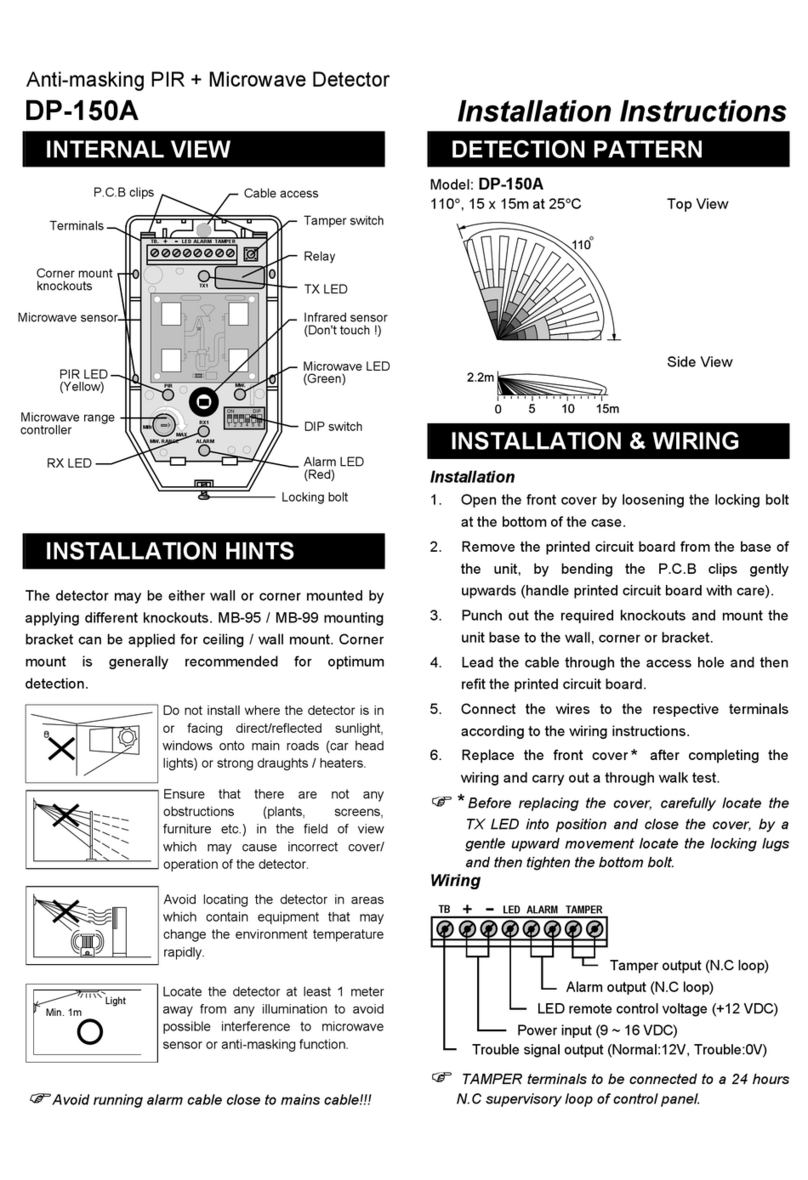
JUMPER SWITCH SETTING
MW
ALM
PIR
SWB
SWA
ON OFF
(Factory set)
ALM - Alarm LED Indication
ALM jumper ON OFF
Red LED ON OFF
MW - Microwave LED Indication
MW. jumper ON OFF
Green LED ON OFF
PIR - PIR LED Indication
PIR jumper ON OFF
Yellow LED ON OFF
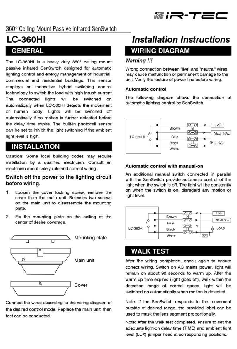
SWA, SWB - Pulse count selection
Pulse Count 1 2 3
SWA jumper ON OFF OFF
SWB jumper OFF ON OFF
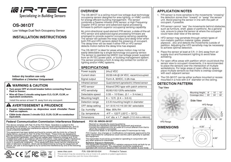
WALK TEST & ADJUSTMENT
It is necessary to carry out a thorough
walk test of the detector to ensure that
the correct coverage is being achieved
and no over spill of the microwave is
occurring. Also to ensure that both PIR & microwave
are working to the same detection area.
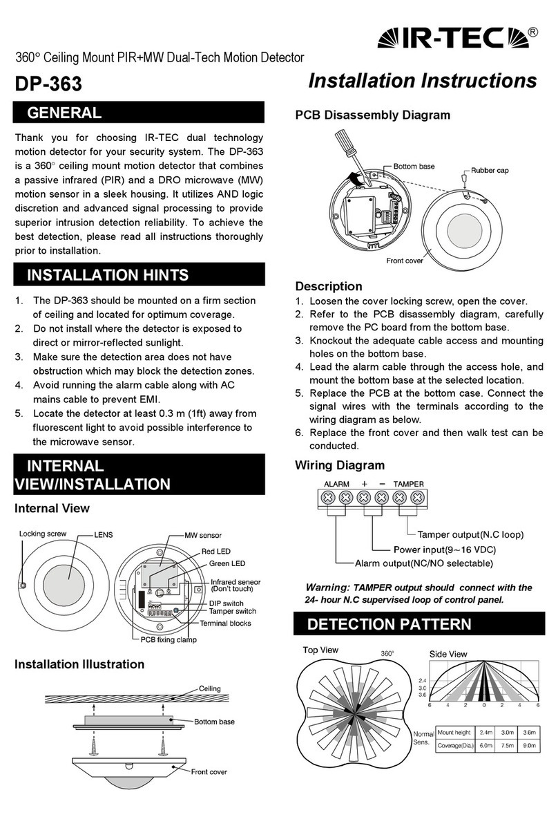
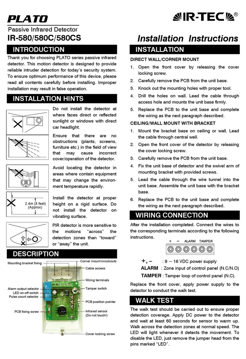
The PIR range sensitivity is not adjustable. Accurate
setting of the microwave is achieved by careful
adjustment of the microwave range controller on the
front of the PCB, next to the PIR detector, the range is
increased by turning the pre-set in clockwise direction.
When you are satisfied with your setting, all of the
LEDs may be disable from jumper switch (please
retain for future walk testing).
)Regular walk testing must be carried out, as part of
your routine maintenance visits or at least once a
year.)
MOTION SIGNAL DISCRETION
The MSD (Motion Signal Discretion) circuit recognizes
the difference between motion and non-motion signals.
Alarm output is only generated when motion is
detected by infrared & microwave sensor and
analyzed by the MSD circuit. MSD circuit ensures
supreme reliability even when environmental
conditions are severe.
SPECIFICATIONS
Detection range ........15 x15 m at 25°C
Infrared sensor………Low noise, dual element
Microwave sensor.....DRO w/m micro strip antenna
MW Frequency .........10.525 GHz
MW output power .....6 mW E.I.R.P. peak
Power supply............9 ~ 16 VDC (12 VDC nominal)
Current drain.............30mA at 12 VDC
Alarm period .............2 ±0.5 sec.
Alarm output .............N.C 30 VDC, 0.2A max.
Alarm output LED .....Red, can be disabled
MW sensor LED........Green, can be disabled
PIR sensor LED.........Yellow, can be disabled
Pulse count...............1, 2, 3 selectable
Tamper protection ....N.C cover open activates
RFI immunity.............Ave. 20V/m (10~1000 MHz)
Mounting height........2.0~ 2.4m (wall/corner mounted)
2.4~ 3.6m (with bracket)
Mounting bracket......MB-95 or MB-99 (Optional)
Temperature .............-10°C ~ 55°C (14°F ~ 131°F)
1/3
MAX
MW RANGE
2/3
Humidity....................95% RH max.
Dimensions...............132 x 72 x 57mm
Unit weight ...............110 grams
To continue improving produc qualityt, IR-TEC reserves the
right to change specifications without prior notice.
Warning: Changes or modifications this nit not expressly
approved by the party responsible for compliance could void
the user’s authority to operate the eqipment.
This device complies with Part 15 of the FCC Rules.
Operation is subject to the following two conditions:
(1) This device may not cause harmful interference, and
(2) This device must accept any interference received,
Including interference that may cause undesired
operation.

