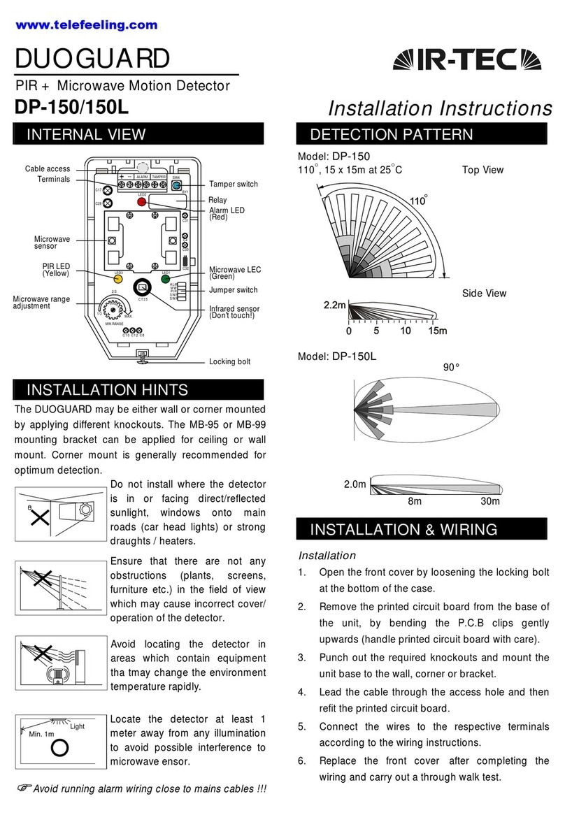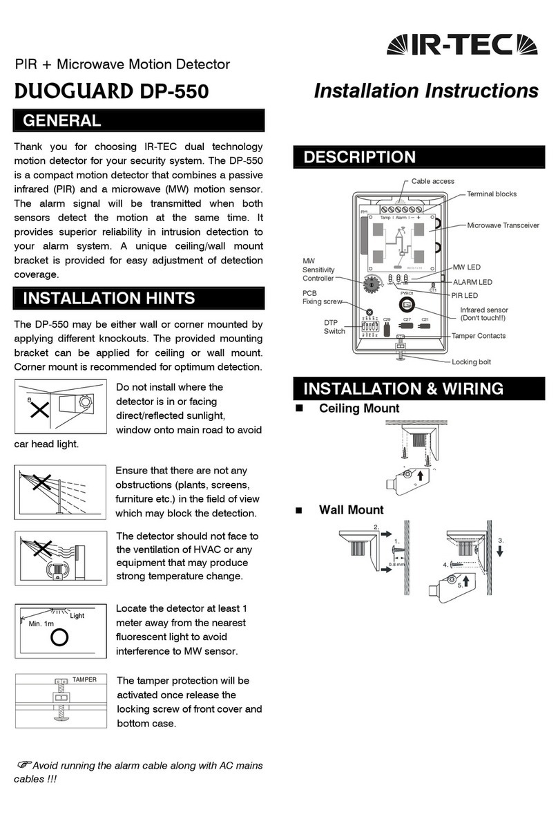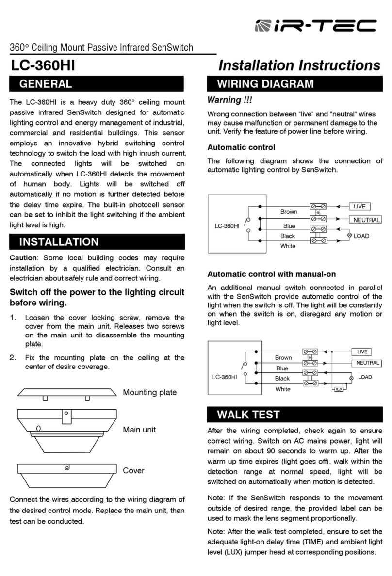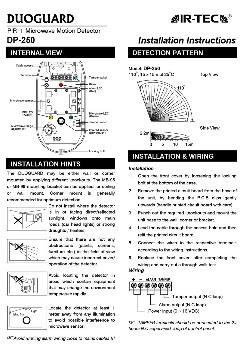
FUNCTIONSETTING
SW1DIPswitchisavailableforall function settingsof
the detector.Pleaserefertothe following instructions
forsetting options.
Function Setting Indication
SW# 1 2 3 4 5 6
Function
Setting
Pulse
Count
Trigger
Count
LED
ON/OFF
Alarm
Output
MWSensitivity
ON 3ON ON NC
OFF 1OFF OFF NO
(Refertonext
table)
MicrowaveSensitivitySetting
MW
Sensitivity
60% 80% 100% 120%
Detection
Coverage
(@3mhigh)
4x4m 6x6m 8x8m
(default)
12x12m
Switch
Setting
1. Pulse Count
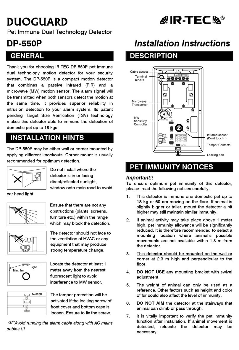
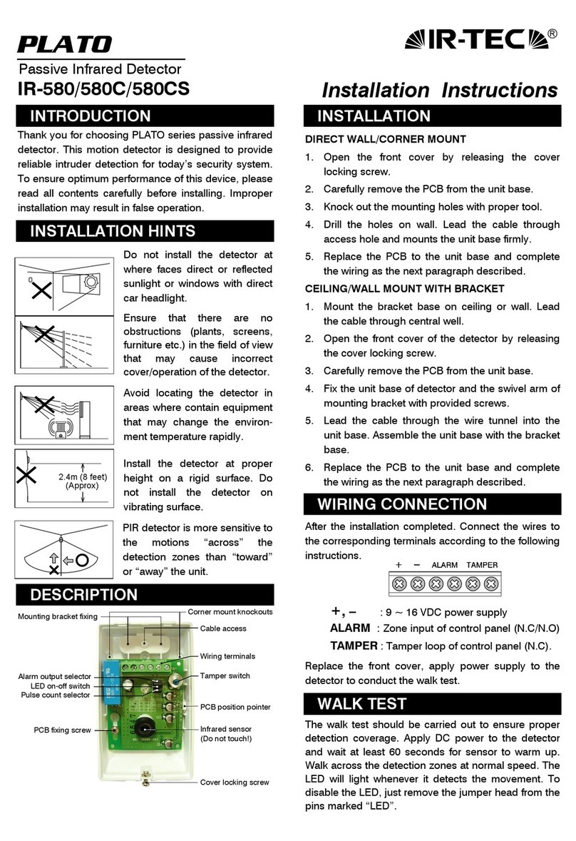
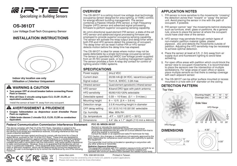
The DP-363 featuresintelligentpulsecountinitsPIR
sensorwhichcan effectivelypreventfalsealarms
causebyenvironmentalinterference. If itisinstalled at
the placeswithrapidtemperaturechange orunknown
electricalinterference,DIPswitch#1 whichcontrols
the PIRpulsecountcan be settoONposition for3
pulsestoincreasethe detection reliability.
2. TriggerCount
When pulsecountisalreadyseton,and the detector
still experiencesfalsealarmcaused byunknownfactor,
then TriggerCount”can be enabled.Withtrigger
countenabled,the detectorwill holdthe alarmoutput
forashortperiod oftimeand releasethe alarmsignal
onlywhen atrue intrusion isverified bysophisticated
signalprocessing software.
Warning:Once thetrigger countisenabled, the
alarm outputwill beslower thannormal. Thus,
walktestmustbeconductedtoensure that
detectornotto miss catching theintrusion.
3. LEDIndication
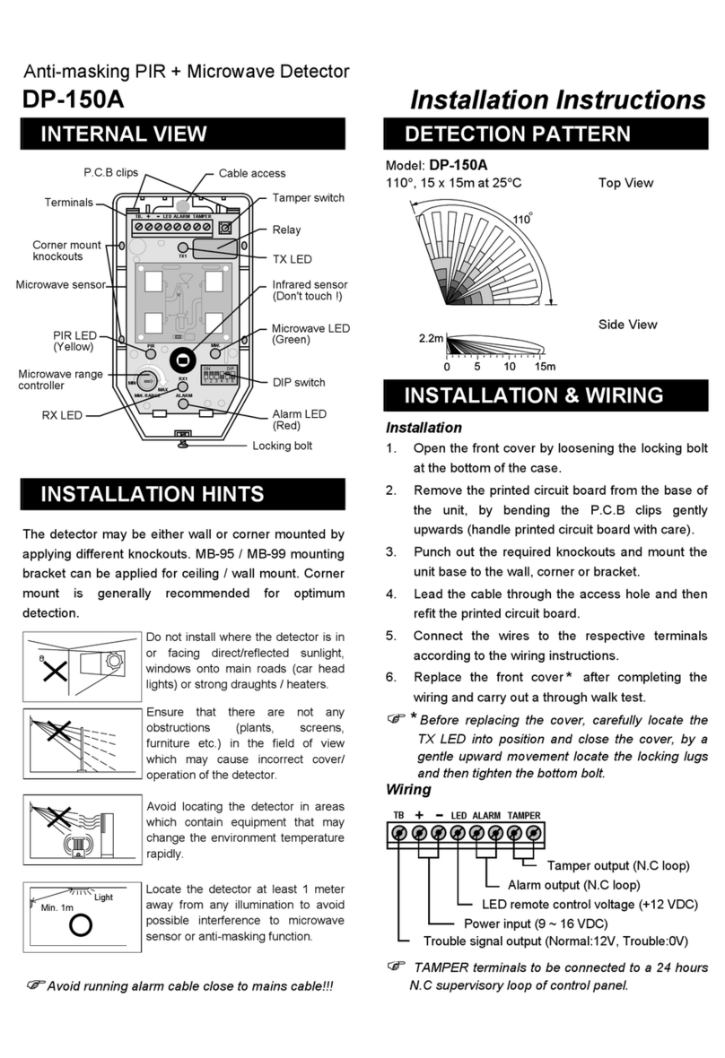
The LEDofDP-363 indicatesthe operation statusof
the detector.When the green LEDlightsup,itmeans
the MW sensorisactive.When the red LEDlightsup,
itshowsthe alarmoutput(alsorepresentsthe infrared
sensorisactive).Ifitisnecessary todisablethe LED
indication, just set DIPswitch#3 toOFF position.
WALK TEST&ADJUSTMENT
Pleaserefertothe following instructionstoconduct
walktest and MWadjustment.
WalkTest
1. ApplyDC powersupplyand waitabout60
secondsforsensortowarmup.During warmup
period, bothred and green LEDswill light up.
2. Afterthe warmup timeexpires,walkacross the
detection area atnormalspeed.Check ifthe red
and green LEDturnon/off following bytester’s
walk/stop.
SensitivityAdjustment
Ifthereisno movementwithinthe detection range and
the green LEDremainson, thismeansthat MWsensor
isprobablyoversensitive(usuallyappearsinasmaller
room).Pleasereducethe MWsensitivityin
accordancewiththe MWsensitivitysetting table.
Note:Regular walktestmustbecarriedout,as
partofroutinemaintenance atleastonce ayear.
Themounting heightshould beatleastat2.4m.
SPECIFICATIONS
MWfrequency 10.525GHz
MWoutput power 10dBmEIRP
Powersupply 9 16VDC (12 VDC nominal)
Current drain 17mA@12VDC
Infrared sensor Omni-directional, dualelement,
lownoise
Microwavesensor DRO w/mmicrostripantenna
Mounting height 2.4 3.6m
Alarmperiod 2 4sec.
Alarmoutput NC/NO, selectable, 30VDC,
0.2Amax.
Warmup period 60sec.Red/Green LEDon
Alarmoutput LED Red, can be disabled
MWsensorLED Green, can be disabled
Tamperprotection NC, coveropen activates
Pulsecount PIR1/3, selectable
Op. temperature -20°C55°C(-4°F~131°F)
Dimensions 110 (dia.)x44mm (H)
06/07’058-36321-001
FCC ID: NRIDP363
This devicecomplies withPart 15 ofthe FCC Rules.
Operation is subject tothe following twoconditions:
(1) Thisdevicemaynotcauseharmful interference,
and
(2) This devicemust accept any interferencereceived,
Including interferencethat may causeundesired
operation.
lThe black blocks
indicateswitchposition.
lThe left showsfactory
default setting.
