Iron-A-Way UD-42 User manual

IRONING CENTER
INSTALLATION MANUAL
SUPPLIED PARTS
Quick Reference
SUPPLIES NEEDED
SWIVEL MODELS
AE-46 ANE-46 AE-42 ANE-42 UD-42
RECESSED INSTALLATION
#10 x 1 1/2” Wood Screws (2)
#14 x 2 1/2” Phillips Screws (2)
SURFACE MOUNT INSTALLATION
#14 x 4” Wood Screws (2)
NON-SWIVEL MODELS
E-46 NE-46 E-42 NE-42 IAW-42
RECESSED INSTALLATION
#10 x 1 1/2” Wood Screws (4)
SURFACE MOUNT INSTALLATION
#14 x 4” Wood Screws (2)
IAW-42 ONLY
#14 x 2 1/2” Wood Screws (2)
Swivel Models
pg. 2 | Pre-Installation
pg. 3 | Recessed Mount
pg. 4 | Surface Mount
pg. 7 | Electrical
Non-Swivel Models
pg. 2 | Pre-Installation
pg. 5 | Recessed Mount
pg. 6 | Surface Mount
pg. 7 | Electrical
Carpenter’s Level
Tape Measure
Utility Knife
Drill
1/8” Drill Bit
3/16” Drill Bit (Surface Mount Installation)
Small Flat Head Screwdriver
Safety Glasses
2 x 4 Cross Support Cleat (Recessed Installation)
2 x 4 Brace (Surface Mount Installation)
Optional:
Stud Finder
1/4” Nut Driver
Iron-A-Way
1-800-536-9495
support@ironaway.com
220 W. Jackson
Morton, IL 61550

PRE-INSTALLATION
Please follow these Pre-Installation steps to ensure your ironing board will
work properly in the installation location you have selected.
STEP ONE: Ironing Board Clearance
Begin by ensuring your desired installation location has adequate space for
your selected model. Choose Recessed Mount or Surface Mount.
Distance from wall
to tip of ironing
board
Distance from wall to
tip of ironing board
Clearance on both sides of
cabinet for board to swivel
1
2
Recessed
Mount
Surface
Mount
Recessed
Mount
Surface
Mount
SWIVEL MODELS | FIG 1.1
NON-SWIVEL MODELS | FIG 1.2
AE-46
ANE-46
AE-42
ANE-42 UD-42
E-46
NE-46
E-42
NE-42 IAW-42
” ” ”
/” ” ”
” ”
” ” ”
” ” /”
STEP TWO: Standing Room & Door Clearances
STEP THREE: Determine Mounting Height
STEP FOUR: Prepare Installation Location
It is recommended to have 16” on hinge side for the door to open flush against
the wall and move out of the way of the board. This is a requirement for swivel
models so that the board has clearance to turn. For comfortable standing
room to iron, we recommend 24” clearance on the desired ironing side.
Identify your desired ironing board height (typical ironing board is 35” to 36”
high). Then subtract the number below based on the length of your model’s
ironing board to determine mounting height (FIG 1.3). For adjustable swivel
models, take into consideration the adjusted position of your ironing board,
which is 4” higher than the normal, default position.
Aer identifying your installation location, use a stud finder to locate
necessary studs. Locate existing wiring or utilities to prevent drilling into or
severing wires.
46” Boards: 11”
EX: Desired Height 35” - 11” = 24”
Mounting Height
42” Boards: 7”
EX: Desired Height 35” - 7” = 28”
Mounting Height
UD-42: 16”
EX: Desired Height 30” - 16” = 14”
Mounting Height
IAW-42: 7”
EX: Desired Height 35” - 7” = 28”
Mounting Height
FIG. 1.1
FIG. 1.2
FIG. 1.3
PRE-INSTALLATION | PG. 2

ADJUSTABLE SWIVEL
RECESSED MOUNT INSTALLATION
Models | AE-46, ANE-46, AE-42, ANE-42, UD-42
STEP ONE: Cut Rough-In Opening
STEP TWO: Pre-Drill Holes
STEP THREE: Place Unit in the Wall
STEP FOUR: Secure Top of Cabinet
STEP FIVE: Secure Bottom of Cabinet & Anchor Swivel
*** PLEASE NOTE: Under no circumstances should the ironing board and/or
the support mechanism be removed from the cabinet during installation.
FIG. 2.1
FIG. 2.2
FIG. 2.3
Drywall not shown.
ADJUSTABLE SWIVEL MODELS | PG. 3
Beginning with the mounting height determined in Step Three of
Pre-Installation, cut an opening in the wall based on dimensions given below
for your specific model:
AE-46, ANE-46, UD-42: 59 7/8” H x 14 3/8” W x 3 7/8” D
AE-42, ANE-42: 51 1/4” H x 14 3/8” W x 3 7/8” D
Next, attach a 2 x 4 cross support cleat (not provided) between studs, level
with bottom of opening (FIG 2.1)
Using an 1/8” drill bit, pre-drill holes in both side walls of the cabinet, under
the top shelf (1 hole per side), 2 1/2” from the back wall (FIG 2.2)
Carefully li and place unit into the wall opening. Plumb and level the cabinet,
shimming to fit if necessary.
Using pre-drilled holes from Step Two, attach cabinet to studs with two #10 x
1 1/2” provided screws for top installation (FIG 2.2).
Locate swivel brackets near bottom of cabinet and remove top screws only
from both sides. Pre-drill pilot hole into bracket and replace with two #14 x 2
1/2” provided screws (FIG 2.3). This will provide anchoring for your swivel.
MODELS AE-46, AE-42, & UD-42:
PLEASE REFER TO ELECTRICAL INSTRUCTION
ON PG. 7 BEFORE PROCEEDING.
INSTALLATION COMPLETE!
PRO TIPS:
ELECTRICAL
If installing an electrical unit, remove
electrical raceway before pre-drilling
top installation holes for easier access.
WALL IRREGULARITIES
Decorative trim may be added to cover
any irregularities in the wall aer
installation.

ADJUSTABLE SWIVEL
SURFACE MOUNT INSTALLATION
Models | AE46, ANE-46, AE-42, ANE-42, UD-42
STEP ONE: Locate Stud & Pre-Drill Holes
STEP TWO: Install Unit on Wall
STEP THREE: Apply Trim
STEP FOUR: Anchor Swivel
*** PLEASE NOTE: Under no circumstances should the ironing board and/or
the support mechanism be removed from the cabinet during installation.
Locate and mark stud on wall. Cut two 2 x 4 braces (not provided) to the
desired mounting height to use for bracing the unit for installation.
Using 3/16” drill bit, pre-drill hole into the center of the top cleat of cabinet
(FIG 3.1)
With 2 x 4 braces in place for support (FIG 3.2), place unit on wall, centering
with desired stud.
Mark the location for mounting by placing the drill bit through the pre-drilled
hole in cabinet. Dimple the wall by lightly pushing the drill bit into the dry
wall. Set unit aside, then adjust location if not centered on stud, and pre-drill
hole in wall for mounting.
Partially insert one #14 x 4” screw into the pre-drilled cabinet hole. Then,
using 2 x 4 braces, place unit back on the wall (FIG 3.2) and fully insert screw
through cabinet cleat and into stud (FIG 3.1). Remove braces. Plum and level
unit.
Using 3/16” drill bit, pre-drill hole through bottom cleat of cabinet into stud.
Insert remaining #14 x 4” screw through cleat into stud to fully anchor the
unit.
Apply trim [not provided] to sides of cabinet to flush the side wall with the
cabinet trim (FIG 3.3) to create a sleek look.
Note: May use custom trim or purchase Surface Mount Trim from Iron-A-Way
directly. Please call 1-800-536-9495 for more information.
Locate swivel brackets near bottom of cabinet and remove top screws only
from both sides, and replace with #14 x 1” screws [not provided] (FIG 3.4). This
will provide anchoring for your swivel.
Note: #14 x 1” screws available upon request. Please call us at 1-800-536-9495.
MODELS AE-46, AE-42, & UD-42:
PLEASE REFER TO ELECTRICAL INSTRUCTION
ON PG. 7 BEFORE PROCEEDING.
INSTALLATION COMPLETE!
FIG. 3.2
FIG. 3.1
FIG. 3.3
FIG. 3.4
ADJUSTABLE SWIVEL MODELS | PG. 4

NON-SWIVEL
RECESSED MOUNT INSTALLATION
Models | E-46, NE-46, E-42, NE-42
STEP ONE: Cut Rough-In Opening
STEP TWO: Pre-Drill Holes
STEP THREE: Place Unit in the Wall
STEP FOUR: Secure Cabinet
*** PLEASE NOTE: Under no circumstances should the ironing board and/or
the support mechanism be removed from the cabinet during installation.
FIG. 4.1
FIG. 4.2
Drywall not shown.
Beginning with the mounting height determined in Step Three of
Pre-Installation, cut an opening in the wall based on dimensions given below
for your specific model:
E-46, NE-46: 59 7/8” H x 14 3/8” W x 3 7/8” D
E-42, NE-42: 51 1/4” H x 14 3/8” W x 3 7/8” D
Next, attach a 2 x 4 cross support cleat (not provided) between studs, level
with bottom of opening (FIG 4.1)
Using an 1/8” drill bit, pre-drill holes in both side walls of the cabinet, under
the top and bottom shelves (2 per side), 2 1/2” from the back wall (4.2).
Carefully li and place unit into the wall opening. Plumb and level the cabinet,
shimming to fit if necessary.
Finally, using pre-drilled holes from step three, attach cabinet to studs with
four #10 x 1 1/2” provided screws (FIG 4.2).
MODELS E-46 & E-42:
PLEASE REFER TO ELECTRICAL INSTRUCTION
ON PG. 7 BEFORE PROCEEDING.
INSTALLATION COMPLETE!
PRO TIPS:
ELECTRICAL
If installing an electrical unit, remove
electrical raceway before pre-drilling
top installation holes for easier access.
WALL IRREGULARITIES
Decorative trim may be added to cover
any irregularities in the wall aer
installation.
NON-SWIVEL | PG. 5

NON-SWIVEL
SURFACE MOUNT INSTALLATION
Models | E46, NE-46, E-42, NE-42, IAW-42
STEP ONE: Locate Stud & Pre-Drill Holes
STEP TWO: Install Unit on Wall
STEP THREE: Apply Trim
*** PLEASE NOTE: Under no circumstances should the ironing board and/or
the support mechanism be removed from the cabinet during installation.
Locate and mark stud on wall. Cut two 2 x 4 braces (not provided) to the
desired mounting height (determined in Step Three of Pre-Installation) to use
for bracing the unit during installation.
Using a 3/16” drill bit, pre-drill hole into center of the top cleat of cabinet (FIG
5.1)
With 2 x 4 braces in place for support (FIG 5.2), place unit on wall, centering
with desired stud.
Mark the location for mounting by placing the drill bit through the pre-drilled
hole in cabinet. Dimple the wall by lightly pushing the drill bit into the dry
wall. Set unit aside, then adjust location if not centered on stud, and pre-drill
hole in wall for mounting.
Apply trim [not provided] to sides of cabinet to flush the side wall with the
cabinet trim (FIG 5.3) to create a sleek look (excludes IAW-42).
Note: May use custom trim or purchase Surface Mount Trim from Iron-A-Way
directly. Please call 1-800-536-9495 for more information.
MODELS E-46 & E-42:
PLEASE REFER TO ELECTRICAL INSTRUCTION
ON PG. 7 BEFORE PROCEEDING.
INSTALLATION COMPLETE!
FIG. 5.1
FIG. 5.2
FIG. 5.3
NON-SWIVEL | PG. 6
Partially insert one #14 x 4” screw (IAW-42 use #14 x 2 1/2” screw) into the
pre-drilled cabinet hole. Then, using 2” x 4” braces, place unit back on the wall
(FIG 5.2) and fully insert screw through cabinet cleat and into stud. Remove
braces. Plum and level unit.
Using 3/16” drill bit, pre-drill hole through the center of the bottom cleat of
cabinet into stud. Insert remaining #14 x 4” screw (IAW-42 use #14 x 2 1/2”
screw) through cleat into stud to fully anchor the unit.

ELECTRICAL INSTALLATION
Models | AE-46, E-46, AE-42, E-42, UD-42
ATTENTION:
TURN OFF POWER AT SERVICE ENTRANCE BEFORE
INSTALLING, WIRING, OR SERVICING THIS PRODUCT
ITEMS TO NOTE
Instructions for electrical models ONLY
DO NOT attempt to install your own outlet or
electrical hook-up in non-electrical models
NE-46, NE-42, ANE-46, ANE-42, or IAW-42. This
can cause an electrial hazard and will void the
warranty of your unit.
All electrical work must be done in accordance with
all applicable electrical codes.
SUPPLY LINE 110 Volt/15 AMPS.
STEP ONE: Prepare Electrical Raceway
STEP FOUR: Connect Electrical Wires
STEP TWO: Remove Electrical Knockout
STEP THREE: Prepare Raceway
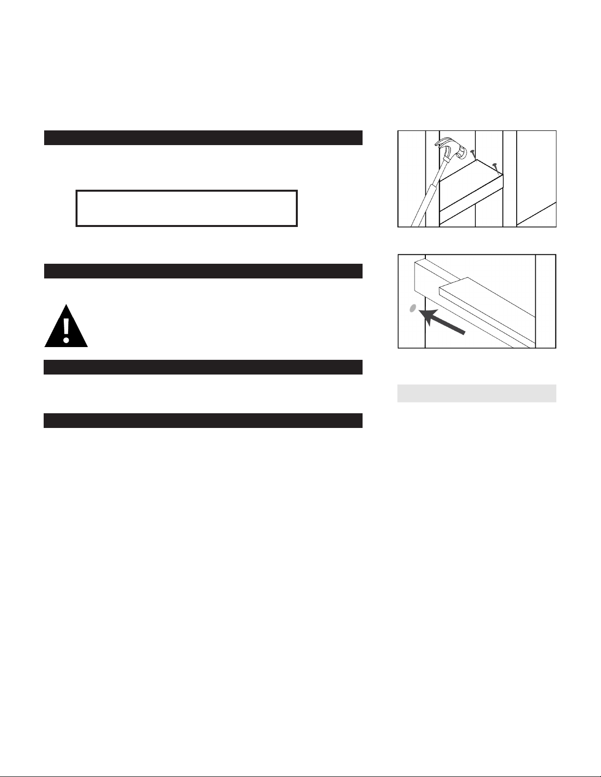
TURN POWER OFF AT SERVICE ENTRANCE.
Then, begin installation by removing the screws at the top
and bottom of electrical raceway to access the inside.
A black and white pigtail are provided for electrical
hook-up located near bottom of raceway. Connect supply
wires to these pigtails.
DO NOT attempt to connect to any other location inside
the electrical raceway. Doing so will cause the electrical
features to malfunction.
A green ground wire is provided and secured with a star
washer to the back of the electrical channel. Connect
your own ground to that location or attach to the location
opposite the existing ground and add your own star
washer.
Locate and remove the knockout at the top of the raceway
and install a 3/8” Romex connector in its location.
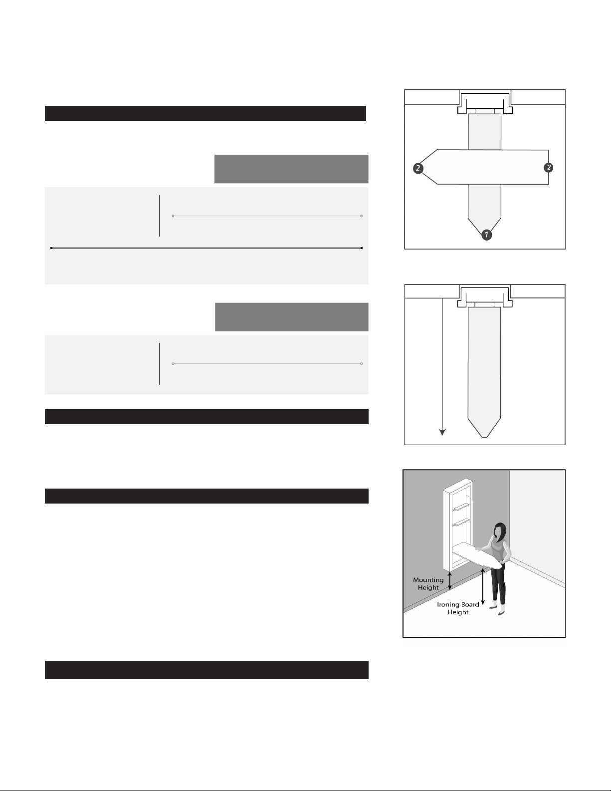
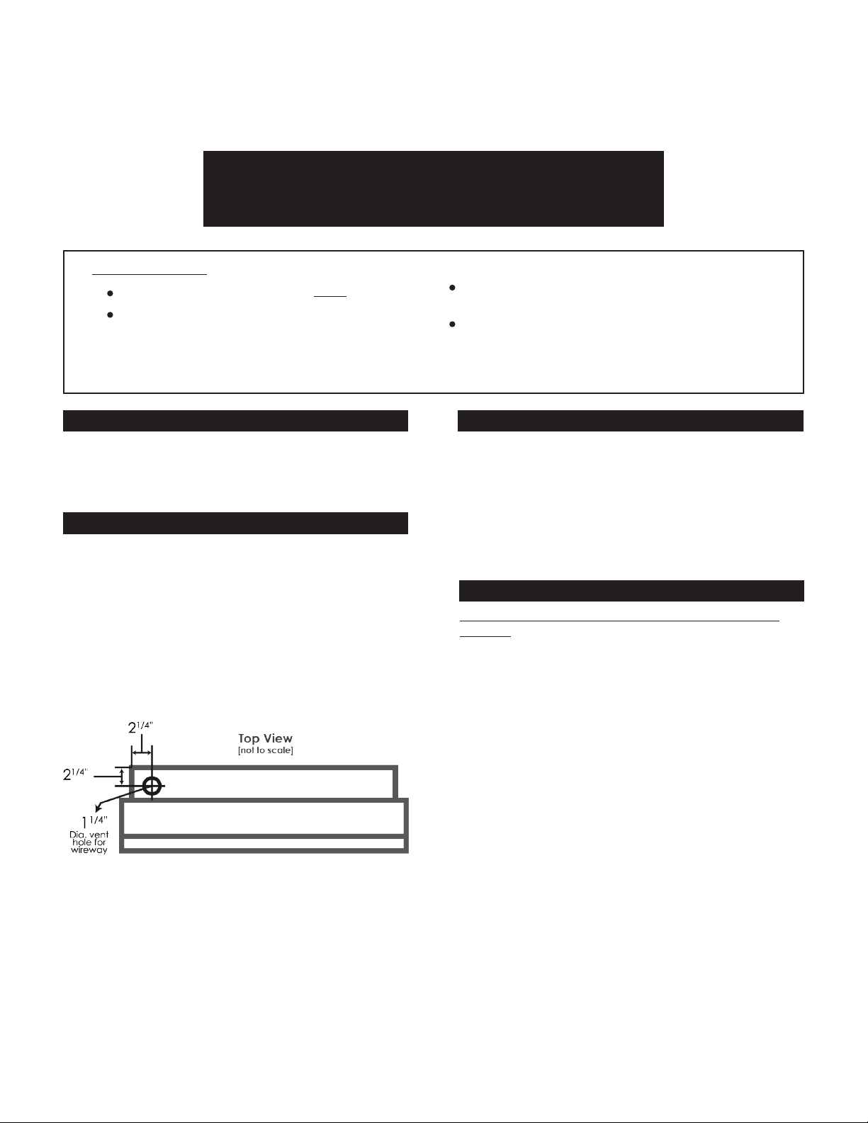
If surface mounting, a vent hole will need be made
through the back side of the cabinet, 24 1/2” down from
top of cabinet, and 2 13/16” from cabinet le side.
Verify that there is ample supply wire (48” is
recommended) available to run from the top of the ironing
center to the location of the provided black and white
pigtails.
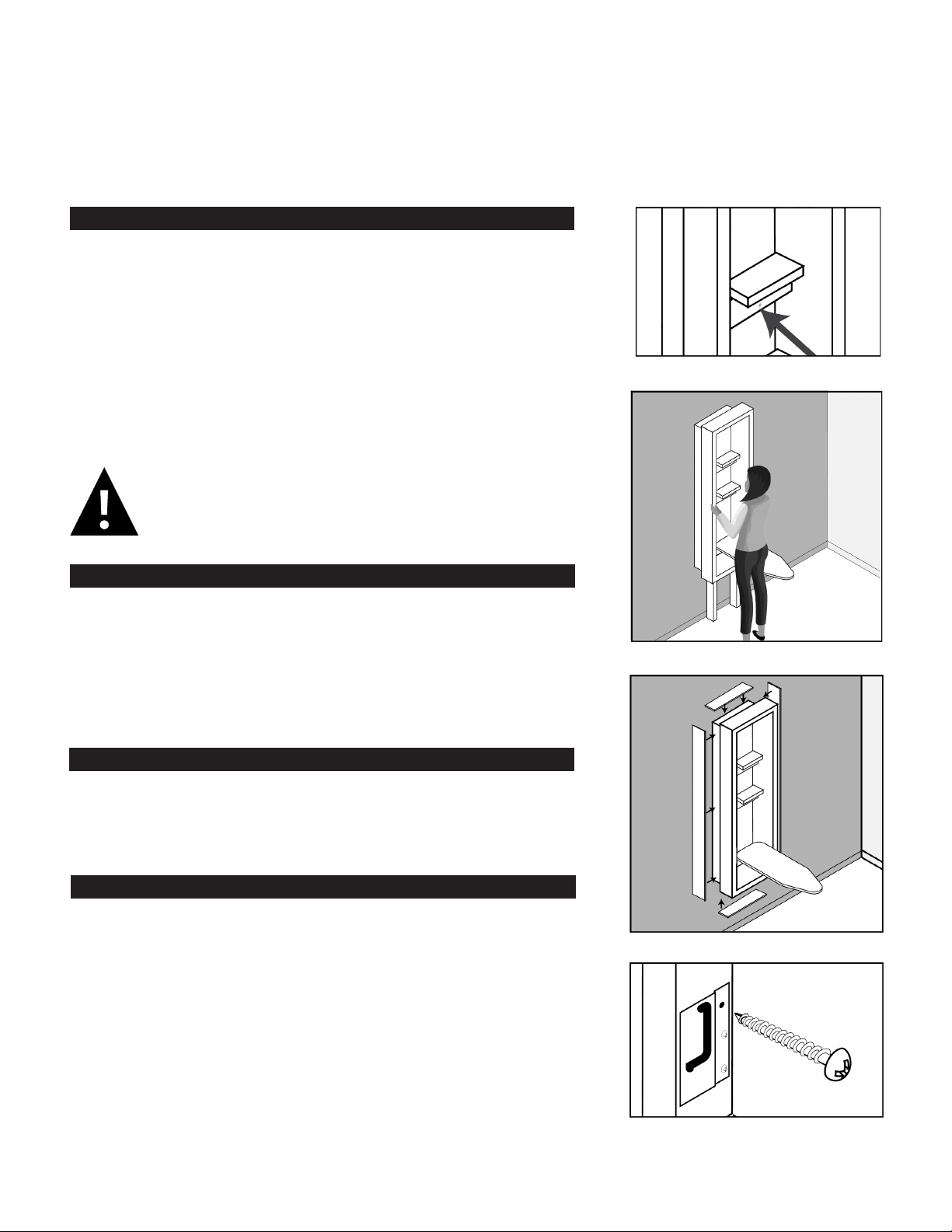
Begin to place the ironing center into its location
(supported by cleat if recessed or with the 2 x 4 braces if
surface mounted) while feeding supply wire through the
designated vent hole.
Return to Swivel or Non-Swivel instructions to complete
installation of unit to the wall. When finished, return to
complete final steps here.
INSTALLATION COMPLETE!
ELECTRICAL | PG. 7

Still have questions?
We’re here to help!
1-800-536-9495
support@ironaway.com
M-F 8am-4:30pm CST
001072 6/21
Other manuals for UD-42
3
This manual suits for next models
9
Table of contents
Other Iron-A-Way Ironing Center manuals