IS5 COMMUNICATIONS IEC61850 User manual

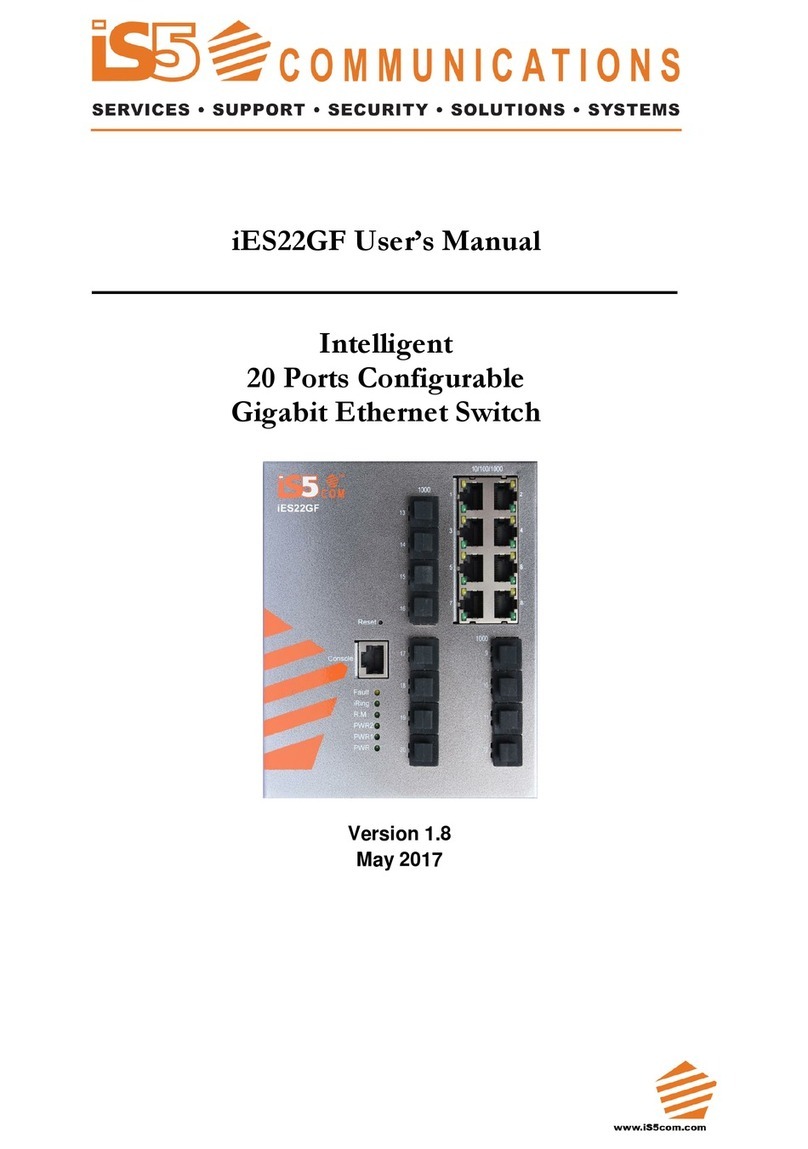
iES22GF User’s Manual
UM-iES22GF-1.92.1-EN.docx
COPYRIGHT NOTICE
© 2021 iS5 Communications Inc. All rights reserved.
No part of this publication may be reproduced in any form without the prior written consent of iS5
Communications Inc. (iS5).
TRADEMARKS
iS5Com is a registered trademark of iS5. All other trademarks belong to their respective owners.
REGULATORY COMPLIANCE STATEMENT
Product(s) associated with this publication complies/comply with all applicable regulations. For more
details, refer to the Technical Specifications section.
WARRANTY
iS5 warrants that all products are free from defects in material and workmanship for a specified warranty
period from the invoice date (5 years for most products). iS5 will repair or replace products found to be
defective within this warranty period including shipping costs. This warranty does not cover product
modifications or repairs done by persons other than iS5-approved personnel, and this warranty does not
apply to products that are misused, abused, improperly installed, or damaged by accident.
Refer to the Technical Specifications section for the actual warranty period(s) of the product(s) associated
with this publication.
DISCLAIMER
Information in this publication is intended to be accurate. iS5 shall not be responsible for its use or
infringements on third-parties because of the use of this publication. There may occasionally be
unintentional errors on this publication. iS5 reserves the right to revise the contents of this publication
without notice.
CONTACT INFORMATION
iS5 Communications Inc.
5895 Ambler Drive, Mississauga, Ontario, L4W 5B7
Tel: + 905-670-0004 // Fax: + 289-401-5206
Website: www.iS5Com.com
Technical Support
E-mail: support@iS5Com.com
Sales Contact
E-mail: [email protected]m

iES22GF User’s Manual
UM-iES22GF-1.92.1-EN.docx Page i
Table of Contents
FCC Statement and Cautions ................................................................... 1
Federal Communications Commission Radio Frequency Interference Statement ................................ 1
Caution: LASER...................................................................................................................................... 1
Caution: Service .................................................................................................................................... 1
Caution: Physical Access....................................................................................................................... 1
1. Getting Started .................................................................................. 2
1.1 About iES22GF........................................................................................................................... 2
1.2 References ................................................................................................................................ 3
1.3 Acronyms.................................................................................................................................. 3
1.4 Software Features...................................................................................................................... 7
1.5 Hardware Specifications ........................................................................................................... 7
2. Hardware Overview ........................................................................... 8
2.1 Front Panel................................................................................................................................ 8
2.2 Front Panel LED......................................................................................................................... 9
2.3 Bottom View of Panel ................................................................................................................ 9
2.4 Rear Panel ............................................................................................................................... 11
2.5 Side Panel ............................................................................................................................... 11
3. Hardware Installation........................................................................12
3.1 Installing the Switch on DIN-Rail ............................................................................................. 12
3.1.1 Mounting on DIN-Rail.............................................................................................................. 12
3.2 Wall Mount Installation ........................................................................................................... 13
3.2.1 Mounting iES22GF on a Wall or Panel..................................................................................... 13
3.3 Connection.............................................................................................................................. 14
3.3.1 Ethernet Cables ...................................................................................................................... 14
3.3.2 Pin Assignments...................................................................................................................... 14
3.3.3 SFP .......................................................................................................................................... 15
3.4 Console Cable ........................................................................................................................ 16
4. Redundancy overview .......................................................................17
4.1 STP/RSTP/MSTP ...................................................................................................................... 17
4.1.1 STP/RSTP................................................................................................................................. 17
4.1.2 MSTP ....................................................................................................................................... 17
4.2 Fast Recovery.......................................................................................................................... 17
5. Web Management.............................................................................18
5.1 Basic Setting............................................................................................................................ 20
5.1.1 Basic Setting (System Information Configuration)................................................................... 20
5.1.2 Banner..................................................................................................................................... 21
5.1.3 Admin Password..................................................................................................................... 21
5.1.4 Guest Password ...................................................................................................................... 22

iES22GF User’s Manual
UM-iES22GF-1.92.1-EN.docx Page ii
5.1.5 Authentication Method............................................................................................................ 22
5.1.6 Auto Logout............................................................................................................................. 23
5.1.7 IP Setting................................................................................................................................. 23
5.1.8 IPv6 Setting ............................................................................................................................. 24
5.1.9 SNTP Configuration (only for SNTP Version) .......................................................................... 25
5.1.10 NTP Configuration (only for NTP Version) .............................................................................. 26
5.1.11 Daylight Saving Time .............................................................................................................. 27
5.1.12 Switch Time Configuration...................................................................................................... 28
5.1.13 HTTPS...................................................................................................................................... 28
5.1.14 SSH.......................................................................................................................................... 29
5.1.15 Telnet ...................................................................................................................................... 29
5.1.16 LLDP........................................................................................................................................ 30
5.1.17 Modbus TCP............................................................................................................................ 33
5.1.18 Backup .................................................................................................................................... 33
5.1.19 Restore.................................................................................................................................... 34
5.1.20 Firmware Update .................................................................................................................... 34
5.2 DHCP Server/Relay................................................................................................................. 36
5.2.1 Setting ..................................................................................................................................... 36
5.2.2 DHCP Dynamic Client List ...................................................................................................... 37
5.2.3 DHCP Static Client List............................................................................................................ 37
5.2.4 DHCP Relay Agent .................................................................................................................. 38
5.3 Port Setting.............................................................................................................................. 40
5.3.1 Port Control ............................................................................................................................ 40
5.3.2 Port Trunk ............................................................................................................................... 42
5.3.3 Loop Protection ....................................................................................................................... 47
5.4 Redundancy ............................................................................................................................ 48
5.4.1 iRing........................................................................................................................................ 48
5.4.2 iChain...................................................................................................................................... 49
5.4.3 iBridge .................................................................................................................................... 49
5.4.4 RSTP ........................................................................................................................................ 50
5.4.5 MSTP ....................................................................................................................................... 54
5.4.6 MRP......................................................................................................................................... 62
5.4.7 Fast Recovery.......................................................................................................................... 62
5.4.8 Dual Port Recovery ................................................................................................................. 64
5.5 VLAN....................................................................................................................................... 66
5.5.1 VLAN Membership ................................................................................................................. 66
5.5.2 Ports Configuration ................................................................................................................ 67
5.5.3 Private VLAN .......................................................................................................................... 76
5.6 SNMP....................................................................................................................................... 78
5.6.1 SNMP System Configurations ................................................................................................. 78
5.6.2 SNMP Community Configurations.......................................................................................... 80
5.6.3 SNMP User Configurations..................................................................................................... 81
5.6.4 SNMP Group Configurations.................................................................................................. 83
5.6.5 SNMP View Configurations .................................................................................................... 83
5.6.6 SNMP Access Configurations ................................................................................................. 84
5.7 Traffic Prioritization................................................................................................................. 86
5.7.1 Storm Control.......................................................................................................................... 86
5.7.2 Port Classification................................................................................................................... 86
5.7.3 Port Tag Remarking................................................................................................................ 88

iES22GF User’s Manual
UM-iES22GF-1.92.1-EN.docx Page iii
5.7.4 Port DSCP ............................................................................................................................... 90
5.7.5 Port Policing ........................................................................................................................... 91
5.7.6 Queue Policing ....................................................................................................................... 92
5.7.7 Port Schedulers ...................................................................................................................... 92
5.7.8 Port Shaping ........................................................................................................................... 93
5.7.9 DSCP-Based QoS..................................................................................................................... 96
5.7.10 DSCP Translation .................................................................................................................... 97
5.7.11 DSCP Classification................................................................................................................. 98
5.7.12 QoS Control List ..................................................................................................................... 99
5.7.13 QoS Statistics ........................................................................................................................ 101
5.7.14 QCL Status ............................................................................................................................ 103
5.8 Multicast................................................................................................................................ 105
5.8.1 IGMP Snooping Basic Configuration .................................................................................... 105
5.8.2 IGMP Snooping VLAN Configurations .................................................................................. 106
5.8.3 IGMP Snooping Status .......................................................................................................... 107
5.8.4 IGMP Snooping Group Information ...................................................................................... 108
5.9 Security ................................................................................................................................. 109
5.9.1 Remote Control Security Configuration ................................................................................ 109
5.9.2 Device Binding...................................................................................................................... 109
5.9.3 ACL ....................................................................................................................................... 115
5.9.4 AAA....................................................................................................................................... 129
5.9.5 NAS (802.1x) ......................................................................................................................... 138
5.10 Warning ................................................................................................................................ 150
5.10.1 Fault Alarm............................................................................................................................ 150
5.10.2 System Warning.................................................................................................................... 150
5.11 Monitor and Diagnostic......................................................................................................... 153
5.11.1 MAC Table............................................................................................................................ 153
5.11.2 Port Statistic .......................................................................................................................... 156
5.11.3 Port Monitoring ..................................................................................................................... 158
5.11.4 System Log Information ........................................................................................................ 159
5.11.5 VeriPHY Cable Diagnostics .................................................................................................. 159
5.11.7 SFP Monitor........................................................................................................................... 161
5.11.8 Ping....................................................................................................................................... 161
5.11.9 Ping6 ..................................................................................................................................... 162
5.12 Factory Defaults .................................................................................................................... 162
5.13 System Reboot...................................................................................................................... 163
6. CLI Management............................................................................ 164
6.1 Command Line Interface Setup............................................................................................. 164
6.1.1 CLI Management by RS-232 Serial Console (115200, 8, none, 1, none) ................................ 164
6.1.2 CLI Management by Telnet................................................................................................... 166
6.1.3 Command Groups................................................................................................................. 167
7. Appendix A: iES22GF Modbus Information ......................................... 182
Table of Figures
Figure 1 –Rear Panel........................................................................................................................... 11
Figure 2 –Side Panel ........................................................................................................................... 11

iES22GF User’s Manual
UM-iES22GF-1.92.1-EN.docx Page iv
Figure 3 - DIN-Rail Bracket .................................................................................................................. 12
Figure 4 - Switch Mounted on DIN-Rail................................................................................................ 12
Figure 5 - Brackets Mounted on Side of Switch.................................................................................... 13
Figure 6 - Brackets Mounted on back of Switch................................................................................... 13
Figure 7 –SFPs .................................................................................................................................... 15
Figure 8 –Console Cable Connection................................................................................................. 16
Figure 9 –Switch’s IP Address Screen................................................................................................. 18
Figure 10 –Login Screen ..................................................................................................................... 18
Figure 11 –Main Interface or System Information tab ......................................................................... 19
Figure 12 –System Information Configuration .................................................................................... 20
Figure 13 –System Banner Configuration ........................................................................................... 21
Figure 14 - System Password ............................................................................................................... 21
Figure 15 –Guest Password Configuration ......................................................................................... 22
Figure 16 - Authentication Method Configuration ............................................................................... 22
Figure 17 - Auto Logout Configuration ................................................................................................ 23
Figure 18 - IP Configuration ................................................................................................................ 23
Figure 19 –IPv6 Configuration ............................................................................................................ 24
Figure 20 - SNTP Configuration ........................................................................................................... 25
Figure 21 - NTP Configuration ............................................................................................................. 26
Figure 22 - Time Zone Configuration................................................................................................... 27
Figure 23 –Switch Time Configuration................................................................................................ 28
Figure 24 - HTTPS Configuration ......................................................................................................... 28
Figure 25 - SSH Configuration ............................................................................................................. 29
Figure 26 - Telnet Configuration ......................................................................................................... 29
Figure 27 - LLDP Configuration ........................................................................................................... 30
Figure 28 - LLDP Neighbor Information............................................................................................... 31
Figure 29 - LLDP Global Counters ....................................................................................................... 32
Figure 30 - MODBUS Configuration ..................................................................................................... 33
Figure 31 –Configuration Save ........................................................................................................... 34
Figure 32 –Configuration Upload ....................................................................................................... 34
Figure 33 –Software Upload................................................................................................................ 35
Figure 34 –DHCP Server Configuration .............................................................................................. 36
Figure 35 –DHCP Dynamic Client List ................................................................................................ 37
Figure 36 –DHCP Static Client List ...................................................................................................... 37
Figure 37 –DHCP Relay Configuration................................................................................................ 38
Figure 38 –DHCP Relay Statistics ........................................................................................................ 39
Figure 39 –Client Statistics.................................................................................................................. 39
Figure 40 –Port Configuration ............................................................................................................ 40
Figure 41 - Aggregation Mode Configuration ..................................................................................... 42
Figure 42 - Aggregation Group Configuration .................................................................................... 42
Figure 43 –LACP Port Configuration................................................................................................... 43
Figure 44 –LACP System Status........................................................................................................... 44
Figure 45 - LACP Status ....................................................................................................................... 45
Figure 46 - LACP Statistics ................................................................................................................... 46
Figure 47 –Loop Protection................................................................................................................. 47
Figure 48 - Port Configuration ............................................................................................................. 47
Figure 49 - iRing Configuration ........................................................................................................... 48
Figure 50 - iChain Configuration ......................................................................................................... 49
Figure 51 –iBridge .............................................................................................................................. 49
Figure 52 - RSTP Bridge Setting interface............................................................................................ 50
Figure 53 - RSTP Port Setting ............................................................................................................... 51
Figure 54 - RSTP Bridge Status............................................................................................................. 52
Figure 55 - RSTP Port Status ................................................................................................................. 53
Figure 56 - STP Bridge Configuration .................................................................................................. 54
Figure 57 - MSTI Configuration............................................................................................................ 55
Figure 58 - MSTI Configuration............................................................................................................ 56
Figure 59 –STP MSTI Port Configuration ............................................................................................. 57
Figure 60 –MSTI Port Configuration.................................................................................................... 59
Figure 61 - STP Bridges ....................................................................................................................... 60
iES22GF User’s Manual
UM-iES22GF-1.92.1-EN.docx Page v
Figure 62 - STP Port Status ................................................................................................................... 60
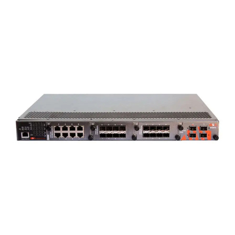
Figure 63 - STP Statistics ...................................................................................................................... 61
Figure 64 - MRP ................................................................................................................................... 62
Figure 65 - Fast Recovery .................................................................................................................... 63
Figure 66 –Dual Port Recovery ........................................................................................................... 65
Figure 67 - VLAN Membership Configuration ..................................................................................... 66
Figure 68 - VLAN Port Configuration ................................................................................................... 67
Figure 69 - VLAN Membership Configuration ..................................................................................... 72
Figure 70 - VLAN Port Configuration ................................................................................................... 72
Figure 71 - VLAN Membership Configuration ..................................................................................... 73
Figure 72 - VLAN Port Configuration ................................................................................................... 73
Figure 73 - VLAN Membership Configuration ..................................................................................... 74
Figure 74 - VLAN Port Configuration ................................................................................................... 74
Figure 75 - VLAN Membership Configuration ..................................................................................... 75
Figure 76 - VLAN Port Configuration ................................................................................................... 75
Figure 77 –IP Configuration ................................................................................................................ 75
Figure 78 –Private VLAN Membership Configuration ........................................................................ 76
Figure 79 –Port Isolation Configuration .............................................................................................. 77
Figure 80 –SNMP System Configuration ............................................................................................. 78
Figure 81 –SNMP Trap Configuration ................................................................................................. 79
Figure 82 –SNMPv3 Community Configuration .................................................................................. 80
Figure 83 –SNMPv3 User Configuration.............................................................................................. 81
Figure 84 –SNMPv3 Group Configuration........................................................................................... 83
Figure 85 –SNMPv3 View Configuration............................................................................................. 83
Figure 86 –SNMPv3 Access Configuration.......................................................................................... 84
Figure 87 - QoS Port Storm Control ..................................................................................................... 86
Figure 88 - QoS Ingress Port Classification ......................................................................................... 87
Figure 89 - QoS Egress Port Tag Remarking ....................................................................................... 89
Figure 90 - QoS Port DSCP Configuration............................................................................................ 90
Figure 91 - QoS Ingress Port Policers .................................................................................................. 91
Figure 92 - QoS Ingress Queue Policers.............................................................................................. 92
Figure 93 - QoS Egress Port Policers ................................................................................................... 92
Figure 94 - QoS Egress Port Shapers ................................................................................................... 93
Figure 95 - QoS Ingress Port Scheduler and Shapers Port 1- Strict Priority......................................... 93
Figure 96 - QoS Egress Port Scheduler and Shapers Port 1 –Scheduler Mode Weighted .................. 94
Figure 97 - QoS DSCP-Based QoS Ingress Classification..................................................................... 96
Figure 98 - DSCP Translation............................................................................................................... 97
Figure 99 - DSCP Classification ........................................................................................................... 98
Figure 100 - QoS Control List Configuration........................................................................................ 99
Figure 101 - QoS Statistics ................................................................................................................. 101
Figure 102 - Detailed Port Statistics Port 7 ......................................................................................... 102
Figure 103 - QoS Control List Status .................................................................................................. 103
Figure 104 - IGMP Snooping Configuration....................................................................................... 105
Figure 105 - IGMP Snooping VLAN Configuration............................................................................. 106
Figure 106 - IGMP Snooping Status ................................................................................................... 107
Figure 107 - IGMP Snooping Group Information ............................................................................... 108
Figure 108 - Remote Control Security Configuration......................................................................... 109
Figure 109 - Device Binding .............................................................................................................. 109
Figure 110 - Alias IP Address ............................................................................................................ 111
Figure 111 - Alive Check ................................................................................................................... 111
Figure 112 - DDoS Prevention ........................................................................................................... 112
Figure 113 - Device Description ........................................................................................................ 113
Figure 114 - Steam Check.................................................................................................................. 114
Figure 115 - ACL Ports Configuration................................................................................................ 115
Figure 116 - ACL Rate Limiter Configuration..................................................................................... 116
Figure 117 - ACL Control List Configuration ..................................................................................... 117
Figure 118 - Default ACE Configuration ............................................................................................ 117
Figure 119 - ACE Configuration ........................................................................................................ 118
Figure 120 - MAC Parameters ........................................................................................................... 119

iES22GF User’s Manual
UM-iES22GF-1.92.1-EN.docx Page vi
Figure 121 - VLAN Parameters (default values or with Filter “Specific”) .......................................... 119
Figure 122 - IP Parameters ................................................................................................................ 120
Figure 123 - ARP Parameters ............................................................................................................. 122
Figure 124 - ICMP Parameters........................................................................................................... 124
Figure 125 - TCP / UDP Parameters................................................................................................... 125
Figure 126 - Ethernet Type Parameters............................................................................................. 127
Figure 127 - ACL Status ..................................................................................................................... 128
Figure 128 - Common Server Configuration ..................................................................................... 129
Figure 129 - RADIUS Authentication Server Configuration................................................................ 130
Figure 130 - RADIUS Accounting Server Configuration..................................................................... 130
Figure 131 - TACACS+ Authentication Server Configuration ............................................................ 131
Figure 132 - Radius Authentication Server Status Configuration ....................................................... 131
Figure 133 - Radius Accounting Server Status Configuration ............................................................ 132
Figure 134 - Radius Authentication Statistics for Server #1 ............................................................... 133
Figure 135 - Radius Accounting Statistics for Server #1 .................................................................... 135
Figure 136 - Network Access Server Configuration .......................................................................... 139
Figure 137 - Network Access Server Port Configuration ................................................................... 141
Figure 138 - Network Access Server Switch Status ............................................................................ 143
Figure 139 - NAT Statistics Admin State Force Authorized ................................................................ 144
Figure 140 –EAPOL Counters Admin State Force Authorized........................................................... 145
Figure 141 - NAT Statistics Admin MAC-based Auth. ........................................................................ 146
Figure 142 - Last Supplicant/ Client Info Admin State MAC-based Auth. .......................................... 148
Figure 143 - Last Supplicant/ Client Info Admin State 802.1X-based................................................. 148
Figure 144 –Selected Counters / Attached Clients ........................................................................... 149
Figure 145 - Fault Alarm .................................................................................................................... 150
Figure 146 - System Log Configuration ............................................................................................. 150
Figure 147 - SMTP Settings ................................................................................................................ 151
Figure 148 - System Warning - Event Selection................................................................................. 152
Figure 149 - MAC Address Table Configuration ............................................................................... 153
Figure 150 - MAC Address Table ...................................................................................................... 155
Figure 151 - Port Statistics Overview................................................................................................. 156
Figure 152 - Detailed Post Statistics................................................................................................... 157
Figure 153 - Mirror Configuration ..................................................................................................... 158
Figure 154 - System Log Information ................................................................................................. 159
Figure 155 - VeriPHY Cable Diagnostics ........................................................................................... 160
Figure 156 - SFP Monitor ................................................................................................................... 161
Figure 157 - ICMP Ping...................................................................................................................... 161
Figure 158 –ICMPv6 Ping ................................................................................................................. 162
Figure 159 - Factory Defaults............................................................................................................. 163
Figure 160 - System Reboot - Restart Device..................................................................................... 163
Figure 161 –Tera Term VT, Setup Menu ........................................................................................... 164
Figure 162 –Tera Term VT, Serial port setup .................................................................................... 164
Figure 163 - iES22GF Command Line Interface - Tera Term VT ........................................................ 165
Figure 164 - Telnet Command Prompt .............................................................................................. 166
Figure 165 - iES22GF Command Line Interface - Telnet.................................................................... 166
Figure 166 - Command Groups Printout............................................................................................ 167
Table of Tables
Table 1 –Port Numbering.................................................................................................................... 14
Table 2 –10/100 Base-T(X) Line Pin Assignments ............................................................................... 14
Table 3 –1000 Base-T Line Pin Assignments ....................................................................................... 14
Table 4 –10/100 Base-T(X) MDI/MDI- X Pin Assignments................................................................... 15
Table 5 –1000 Base-T MDI/MDI- X Pin Assignments ........................................................................... 15
Table 6 –Signals and Pinouts from Console Port RJ-45 to DB-9 Serial Port Adapter............................ 16

iES22GF User’s Manual
UM-iES22GF-1.92.1-EN.docx Page 1
© 2021 IS5 COMMUNICATIONS INC. ALL RIGHTS RESERVED
FCC STATEMENT AND CAUTIONS
Federal Communications Commission Radio Frequency
Interference Statement
This equipment has been tested and found to comply with the limits for a Class A digital device pursuant to
Part 15 of the FCC Rules. These limits are designed to provide reasonable protection against harmful
interference when the equipment is operated in a commercial environment. This equipment cangenerate,
use, and radiate radio frequency energy. If not installed and used in accordance with the instruction manual,
may cause harmful interference to radio communications. Operation of this equipment in a residential area
is likely to cause harmful interference in which case the user will at his/her own expense, be required to
correct the interference.
This is a class A product. In a domestic environment, this product may cause radio interference in which case
the user may be required to take adequate measures.
Caution: LASER
This product contains a laser system and is classified as a CLASS 1 LASER PRODUCT. Use of controls or
adjustments or performance of procedures other than those specified herein may result in hazardous
radiation exposure.
Caution: Service
This product contains no user-serviceable parts. Attempted service by unauthorized personnel shall render
all warranties null and void.
Changes or modifications not expressly approved by iS5 Communications Inc. could invalidate specifications,
test results, and agency approvals, and void the user's authority to operate the equipment.
Caution: Physical Access
This product should be installed in a restricted access location. Access should only be gained by
qualified service personnel or users who have been instructed on the reasons for the restrictions
applied at the location, and any precautions that have been taken. Access must only be via the use of a
tool or lock and key, or other means of security, and is controlled by the authority responsible for the
location.

iES22GF User’s Manual
UM-iES22GF-1.92.1-EN.docx Page 2
© 2021 IS5 COMMUNICATIONS INC. ALL RIGHTS RESERVED
1. GETTING STARTED
1.1 About iES22GF
The iES22GF is an intelligent managed 20 port Gigabit Ethernet switch with 8 x 10/100/1000Base-T(X)
RJ45 ports and up to 12 x 100/1000Base-X SFP ports.
The switch is IEC 61850-3 and IEEE 1613 compliant.
The iES22GF provides redundancy support through functions such as STP/RSTP/MSTP assuring
protection of all mission critical network applications. iES22GF can be managed via the Web UI,
iManage Software Suite, Telnet, and Console (CLI) / SSH v2.
The switch is made of IP-40 galvanized steel and has a wide operating temperature range from -40°C to
+85°C, which is suitable for the harshest of environments without the use of fans.

iES22GF User’s Manual
UM-iES22GF-1.92.1-EN.docx Page 3
© 2021 IS5 COMMUNICATIONS INC. ALL RIGHTS RESERVED
1.2 References
[1] Cisco.com, Configuring QoS
https://www.cisco.com/c/en/us/td/docs/switches/metro/me1200/gui/guide/b_ME1200_Web_GUI
_book/b_ME1200_Web_GUI_book_chapter_011010.pdf Online, Accessed on Mar 26, 2019
[2] Network Working Group, RFC 3768, Virtual Router Redundancy Protocol (VRRP),
https://tools.ietf.org/html/rfc3768#section-5.3.6 Online, Accessed on Mar 29, 2019
[3] Network Working Group, RFC 4668, RADIUS Authentication Client MIB for IPv6,
https://tools.ietf.org/html/rfc4668 , Online, Accessed on Apr 3, 2019
[4] Network Working Group, RFC 4670, RADIUS Accounting Client MIB for IPv6,
https://tools.ietf.org/html/rfc4670 , Online, Accessed on Apr 3, 2019
[5] Network Working Group, RFC 3164, The BSD syslog Protocol, https://tools.ietf.org/html/rfc3748 , Online,
Accessed on Apr 3, 2019
[6] Oracle.com, STP Administration Guide, IST, CIST, AND CST, https://docs.oracle.com/cd/E19934-
01/html/E21706/z40037c31414269.html#scrolltoc, Online, Accessed on Apr 3, 2019
[7] Stack Overflow, Maximum size of ICMP IPv6 packet,
https://stackoverflow.com/questions/15434362/maximum-size-of-icmp-ipv6-packet
[8] Cisco.com, Cisco APIC and QoS
https://www.cisco.com/c/en/us/td/docs/switches/datacenter/aci/apic/sw/kb/Cisco-APIC-and-
QoS.html#id_34903 , Online, Accessed on Apr 17, 2019
[9] Cisco.com, Chapter: Configuring QoS, QoS Components,
https://www.cisco.com/c/en/us/td/docs/switches/lan/catalyst9400/software/release/16-
6/configuration_guide/qos/b_166_qos_9400_cg/b_166_qos_9400_cg_chapter_01.html Online,
Accessed on Apr 17, 2019
[10] Cisco.com, Configuring Traffic Storm Control,
https://www.cisco.com/c/en/us/td/docs/switches/datacenter/sw/4_1/nx-
os/security/configuration/guide/sec_nx-os-cfg/sec_storm.pdf Online, Accessed on May 1, 2019
1.3 Acronyms
The following table shows all acronyms used in this document.
Acronym
Explanation
ACE
Access Control Entry
ACL
Access Control List
AF
Assured Forwarding
ARP
Address Resolution Protocol
BPDU
Bridge Protocol Data Unit
CIST
Common and Internal Spanning Tree
CLI
Command Line Interface
DCHP
Dynamic Host Configuration Protocol
DDM
Digital Diagnostic Monitoring

iES22GF User’s Manual
UM-iES22GF-1.92.1-EN.docx Page 4
© 2021 IS5 COMMUNICATIONS INC. ALL RIGHTS RESERVED
Acronym
Explanation
DEI
Discard Eligibility (subfield in an IEEE 802.1Q frame header)
DNS
Domain Name Server
DSAP
Destination Service Access Point
DSCP
Differentiated Services Code Point
DP
Drop Precedence
EAP
Extensible Authentication Protocol
EAPOL
EAP Over LAN
HLN
Hardware Address Length
HRD
hardware address space (i.e. ARP hardware address type (ar$hrd)))
HSR
High-availability Seamless Redundancy
HTTPS
Hyper Text Transfer Protocol Secure or HTTP over SSL
ICMP
Internet Control Message Protocol
IGMP
Internet Group Management Protocol
IP
Internet Protocol (IP)
IPMC(v4)
IPv4 MultiCast
LAG
Link Aggregation Group
LACP
Link Aggregation Control Protocol
LLDP
Link Layer Discovery Protocol
LLDP- MED
LLDP - Media Endpoint Discovery
LLDPDU
LLDP Data Unit
MIB
Management Information Base
MRP
Media Redundancy Protocol
MSTI
Multiple Spanning Tree Instances
MSTP
Multiple Spanning Tree Protocol
NTP
Network Time Protocol
OID
Object Identifier

iES22GF User’s Manual
UM-iES22GF-1.92.1-EN.docx Page 5
© 2021 IS5 COMMUNICATIONS INC. ALL RIGHTS RESERVED
Acronym
Explanation
OUI
Organizationally Unique Identifier (In Linux)
PDU
Protocol Data Unit
PID
Process Identifier
P2P
Point-To-Point (link)
PSH
Push Function (a value for the ACE)
PWR
Power
QCE
QoS Control Entry
QCL
QoS Control List
QoS
Quality of Service
RARP
Reverse Address Resolution Protocol (Reverse ARP)
RIP
Routing Information Protocol
RMON
Remote Monitoring
RSTP
Rapid Spanning Tree Protocol
SIP
Source IP
SMAC
Source MAC Address
SNMP
Simple Network Management Protocol
SNTP
Simple Network Time Protocol
SSAP
Source Service Access Point
SSH
Secure Shel
TACACS
Terminal Access Controller Access Control System
TCN
Topology Change Notification
TCP
Transmission Control Protocol
THA
target Hardware Address
TLV
Type-Length-Value
TPID
Tag protocol identifier
TTL
Time to live

iES22GF User’s Manual
UM-iES22GF-1.92.1-EN.docx Page 6
© 2021 IS5 COMMUNICATIONS INC. ALL RIGHTS RESERVED
Acronym
Explanation
SSH
Secure Shell
UDP
User Datagram Protocol
URG
Urgent Pointer Field Significant (an ACE value)
USM
User-based Security Model
UTC
Coordinated Universal Time
VACM
View based Access Control Model
VCXO
Voltage Controlled Crystal Oscillator
VID
VLAN ID

iES22GF User’s Manual
UM-iES22GF-1.92.1-EN.docx Page 7
© 2021 IS5 COMMUNICATIONS INC. ALL RIGHTS RESERVED
1.4 Software Features
•Web or CLI based Management (Console or Telnet / SSH v2)
•DHCP Server / Relay
•VLAN (802.1Q) for segregating and securing network traffic
•Supports SNMPv1/v2/v3
•Traffic Prioritization—Storm Control and Quality of Service (QoS) including DSCP-Based QoS Ingress
Port Classification
•Multicast traffic—IGMP Snooping (IGMP v1/v2 / v3) and unregistered IPMCv4 Flooding
•Warnings (Syslog and SMTP) and Fault Alarm (power failure)
•Monitoring and Diagnostics—MAC Table and Port Statistics (ports monitoring including for SFP ports,
system information, issuing PING packets for troubleshooting IP connectivity issues)
•SNTP for synchronizing of clocks over network
•Supports standard IEC 62439-2 MRP (Media Redundancy Protocol) functionality
1.5 Hardware Specifications
Description
Specification
10/100/1000 Base-T(X) RJ45
Ports Auto MDI/MDIX
8
100/1000Base-X SFP Ports
Up to 12
RS-232 Serial Console Port
RS-232 in RJ45 connector with console cable: 115200 bps, 8, N, 1
Warning / Monitoring System
Relay output for fault event alarming
2 alarm warning methods for system events supported:
•SYSLOG with server / client structure; recording and viewing
events in the System Event Log
•SMTP for notification via email
Event selection per port
Alarm
Relay output to carry capacity of 1 A at 24 VDC
Physical Characteristics
Enclosure
IP-40 Galvanized Steel
Dimensions (W x D x H)
133.7 (W) x 157.5 (D) x 154.1 (H) mm (5.27 x 6.20 x 6.07 inches)
Weight (g)
~3500 g
Power
Input Power
Redundant Power Supplies: Dual DC Inputs 9-36VDC, Dual DC
Inputs 36-75VDC, or Dual Input 110-370VDC or 90-264VAC
Power Consumption (Typ.)
18 Watts
Overload Current Protection
Present
Reverse Polarity Protection
Internal

iES22GF User’s Manual
UM-iES22GF-1.92.1-EN.docx Page 8
© 2021 IS5 COMMUNICATIONS INC. ALL RIGHTS RESERVED
2. HARDWARE OVERVIEW
2.1 Front Panel
iS5 provides the following modules:
Description Specification
10/100/1000 Base-T(X) RJ45
Ports Auto MDI/MDIX
8
100/1000Base-X SFP Ports Up to 12
RS-232 Serial Console Port RS-232 with
RJ45 connector with console cable: 115200 bps, 8, N, 1
1Reset button. Push the button 3 seconds for reset; 5 seconds for factory default.
2LED for PWR. When the PWR UP, the green led will be light on
3LED for PWR1
4LED for PWR2
5LED for R.M (Ring master). When the LED light on, it means that the switch is the ring
master of Ring.LED for Ring. When the led light on, it means the Ring is activated.
6LED for Ring. When the led light on, it means the iRing is activated.
7LED for Fault. When the light on, it means Power failure or Port down/fail.
8Console port (RJ-45)
9100/1000 Base-X SFP
10 LED for Ethernet ports link status.
11 LED for Ethernet ports speed status
12 10/100/1000Base-T(X) ports
13 LED for SFP ports link status.
14 100/1000 Base-X SFP

iES22GF User’s Manual
UM-iES22GF-1.92.1-EN.docx Page 9
© 2021 IS5 COMMUNICATIONS INC. ALL RIGHTS RESERVED
2.2 Front Panel LED
LED
Color
Status
Description
PWR
Green
On
DC power module up
PW1
Green
On
DC power module 1 activated.
PW2
Green
On
DC Power module 2 activated.
R.M
Green
On
Ring Master.
On
Ring enabled.
Ring
Green
Slowly blinking
Ring has only One link. (lack
of one link to build the ring.)
Fast blinking
Ring work normally.
Fault
Amber
On
Fault relay. Power failure or
Port down/fail.
10/100/1000Base-T(X) Fast Ethernet ports
LNK
Green
On
Port link up.
ACT
Green
Blinking
Data transmitted.
Full Duplex
Amber
On
Port works under full duplex.
SFP
LNK
Green
On
Port link up.
ACT
Green
On
Data transmitted.
2.3 Bottom View of Panel
The Phillips Screw Terminal Block, located on the bottom of the unit, has Phillips screws with compression
plates, allowing either bare wire connections or crimped terminal lugs. The use of #6 size ring lugs is
recommended to ensure secure and reliable connections under severe shock or vibration. The terminal
block comes with a safety cover which must be removed before connecting any wires. This cover must
be re-attached after wiring to ensure personnel safety.
The iES10G series supports dual redundant power supplies (PWR1 and PWR2). There are 3 options:
•LV: Dual Input 9-36VDC
•MV: Dual Input 36-75VDC
•HV: Single Input 110-370VDC or 90-264VAC
There are also connections for the Failsafe Relay. The Failsafe Relay is rated 1A @ 24VDC. Connections
to the Terminal block are listed in the table below.

iES22GF User’s Manual
UM-iES22GF-1.92.1-EN.docx Page 10
© 2021 IS5 COMMUNICATIONS INC. ALL RIGHTS RESERVED
Terminal
Number
Description
Connection
1
PWR1 (L) –Live
Connect to the (Live) of DC power supply 1 or (Live)
terminal of an AC power source.
2
PWR1 (G) –Ground
DC Power supply 1 ground connection or AC power
round connection.
3
PWR1 (N) –Neutral
Connect to the Neutral of the DC power supply 1 or
(Neutral) terminal of an AC power source.
4
G –Chassis Ground
Connected to the ground bus for DC inputs or Safety
Ground terminal for AC Units. Chassis Ground connects
to both power supply surge grounds via a removable
jumper.
5
PWR2 (L) –Live
Connect to the (Live) terminal of Power supply 2 or
backup DC power source.
6
PWR2 (G) –Ground
Power supply 2 or backup DC power source ground
connection.
7
PWR2 (N) –Neutral
Connect to the (Neutral) terminal of Power supply 2 the
second or backup DC power source.
8
RLY NO
Failsafe Relay, (Normally Open) contact.
9
RLY CM
Failsafe Relay (Common) contact.
10
RLY NC
Failsafe Relay (Normally Closed) contact.
Chassis Ground Connection
The iES22GF chassis ground connection, located next to the terminal block, uses a #6-32 Screw. We
recommend terminating the ground connection using a #6 ring lug, and a torque setting of 15 in.lbs
(1.7Nm).
100-240VAC rated equipment: A 250VAC appropriately rated circuit
breaker must be installed.
Equipment must be installed according to the applicable country wiring
codes.
When equipped with a HI voltage power supply and DC backup,
independent sources can be used to power the product for greater
redundancy.
120-370VDC rated equipment: A 370VDC appropriately rated circuit
breaker must be installed.
A circuit breaker is not required for DC power supply voltages of 10-48VDC.
For Dual DC power supplies, separate circuit breakers must be installed and
separately identified.
Equipment must be installed according to the applicable country wiring
codes.

iES22GF User’s Manual
UM-iES22GF-1.92.1-EN.docx Page 11
© 2021 IS5 COMMUNICATIONS INC. ALL RIGHTS RESERVED
2.4 Rear Panel
The components on the rear of the iES22GF are shown below:
1. Screw holes (4) for wall mount kit.
2. DIN-Rail mount
Figure 1 –Rear Panel
2.5 Side Panel
The components on the side of the iES10G are shown below:
1. Screw holes (4) for wall mount kit.
Figure 2 –Side Panel

iES22GF User’s Manual
UM-iES22GF-1.92.1-EN.docx Page 12
© 2021 IS5 COMMUNICATIONS INC. ALL RIGHTS RESERVED
3. HARDWARE INSTALLATION
3.1 Installing the Switch on DIN-Rail
Each switch has a DIN-Rail bracket on the rear panel. The DIN-Rail bracket helps secure the switch on to
the DIN-Rail.
3.1.1 Mounting on DIN-Rail
Step 1: Slant the switch and hook the top 2 catches of the metal bracket onto the top of the DIN-Rail.
Figure 3 - DIN-Rail Bracket
Step 2: Push the bottom of the switch toward the DIN-Rail until the bracket snaps in place.
Figure 4 - Switch Mounted on DIN-Rail
DIN-Rail
Bracket
Table of contents
Other IS5 COMMUNICATIONS Switch manuals

IS5 COMMUNICATIONS
IS5 COMMUNICATIONS iTS12GP User manual

IS5 COMMUNICATIONS
IS5 COMMUNICATIONS iES26GF User manual

IS5 COMMUNICATIONS
IS5 COMMUNICATIONS iES20G Series User manual

IS5 COMMUNICATIONS
IS5 COMMUNICATIONS IES12G User manual

IS5 COMMUNICATIONS
IS5 COMMUNICATIONS iRBX6GF User manual

IS5 COMMUNICATIONS
IS5 COMMUNICATIONS iSG18GFP User manual

IS5 COMMUNICATIONS
IS5 COMMUNICATIONS iES28TG User manual

IS5 COMMUNICATIONS
IS5 COMMUNICATIONS iES22GF User manual

IS5 COMMUNICATIONS
IS5 COMMUNICATIONS iES6 Series User manual

IS5 COMMUNICATIONS
IS5 COMMUNICATIONS MicroRAPTOR iMR920 User manual