manuals.online logo
Brands
  1. Home
  2. •
  3. Brands
  4. •
  5. iseg
  6. •
  7. Power Supply
  8. •
  9. iseg EHQ 8007n-F User manual

iseg EHQ 8007n-F User manual

Spezialelektronik GmbH
iseg Spezialelektronik GmbH Email: [email protected] Phone ++ 49 351 / 26 996 - 0
Bautzner Landstr. 23 htt//www.iseg-hv.de Fax ++ 49 351 / 26 996 - 21
D - 01454 Radeberg/Rossendorf Germany
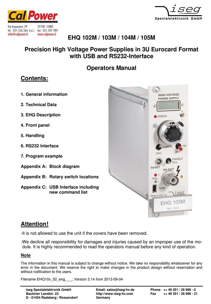
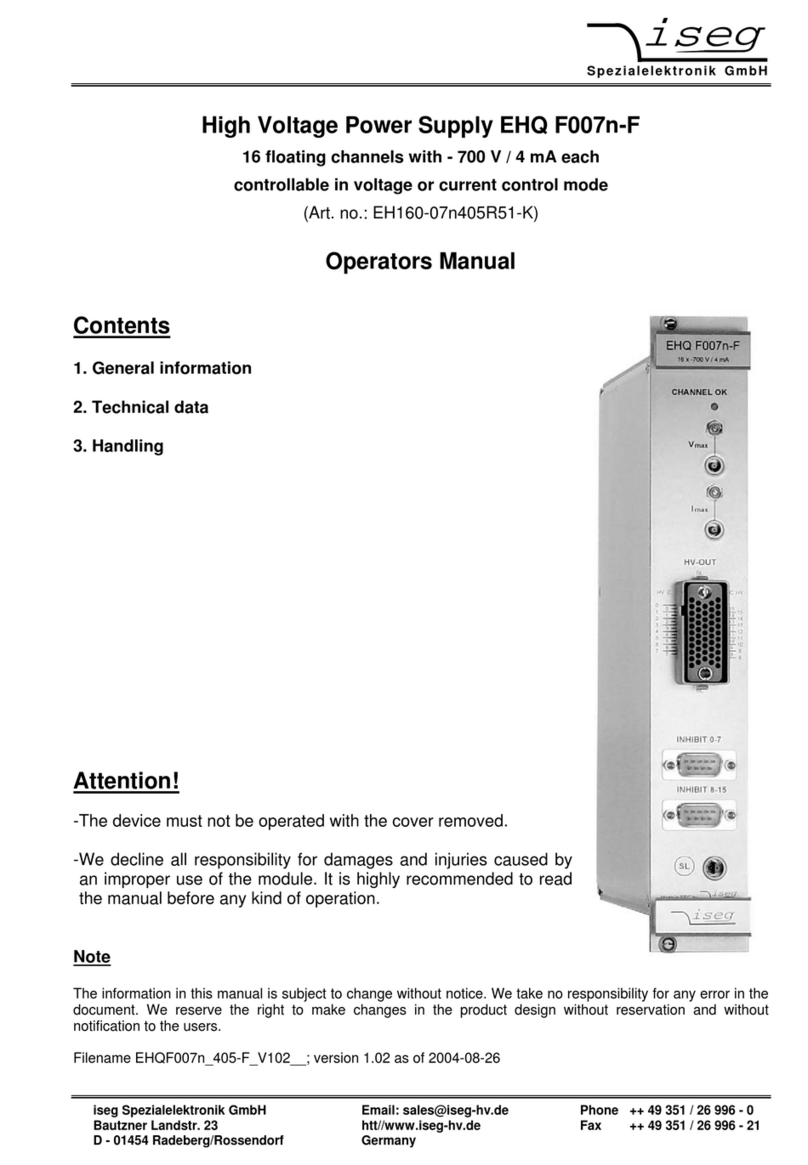
High Voltage Power Supply EHQ 8007n-F
8 floating channels with - 700 V / 4 mA each
(Art. no.: EH080-07n405R51-K)
Operators Manual
Contents
1. General information
2. Technical data
3. Handling
Attention!
-The device must not be operated with the cover removed.
-We decline all responsibility for damages and injuries caused by an improper use of the
module. It is highly recommended to read the manual before any kind of operation.
Note
The information in this manual is subject to change without notice. We take no responsibility for any error in the
document. We reserve the right to make changes in the product design without reservation and without
notification to the users.
Filename EHQ8007n_405-F_V1.00__; version 1.00 as of 2004-06-04
Spezialelektronik GmbH
iseg Spezialelektronik GmbH Email: [email protected] Phone ++ 49 351 / 26 996 - 0
Bautzner Landstr. 23 http://www.iseg-hv.com Fax ++ 49 351 / 26 996 - 21
D - 01454 Radeberg/Rossendorf Germany 2
1. General information
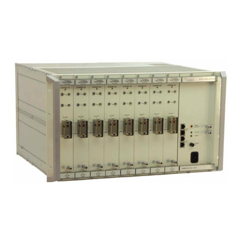
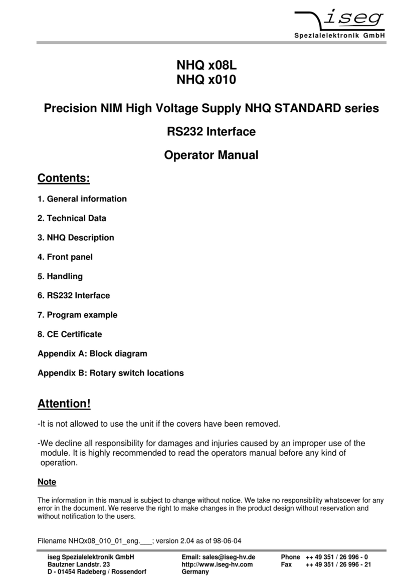
The EHQ 8007n_405-F is a 8-channel high voltage power supply in 6U Eurocard format. Each single
channel is independently controllable in voltage or current control mode. The outputs HV-out positive
- floating HV-GND - and HV-out negative of each channel are both floating against each other and
against ground.
The EHQ 8007n_405-F is made ready for mounting into a crate. It is also possible to supply the
modules separately with the necessary power. The unit is software controlled via CAN Interface
directly through a PC or similar controller. The HV output at the EHQ 8007n_405-F is equipped with a
REDEL connector.
2. Technical data
CHANNEL OK
SL
HV-OUT
HV C
SL
SL
0 0
1
2
3
4
5
6
7
1
2
3
4
5
6
7 8 9
9
10
11
12
13
14
15
8
10
11
12
13
14
15
C HV
I V
max max
INHIBIT 0-7
8 x -700V / 12 mA
EHQ 8007n-F
EHQ 8007n_405 - F
Output current IOmax. 4 mA
Output voltage VO0 to 700 V
Floating Connector “C” (+) to GND: ≤⏐20 V⏐
Connector “HV” (-) to GND: ≤⏐20 V⏐- VO
Ripple and noise < 20 mV (at max. load and VO> 50 V)
Interface CAN-Interface
Voltage setting Via software, resolution 14 mV
Current setting Via software, resolution 80 nA
Voltage measurement Via software, resolution 14 mV
Current measurement Via software, resolution 80 nA
Accuracy of measurement Voltage: ±(0,01% ∗VO+ 0,02% ∗VO max)
(for one year) Current: ±(0,01% ∗IO+ 0,01% ∗IO max)
Temperature coefficient < 5 ∗10-5/K
Stability < 5 ∗10-5 (no load/load and ∆VIN)
Rate of change of
output voltage Via software:
0,28 V/s to 70 V/s resolution 0,5 V
Channel control
via software Status 8 bit: channel error, KILL- enable, channel
emergency cut-off, ramp, channel on/off, input error,
current trip
8 channels error control via
hardware limit Current limit
Voltage limit (″Channels 0-7 OK″is signalled if
these limits do not exceed on each.)
Error signal Green LED at ″Channels 0-7 OK″
Protection loop (SL),
2 pin Lemo-socket 5 mA < Is < 20 mA ⇒module on
I
s < 0,5 mA ⇒module off
Protection loop per channel, Ch0 Ch1 Ch2 Ch3 Ch4 Ch5 Ch6 Ch7 GND
Sub-D-9 connector; PIN 1 2 3 4 5 6 7 8 9
Power requirements VIN + 24 V (< 1,5 A) and + 5 V (< 0,5 A)
Packing 8-channels in 6U Euro cassette
(40,64 mm wide and 220 mm deep)
Connector 96-pin connector according to DIN 41612
HV connector REDEL connector equipped with 16 pins
Spezialelektronik GmbH
iseg Spezialelektronik GmbH Email: [email protected] Phone ++ 49 351 / 26 996 - 0
Bautzner Landstr. 23 http://www.iseg-hv.com Fax ++ 49 351 / 26 996 - 21
D - 01454 Radeberg/Rossendorf Germany 3
3. Handling
The supply voltages and the CAN interface is connected to the module via a 96-pin connector on the
rear side of the module.
The maximum output current and voltage for all channels is defined through the position of the
corresponding potentiometer Imax or Vmax at the front panel.
The output current and voltage will be limited to the setting value after it exceeds the threshold and
the green LED on the front panel is ‘OFF‘.
If the HV channel should work in the current control mode (IOaccording ISET via software), the KILL
function must be disable for this channel.
At the bottom on the right upper side of the front panel is the socket for the safety loop. If the safety
loop is active then output voltage on all channels is only present if a current is flowing in a range of 5
to 20 mA of any polarity ( i.e. safety loop closed). If the safety loop is opened during operation then
the output voltages are shut off without ramp and the corresponding bit in the ‘Status module’ will be
cancelled. After the loop will be closed again the channels must be switched ‘ON’ and a new set
voltage must be given before it is able to offer an output voltage. The pins of the loop are potential
free, the internal voltage drop is ca. 3 V. Coming from the factory the safety loop is not active (the
corresponding bit is always set). Removing of an internal jumper makes the loop active (s. App. A).
Additionally it is possible to install a safety loop for each channel (n= 0 to 7) via the Sub-D-9
connector. If the INHIBIT contact pin (n) will be connected to the GND pin then the HV-PS on this
channel will be switched off without ramp. The GND pins are internally connected to the module GND.
Attention: If this will be disconnected again, then the HV will be set -according to the present VSET -
to VOUT without ramp! Please shut the channel “OFF” or write VSET= 0 before!
The connector HV-out positive - floating HV-GND - of each channel should be connected to ground at
a certain chosen point. Otherwise it must be sure, that the potential between HV-out positive and
GND should not exceed the amount of ⎪20 V⎪.
Pin assignment 96-pin connector according to DIN 41612:
PIN PIN PIN Data
a1 b1 c1 +5V
a3 b3 c3 +24V
a5 b5 c5 GND
a11 @CAN_GND ⎫
b11 @CANL ⎬potential free
c11 @CANH ⎭
a13 RESET
b13 OFF with ramp (e.g. 10s after power fail)
a30 A4 b30 A5 c30 GND ⎫
a31 A2 b31 A3 c31 GND ⎬Address field
a32 A0 b32 A1 c32 GND ⎭module address ( A0 ... A5)
The hardware signal “OFF with ramp” (Pulse High-Low-High, pulse width ≤100 µs) on pin b13 will be
shut off the output voltage for all channels with a ramp analogue to the Group access “Channel
ON/OFF”. The ramp speed is defined to VOUTmax / 50 s. This is the actually module ramp speed after
“OFF with ramp”.
With help of the Group access “Channel ON/OFF”all channels are switched “ON” again.
With the address field a30/b30 ..... a32/b32 the module address will be coded.
Connected to GND ⇒A(n) = 0 ; contact open ⇒A(n) = 1

This manual suits for next models

1

Other iseg Power Supply manuals

iseg CalPower EHQ 102M User manual

iseg

iseg CalPower EHQ 102M User manual

iseg HPS 300 W User manual

iseg

iseg HPS 300 W User manual

iseg GPS Series Guide

iseg

iseg GPS Series Guide

iseg NHS Series Manual

iseg

iseg NHS Series Manual

iseg SHQ 122 User manual

iseg

iseg SHQ 122 User manual

iseg NHS Series Manual

iseg

iseg NHS Series Manual

iseg ECH 128 User manual

iseg

iseg ECH 128 User manual

iseg HPS Series User manual

iseg

iseg HPS Series User manual

iseg EHQ F007n-F User manual

iseg

iseg EHQ F007n-F User manual

iseg ECH 238 User manual

iseg

iseg ECH 238 User manual

iseg ECH 238 1200W User manual

iseg

iseg ECH 238 1200W User manual

iseg NHQ STANDARD Series User manual

iseg

iseg NHQ STANDARD Series User manual

iseg HPS 300 W series User manual

iseg

iseg HPS 300 W series User manual

iseg NHR Series Guide

iseg

iseg NHR Series Guide

iseg THQ Series Guide

iseg

iseg THQ Series Guide

iseg VHQ 202M User manual

iseg

iseg VHQ 202M User manual

iseg EPS Series User manual

iseg

iseg EPS Series User manual

iseg EHQ 9005-F User manual

iseg

iseg EHQ 9005-F User manual

iseg EBS F 030 User manual

iseg

iseg EBS F 030 User manual

iseg SHR Standard User manual

iseg

iseg SHR Standard User manual

iseg SHQ Series User manual

iseg

iseg SHQ Series User manual

Popular Power Supply manuals by other brands

Lucent Technologies CIB 2866 manual

Lucent Technologies

Lucent Technologies CIB 2866 manual

Abysm Gaming MORPHEO ATX 1000W PLUS PLATINUM user manual

Abysm Gaming

Abysm Gaming MORPHEO ATX 1000W PLUS PLATINUM user manual

Thermaltake W0156 Specifications

Thermaltake

Thermaltake W0156 Specifications
NURZVIY DISCOVER 100 user manual

NURZVIY

NURZVIY DISCOVER 100 user manual

Beckhoff PS3031-2440-0000 Documentation

Beckhoff

Beckhoff PS3031-2440-0000 Documentation

GV D1010S-046 instruction manual

GV

GV D1010S-046 instruction manual

Larson Electronics S-23-13.8V manual

Larson Electronics

Larson Electronics S-23-13.8V manual

Cooler Master RS-700-AFBA-G1 user manual

Cooler Master

Cooler Master RS-700-AFBA-G1 user manual

BougeRV 1100WH user manual

BougeRV

BougeRV 1100WH user manual

EVGA 80 PLUS BRONZE 500 BQ user manual

EVGA

EVGA 80 PLUS BRONZE 500 BQ user manual

Bogen SPS2454 Installation

Bogen

Bogen SPS2454 Installation

Keithley 2606B System SourceMeter Reference manual

Keithley

Keithley 2606B System SourceMeter Reference manual

StarTech.com ATXPOW330HS instruction manual

StarTech.com

StarTech.com ATXPOW330HS instruction manual

Signal Recovery PS0055 operating instructions

Signal Recovery

Signal Recovery PS0055 operating instructions

Avid Technology VENUE E6L manual

Avid Technology

Avid Technology VENUE E6L manual

Baintech PowerTop user guide

Baintech

Baintech PowerTop user guide

Pulsar PSCV3512 quick start guide

Pulsar

Pulsar PSCV3512 quick start guide

Antec TruePower Gold TP-550G user manual

Antec

Antec TruePower Gold TP-550G user manual

manuals.online logo
manuals.online logoBrands
  • About & Mission
  • Contact us
  • Privacy Policy
  • Terms and Conditions

Copyright 2025 Manuals.Online. All Rights Reserved.