iseg CalPower EHQ 102M User manual

Spezialelektronik GmbH
Bautzner Landstr. 23 http://www.iseg-hv.com Fax ++ 49 351 / 26 996 - 21
D - 01454 Radeberg / Rossendorf Germany
EHQ 102M / 103M / 104M / 105M
Precision High Voltage Power Supplies in 3U Eurocard Format
with USB and RS232-Interface
Operators Manual
Contents:
1. General information
2. Technical Data
3. EHQ Description
4. Front panel
5. Handling
6. RS232 Interface
7. Program example
Appendix A: Block diagram
Appendix B: Rotary switch locations
Appendix C: USB Interface including
new command list
Attention!
-It is not allowed to use the unit if the covers have been removed.
-We decline all responsibility for damages and injuries caused by an improper use of the mo-
dule. It is highly recommended to read the operators manual before any kind of operation.
Note
The information in this manual is subject to change without notice. We take no responsibility whatsoever for any
error in the document. We reserve the right to make changes in the product design without reservation and
without notification to the users.
Filename EHQ10x_02_eng.___; Version 3.14 from 2013-09-04
Via Acquanera, 29 22100 Como
tel. 031.526.566 (r.a.) fax 031.507.984
info@calpower.it www.calpower.it

Spezialelektronik GmbH
Bautzner Landstr. 23 http://www.iseg-hv.com Fax ++ 49 351 / 26 996 - 21
2 D - 01454 Radeberg / Rossendorf Germany

Spezialelektronik GmbH
Bautzner Landstr. 23 http://www.iseg-hv.com Fax ++ 49 351 / 26 996 - 21
D - 01454 Radeberg / Rossendorf Germany 3
1. General information
The EHQ´s are one channel high voltage supplies in a 3U Eurocard Chassis, 8TE wide. The units offers manual
control via the front panel and operation via USB and RS232 interface (optional: CAN Bus interface). The
interface control supports more functionality then the manual control.
The high voltage supplies features high precision output voltage and very low ripple, even under full load.
Separate hardware switches allow to put voltage and current limits in 10%-steps. The INHIBIT input protects
sensitive devices. Additionally, a maximum output current can be specified via the interface. The high voltage
source is protected against overload and short circuit. The output polarity can be switched over. The HV-GND is
connected to the chassis and the powering GND.
2. Technical data
Type (with USB and RS 232) EHQ 102M EHQ 103M EHQ 104M EHQ 105M
Output voltage VO nom 0 ... 2 kV 0 ... 3 kV 0 ... 4 kV 0 ... 5 kV
Output current IO nom 6 mA 4 mA 3 mA 2 mA
Option N12 3 mA 2 mA 1 mA 1 mA
Option 104 100 µA 100 µA 100 µA 100 µA
Ripple and noise < 2 mVP-P < 5 mVP-P
Resolution of current measurement 1 µA; option 104: IO nom = 100 µA ⇒100 nA
Resolution of voltage measurement 1 V
Accuracy current measurement ± (0,05% IO+ 0,02% IO nom + 1 digit) for one year
voltage measurement ± (0,05% VO+ 0,02% VO nom + 1 digit) for one year
The measurement accuracy is guaranteed only in the range 1% ∗VO nom < VO≤VO nom !
LCD display 4 digits with sign, switch controlled
voltage display in [V]
current display in [A], with option 104 in [mA]
Stability ∆VO(no load / load) < 5 ∗10-5
∆VO/VINPUT < 5 ∗10-5
Temperature coefficient < 5 ∗10-5/K
Voltage control CONTROL switch in position
-manual: 10-turn potentiometer,
-DAC: control via serial interface
Rate of change of HV -ON/OFF 500 V/s (hardware ramp)
output voltage remote control 2 ... 255 V/s (software ramp)
Protection -separate current and voltage limit
(hardware, rotary switch in10%-steps)
-INHIBIT (external signal, TTL level, Low=active)
-programmable current limit (software)
Power requirement VIN ±24 V (< 500 mA), option: ±12 V (< 500 mA)
Temperature ranges operating: 0 . . . 50 °C storage: -20 . . . +60 °C
Packing 3U Euro cassette / 160 mm depth / 40,8 mm wide
Connectors 96-pin connector according to DIN 41612 on the rear,
USB mini B on the front panel
HV connector SHV-Connector at the front panel
Inhibit connector 1-pin Lemo-hub

Spezialelektronik GmbH
Bautzner Landstr. 23 http://www.iseg-hv.com Fax ++ 49 351 / 26 996 - 21
4 D - 01454 Radeberg / Rossendorf Germany
3. EHQ Description
The functional principle is described in the block diagram, Appendix A.
High voltage supply
For the high voltage generation a patented highly efficient resonance converter circuit is used, which provides a
sinusoidal voltage with low harmonics for the HV-transformer. For the high voltage rectification high speed HV-
diodes are used. A high-voltage switch, connected to the rectifier allows the selection of the polarity. The
consecutive active HV-filter damps the residual ripple and ensures low ripple and noise values as well as the
stability of the output voltage. A precision voltage divider is integrated in the HV-filter to provide a feedback
voltage for the output voltage control, an additional voltage divider supplies the signal for the maximum voltage
monitoring. A precision control amplifier compares the feedback voltage with the set value given by the DAC
(remote control) or the potentiometer (manual control). Signals for the control of the resonance converter and
the stabilizer circuit are derived from the result of the comparison. The two-stage layout of the control circuit
results in an output voltage, stabilized with very high precision to the set point.
Separate security circuits prevent exceeding the front-panel switch settings for the current Imax and voltage Vmax
limits. A monitoring circuit prevents malfunction caused by low supply voltage.
The internal error detection logic evaluates the corresponding error signals and the external INHIBIT signal and
impacts the output voltage according to the setup. In addition this allows the detection of short over currents
due to single flashovers.
Digital control unit
A micro controller handles all internal control, evaluation and calibration functions. The actual voltages and
currents are read cyclically by an ADC with a connected multiplexer. The readings are processed and displayed
on the 4 digit LCD. The current and voltage hardware limits are retrieved cyclically several times per second. A
reference voltage source provides a precise voltage reference for the ADC and the control voltage for the
manual operation mode of the unit.
In the computer controlled mode the set values for the corresponding channels are generated by a 16-Bit DAC.
Filter
A special feature of the unit is a tuned filtering concept, which prevents perturbation of the unit by external
electromagnetic radiation, as well as the emittance of interferences by the module. A filtering network for the
supply voltages is located next to their connectors, the converter circuits of the individual channels are
protected by additional filters. The high-voltage filters are housed in individual metal enclosures to shield even
minimal interference radiation.

Spezialelektronik GmbH
Bautzner Landstr. 23 http://www.iseg-hv.com Fax ++ 49 351 / 26 996 - 21
D - 01454 Radeberg / Rossendorf Germany 5
4. Front panel
[1] 4 digit LCD display
[2] Error indicator
[3] Measuring switch
[4] 10-turn potentiometer
[5] HV-ON switch
[6] CONTROL switch
[7] KILL switch
[8] INHIBIT input
[9] HV-ON indicator
[10] HV output
[11] Polarity indicator
5. Handling
The unit is set into operating state by connecting at the 96-pin connector according to DIN 41612 on the
backside. This also attaches the RS232 interface. The USB interface is connected via the
USB mini B connector on the frontpanel (below the polarity indicator).
Before the unit is powered the desired output polarity must be selected by the rotary switch on the cover side
(see appendix B). The chosen polarity is displayed by a LED on the front panel [11] and a sign on the LCD [1].
Attention! It is not allowed to change the polarity under power!
An undefined switch setting (not at one of the end positions) will cause no output voltage.
High voltage output is switched on with HV-ON switch [5] at the front panel. The viability is signalled by the
yellow LED [9].
Attention!
If the CONTROL switch [6] is in upper position (manual control), high voltage is generated
at the HV-output [10], started with a ramp speed from 500 V/s (hardware ramp) to the set
voltage given by the 10-turn potentiometer [4].
This is also the case, if DAC control is switched over to manual control while operating.
If the CONTROL switch [6] is in lower position (DAC), high voltage will be activated only after receiving
corresponding serial interface (DAC) commands.
Attention! If the function ″Autostart″has been activated in the previous operating session, the high
voltage generation starts immediately with the saved parameters!

Spezialelektronik GmbH
Bautzner Landstr. 23 http://www.iseg-hv.com Fax ++ 49 351 / 26 996 - 21
6 D - 01454 Radeberg / Rossendorf Germany
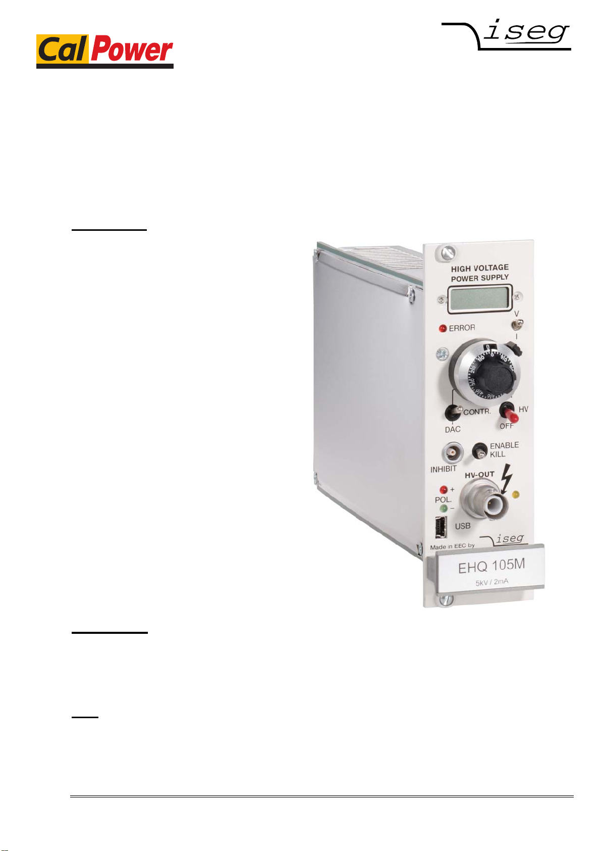
The LCD [1] displays the output voltage in [V] or the output current in [µA], depending on the position of the
Measuring switch [3].
In the manual control mode the output voltage can be set via 10-turn potentiometer [4] in a range from 0 to the
maximum voltage.
If the CONTROL switch [6] is switched over to serial interface control (DAC), the DAC takes over the last set
output voltage of the manual control. The output voltage can be changed remotely with a programmable ramp
speed (software ramp) from 2 to 255 V/s in a range from 0 to the maximum voltage.
The maximum output current for each channel (current trip) can be set via the remote interface in units of the
resolution of the upper measurement range. If the output current exceeds the programmable limit, the output
voltage will be shut off permanently by the software. A recovery of the voltage is possible after ”Read status
word”and then ”Start voltage change”via serial interface. If ”Auto start”is active, ”Start voltage change”is
not necessary.
The maximum output voltage and current can be selected in 10%-steps with the rotary switches Vmax and Imax
(switch dialled to 10 corresponds to 100%) on the cover side (see appendix B) independently of programmable
current trip. The red error LED on the front panel [2] signals if the output voltage or current approaches the
limits.
The KILL switch [7] specifies the response on exceeding limits or on the external protection signal at the
INHIBIT input [8] as follows:
Switch to the right position:
(ENABLE KILL) When exceeding Vmax, Imax or in the presence of an INHIBIT signal (Low=active)
the output voltage will be shut off permanently without ramp. The output voltage
is only restored after switching HV-ON [5] or KILL [7] or ”Read status word”
and then ”Start voltage change”by DAC control. If ”Auto start”is active,
”Start voltage change”is not necessary.
Note: If a capacitance is effective at the HV-output or when using a high voltage ramp
speed (hardware ramp) under high loads, then the KILL function may be
triggered by the capacitor charging currents. In this case smaller output voltage
change rates (software ramp) should be used or ENABLE KILL should only be
selected once the set voltage is reached at the output.
Switch to the left position:
(DISABLE KILL) The output voltage is limited to Vmax, the output current to Imax respectively;
INHIBIT shuts the output voltage off without ramp, the previous voltage setting
will be restored with hard- or software ramp once INHIBIT no longer being
present.
6. RS232 interface resp. USB interface
The following functionality is provided for the operation of the high voltage units via the serial interface.
Serial interface control mode
- Write function: set voltage; ramp speed; maximal output current (current trip); auto start
- Switch function: output voltage = set voltage, output voltage = 0
- Read function: set voltage; actual output voltage; ramp speed; actual output current;
current trip; auto start ; hardware limits current and voltage; status
Front panel switches have priority over software control.
Manual control mode
While the unit is operated in manual control mode, RS232 read cycles are interpreted only. Commands are
accepted, but do not result in a change of the output voltage.

Spezialelektronik GmbH
Bautzner Landstr. 23 http://www.iseg-hv.com Fax ++ 49 351 / 26 996 - 21
D - 01454 Radeberg / Rossendorf Germany 7
Pin assignment 96-pin connector on the flip side
A3 B3 C3 +24V
A5 B5 C5 GND, connected to chassis and HV-GND
A7 B7 C7 -24V
A9 @GND ⎫
B9 @RXD ⎬potential free
C9 @TXD ⎭
Specification of the RS232 interface
The data exchange is character based, the synchronisation for the transfer direction PC to HV-source (input) is
performed using an echo. The data transfer to the PC (output) is asynchronous. Between two characters a
programmable delay time is included to allow the computer to receive and evaluate the incoming data. The
default delay time setting is 3 ms.
The hardware setting of the RS232 interface is 9600 bit/s, 8 bit/character, no parity, 1 stop bit.
Signal transmission is performed potential free via the @RxD and @TxD, relative to @GND. The pin
assignment at the PC side is given in table 1. The bridging on the PC side if a three-lead cable is used, is also
given in table 1.
Syntax
The commands are transmitted in ASCII. All commands are terminated by the sequence
<CR> <LF> ( 0x0D 0x0A , 13 10 respectively). Leading zeroes can be omitted on input, output is in fixed
format.
Table 1: Signal PC PC Connection
RS 232 DSUB9 DSUB25 3-lead cable
Signal pin assignment RxD 2 3
TxD 3 2
GND 5 7
4 20
─┐
6 6
─┤
8 5
─┘

Spezialelektronik GmbH
Bautzner Landstr. 23 http://www.iseg-hv.com Fax ++ 49 351 / 26 996 - 21
8 D - 01454 Radeberg / Rossendorf Germany
Command set
Command Computer HV-supply
Read module identifier # * # * nnnnnn ; n.nn ; U ; I *
(unit number; softwarerel. ; Vout [V] ; Iout [µA])
Read break time W * W * nnn * (break time 2 ... 255 ms)
Write break time W=nnn * W=nnn * * (break time = 2 - 255 ms)
Read actual voltage channel 1 U1 * U1 * {polarity / voltage} * (in V)
Read actual current channel 1 I1 * I1 * {mantisse / exp. with sign} * (in A)
Read voltage limit channel 1 M1 * M1 * nnn * (in % of Vout max)
Read current limit channel 1 N1 * N1 * nnn * (in % of Iout max)
Read set voltage channel 1 D1 * D1 * {voltage} * (in V)
Write set voltage channel 1 D1=nnnn * D1=nnnn * * (voltage in V; <M1)
Read ramp speed channel 1 V1 * V1 * nnn * (2 ... 255 V/s)
Write ramp speed channel 1 V1=nnn * V1=nnn * * (ramp speed = 2 - 255 V/s)
Start voltage change channel 1 G1 * G1 * S1=xxx * (S1 , ⇒Status information)
Write current trip cannel 1 L1=nnnn * L1=nnnn * * (corresponding resolution current > 0)
Read current trip channel 1 L1 * L1 * nnnn * (s.a., for nnnn=0 ⇒no current trip)
Read status word channel 1 S1 * S1 * xxx * (S1 , ⇒Status information)
Read module status channel 1 T1 * T1 * nnn * (code 0...255, ⇒Module status)
Write auto start channel 1 A1=nn * A1=nn * * (conditions ⇒Auto start)
Read auto start channel 1 A1 * A1 * n * (8 ⇒auto start is active; 0 ⇒inactive)
* = <CR><LF>
Status information:
xxx: ON<SP> Output voltage according to set voltage
OFF Channel is switched off via the front panel switch
MAN Channel is on, set to manual mode
ERR Vmax or Imax is / was exceeded
INH Inhibit signal was / is active
QUA Quality of output voltage not given at present
L2H Output voltage increasing
H2L Output voltage falling
LAS Look at Status (only after G-command)
TRP Current trip was active
If output voltage has been shut off permanently (by ERR or INH at ENABLE KILL or TRP) the command ”Read
status word”must be executed before the output voltage can be restored.

Spezialelektronik GmbH
Bautzner Landstr. 23 http://www.iseg-hv.com Fax ++ 49 351 / 26 996 - 21
D - 01454 Radeberg / Rossendorf Germany 9
Error codes:
???? Syntax error
?WCN Wrong channel number
?TOT Timeout error (with following reinitialization)
?<SP>UMAX=nnnn Set voltage exceeds voltage limit
Module status:
Status Description Bit Valency
QUA Quality of output voltage not given at present 7=1 128
ERR Vmax or Imax is / was exceeded 6=1 64
INH INHIBIT signal was / is active 5=1 32
inactive 0
KILL_ENA KILL-ENABLE is on 4=1 16
off 0
OFF Front panel HV-ON switch in OFF position 3=1 8
ON position 0
POL Polarity set to positive 2=1 4
negative 0
MAN Control manual 1=1 2
via RS 232 interface 0
T1: U/I Display dialled to voltage measurement 0=1 1
current measurement 0
Auto start:
Description Bit Valency
If the precondition for Auto start (module status: OFF + ERR + INH + MAN = 0) is
satisfied, the output voltage is automatically ramped to the set voltage. Thus the G-
command or POWER-ON and OFF ⇒ON are not required.
If output voltage has been shut off permanently (by ERR or INH at ENABLE KILL or
TRP), the previous voltage setting will be restored with software ramp after ”Read
status word”.
3=1 8
Values are written to the registers only Save Current trip to EEPROM 2=1 4
at POWER-ON! Save Set voltage to EEPROM 1=1 2
Save Ramp speed to EEPROM 0=1 1
(EEPROM guarantees a minimum of 1 million
saving cycles)
Software
Contact us for an overview on our user friendly control and data acquisition software!

Spezialelektronik GmbH
Bautzner Landstr. 23 http://www.iseg-hv.com Fax ++ 49 351 / 26 996 - 21
10 D - 01454 Radeberg / Rossendorf Germany
7. Program example
/***************************************************************************************************/
/* */
/* ehq.cpp */
/* */
/* example program for iseg ehq hv boards, written by Jens Römer, 27.2.97 */
/* */
/* this code was compiled under BC, please contact iseg for the source file */
/* */
/***************************************************************************************************/
#include <dos.h>
#include <stdio.h>
#include <conio.h>
#include <stdlib.h>
#include "int14.h" // COM2 handling
const etx= 0x03;
const f = 0x0a;
const cr = 0x0d;
unsigned char readU[]={'U','1',cr,lf,etx}; //read voltage
unsigned char sendU[]={'D','1','=','1','0',cr,lf,etx}; //set voltage to 10V
unsigned char *ptr;
unsigned char rby;
int i, cnt;
boolean ok;
void main(void)
{
clrscr();
COM2_init();
COM2_set(9600); // COM2: 9600 baud, 8 databits, no parity, 1 stopbit
ok=True_;
ptr=readU;
for (;;)
{
if (*ptr==etx) break;
COM2_send(*ptr); //send one byte
rby=COM2_read(); //read one byte
if (rby!=*(ptr++)) ok=False_; //compare sent with read data
else switch (rby)
{
case lf : printf("%c",lf); break;
case cr : printf("%c",cr); break;
default : printf("%c",rby); break;
}
if (ok==False_)
{
printf("No coincident read data found!");
exit(1);
}
}
cnt=8;
do
{
rby=COM2_read(); //read voltage data
switch (rby)
{
case lf : printf("%c",lf); break;
case cr : printf("%c",cr); break;
default : printf("%c",rby); break;
}
cnt--;
} while (cnt>=1);
}

Spezialelektronik GmbH
Bautzner Landstr. 23 http://www.iseg-hv.com Fax ++ 49 351 / 26 996 - 21
D - 01454 Radeberg / Rossendorf Germany 11
LCD display / driver
Microcontroller
Reference
voltage
ADC
MUX
DAC 1
DAC 2
Front panel
Operating elements
Resonance Converter
HV-Transformer
Rectifier
Polarity
switch HV-Filter HV-
OUTPUT
Channel A
rectifier
AGC amplifier
Precision-
V monitoring
max
I monitoring
max
Error logic
Inhibit
Supply voltage
monitoring
Hardware
voltage ramp
Filter
+/-24V
96-pin connector according to DIN 41612
Filter
Appendix A: Block diagram EHQ

Spezialelektronik GmbH
Bautzner Landstr. 23 http://www.iseg-hv.com Fax ++ 49 351 / 26 996 - 21
12 D - 01454 Radeberg / Rossendorf Germany
Imax
Vmax
10 2
46
810 2
46
8
POLARITY
NEG
POS
Appendix B: EHQ side cover
Polarity rotary switch (e.g.: polarity negative)
RotaryswitchesforV
max and Imax

Spezialelektronik GmbH
Appendix C: Users Manual attachment
Hints for the use of EHQ 1 channel with new command list
The remote control of the unit can either be done with the new SCPI command list described in the
following or with the old DCP command list described in the operators manual
“EHQ 102M / 103M / 104M / 105M” see page 6 to 10
Switching between the different command sets can be done with the following commands:
*INSTR? query the selected instruction set
reply EDCP or DCP
*INSTR,SCPI
or
*INSTR,EDCP select SCPI instruction set
*INSTR,iseg
or
*INSTR,DCP select old iseg instruction set
iseg Spezialelektronik GmbH Email: sales@iseg-hv.de Phone ++ 49 351 / 26 996 - 0
Bautzner Landstr. 23 http://www.iseg-hv.com Fax ++ 49 351 / 26 996 - 21
D - 01454 Radeberg / Rossendorf Germany

Spezialelektronik GmbH
iseg SCPI command set
Command Description
:VOLTage
<Voltage>[V]
<EMCY OFF>
<EMCY CLR>
:BOUnds <voltage>[V]
set channel voltage
shut channel emergency off
clear shut channel emergency off
set channel voltage bounds
:CURRent
<Current>[A]
:BOUnds <current>[A] set channel current
set channel current bounds
:Event
<CLEAR>
:MASK <word> clear channel events
set channel event mask
:TRIP
:TIME <time>[ms]
:ACTivity <action> defines a span between 8 and 4000 ms for the
delayed trip
action:
0 ignore the failure
1 switch off this channel by ramp down the voltage
2 switch off this channel by an internal EmergencyOff
3 switch off the whole HV board by set EmergencyOff.
:CONFigure
:RAMP
:VOLTage<RampSpeed>[V/s]
:CURRent<RampSpeed>[A/s]
:EVent
:MASK
:CHANMASK
:ECHO?
ON
OFF
set/get module configuration
set module voltage ramp speed
set module current ramp speed
clear channel events
set channel event mask
receive characters with an echo
receive characters without echo
:MEASure
:VOLTage?
:CURRent? query measured channel voltage
query measured channel current
iseg Spezialelektronik GmbH Email: sales@iseg-hv.de Phone ++ 49 351 / 26 996 - 0
Bautzner Landstr. 23 http://www.iseg-hv.com Fax ++ 49 351 / 26 996 - 21
2 D - 01454 Radeberg / Rossendorf Germany

Spezialelektronik GmbH
Command Description
:READ
:VOLTage?
:LIMit?
:NOMinal?
:BOUnds?
:CURRent?
:LIMit?
:NOMinal?
:BOUnds?
:RAMP
:VOLTage?
:CURRent?
:MODule
:CONTrol?
:STATus?
:EVent
:STATus?
:MASK?
:CHANSTATus?
:CHANMASK?
:SUPply
:P24V?
:N24V?
:P12V?
:N12V?
:TEMPerature?
:CHANel
:CONTrol?
:STATus?
:EVent
:STATus?
:MASK?
:TRIP
:TIME?
:ACTivity?
:IDNT?
query voltage limit
query channel voltage nominal
query channel current bounds
query current limit
query channel current nominal
query channel current bounds
query voltage ramp speed
query current ramp speed
query module control word
query module status word
query module event status word
query module event mask word
query module channel event status
query module channel event mask
query module supply +24V
query module supply -24V
query module supply +12V
query module supply -12V
query measured temperature
query channel control word
query channel status word
query channel event status word
query channel event mask word
query the time span of the time out function for the delayed
trip in ms
query the action of the delayed trip function when the time
has been exceeded (see :TRIP:ACT)
query module identification
Examples:
Set Voltage to 1000.501V :VOLT1000.501
Set Current to 1.58mA :CURR0.00158
Set Voltage Ramp speed to 30 Volt per second :CONF:RAMP:VOLT30
Query serial Echo status CONF:ECHO?
Enable serial Echo CONF:ECHOON
Advanced Examples:
:VOLT 2000.5; :READ:VOLT?; :CURR 0.002; :READ:CURR?
:MEAS:VOLT?;CURR?
20000.284V; 1999.731E-6A
Bautzner Landstr. 23 http://www.iseg-hv.com Fax ++ 49 351 / 26 996 - 21
D - 01454 Radeberg / Rossendorf Germany 3

Spezialelektronik GmbH
Channel status (read access)
:READ:CHANnel:STATus? UI2
Bit15 Bit14 Bit13 Bit12 Bit11 Bit10 Bit9 Bit8 Bit7 Bit6 Bit5 Bit4 Bit3 Bit2 Bit1 Bit0
isVLIM isCLIM isTRP isEINH isVBND isCBND res res isCV isCC isEMCY isRAMP isON IERR isREG res
The ChannelStatus register describes the actual status. Depending on the status of the module the
bits will be set or reset.
The bit InputError will be set if the given parameter is not plausible or it exceeds the module
parameters (e.g. if the command Vset=4000V is given to a module with NominalVoltage=3000V). The
bit InputError is not set if the given values are temporarily not possible (e.g. Vset=2800 at a module
with NominalVoltage=3000V, but HardwareLimitVoltage=2500V). A certain signature which kind of
input error it is does not exist.
isVLIM IsVoltageLimitExceeded voltage limit set by Vmax is exceeded
IsCLIM IsCurrentLimitExceeded current limit set by Imax is exceeded
isTRP IsTripExceeded Trip is set when Voltage or Current limit or Iset has been exceeded (when KillEnable=1 )
isEINH IsExtInhibit External Inhibit
isVBND IsVoltageBoundsExceeded Voltage out of bounds
isCBND IsCurrentBoundsExceeded Current out of bounds
isCV IsControlledVoltage Voltage control active (evaluation is guaranteed when no ramp is running)
isCC IsControlledCurrent Current control active (evaluation is guaranteed when no ramp is running)
isEMCY IsEmergencyOff Emergency off without ramp
isON IsOn On
isRAMP IsRamping Ramp is running
IERR InputError Input error
isREG IsRegulationError faster error detection of the channel hardware is not in regulation (check it every 5ms)
res Reserved
isVLIM=0 channel is ok
isVLIM=1 the hardware voltage limit is exceeded
isCLIM=0 channel is ok
isCLIM=1 the hardware current limit is exceeded
isTRP=0 channel is ok
isTRP=1 VOis shut off to 0V without ramp because the channel has tripped.
isEINH=0 channel is ok
isEINH=1 External Inhibit was scanned
isVBND=0 channel is ok
isVBND=1 |Vmeas - Vset| > Vbounds
isCBND=0 channel is ok
isCBND=1 |Imeas - Iset| > Ibounds
isCV=1 channel is in state of voltage control
isCC=1 channel is in state of current control
isEMCY=1 channel is in state of emergency off,
VO has been shut off to 0V without ramp
isON=0 channel is off
isON=1 channel voltage follows the Vset value
isRAMP=0 no voltage is in change
isRAMP=1 voltage is in change with the stored ramp speed value
IERR=0 no input-error
IERR=1 incorrect message to control the module
isREG=0 normal error evaluation
isREG=0 fast detection of a regulation error (OPTION)
iseg Spezialelektronik GmbH Email: sales@iseg-hv.de Phone ++ 49 351 / 26 996 - 0
Bautzner Landstr. 23 http://www.iseg-hv.com Fax ++ 49 351 / 26 996 - 21
4 D - 01454 Radeberg / Rossendorf Germany

Spezialelektronik GmbH
Channel event status (read access)
:READ:CHANnel:EVent:STATus? UI2
Bit15 Bit14 Bit13 Bit12 Bit11 Bit10 Bit9 Bit8 Bit7 Bit6 Bit5 Bit4 Bit3 Bit2 Bit1 Bit0
EVLIM ECLIM ETRP EEINH EVBNDs ECBNDs res res ECV ECC EEMCY EEOR EOn2Off EIER res res
EVLIM EventVoltageLimit Event: Hardware- voltage limit has been exceeded
ECLIM EventCurrentLimit Event: Hardware- current limit has been exceeded
ETRP EventTrip Event: Trip is set when Voltage or Current limit or Iset has been exceeded (when KillEnable=1)
EEINH EventExtInhibit Event external Inhibit
EVBNDs EventVoltageBounds Event: Voltage out of bounds
ECBNDs EventCurrentBounds Event: Current out of bounds
ECV EventControlledVoltage Event: Voltage control
ECC EventControlledCurrent Event: Current control
EEMCY EventEmergencyOff Event: Emergency off
EEOR EventEndOfRamp Event: End of ramp
EOn2Off EventOnToOff Event: Change from state "On" to "Off"
EIER EventInputError Event: Input Error
res Reserved
An event bit is permanently set if the status bit is 1 or is changing to 1. Different to the status bit an
event bit isn't automatically reset. A reset has to be done by the user by writing an 1 to this event bit.
Channel event mask (write access, read access)
:CONF:EVent:MASK? UI2
:READ:CHANnel:EVent:MASK? UI2
Bit15 Bit14 Bit13 Bit12 Bit11 Bit10 Bit9 Bit8 Bit7 Bit6 Bit5 Bit4 Bit3 Bit2 Bit1 Bit0
MEVLIMMECLIM METRP MEEINH MEVBNDs MECBNDs res res MECVMECCMEEMCYMEEORMEOn2Off MEIER res res
MEVLIM MaskEventVoltageLimit EventMask: Hardware- voltage limit has been exceeded
MECLIM MaskEventCurrentLimit EventMask: Hardware- current limit has been exceeded
METRIP MaskEventTrip EventMask: Voltage limit or Current limit or Iset has been exceeded (when
KillEnable=1 )
MEEINH MaskEventExtInhibit EventMask: External Inhibit
MEVBNDs MaskEventVoltageBounds EventMask: Voltage out of bounds
MECBNDs MaskEventCurrentBounds EventMask: Current out of bounds
MECV MaskEventControlledVoltage EventMask: Voltage control
MECC MaskEventControlledCurrent EventMask: Current control
MEEMCY MaskEventEmergencyOff EventMask: Emergency off
MEEOR MaskEventEndOfRamp EventMask: End of ramp
MEOn2Off MaskEventOnToOff EventMask: Change from state on to off
MEIER MaskEventInputError EventMask: Input Error
res Reserved
Channel control: (read access)
:READ:CHANnel:CONTRrol? UI2
Bit15 Bit14 Bit13 Bit12 Bit11 Bit10 Bit9 Bit8 Bit7 Bit6 Bit5 Bit4 Bit3 Bit2 Bit1 Bit0
res res res res res res res res res res setEMCY res setON res res res
The signals SetOn and SetEmergencyOff control are basic functions of the channel. The signal SetOn
is switching ON the HV of the channel and is a precondition for giving voltage to the output. As far as
a VoltageSet has been set and no event has occurred and is not registered yet (in minimum, bit 10 to
15 of the register Channel Event Status must be 0), a start of a HV ramp will be synchronized (a
ramp is a software controlled, time proportionally increase / decrease of the output voltage ).
setEMCY SetEmergencyOff Set “Emergency Off”
setON SetOn Set On
res Reserved
setEMCY=0 channel emergency cut-off works
setEMCY=1 cut-off VOshut off to 0V without ramp
setOn=0 switch the channel to OFF
setOn=1 switch the channel to ON
(If Vset has been set to a value unequal to zero (0V) before the status bit ‘isOn’ is changed from (1) one to (0) zero a ramp down of the
voltage to zero (0V) will be started.)
Bautzner Landstr. 23 http://www.iseg-hv.com Fax ++ 49 351 / 26 996 - 21
D - 01454 Radeberg / Rossendorf Germany 5

Spezialelektronik GmbH
ModuleStatus (read access)
:READ:MODule:STATus? UI2
Bit15 Bit14 Bit13 Bit12 Bit11 Bit10 Bit9 Bit8 Bit7 Bit6 Bit5 Bit4 Bit3 Bit2 Bit1 Bit0
isKILena isTMPgd isSPLYgd isMODgd isEVNTact isSFLPgd isnoRAMP isnoSERR res res isHwVLIMgdisSrvc res res res isADJ
The status bits as there are IsTemperatureGood, IsSupplyGood, IsModuleGood, IsEventActive,
IsSafetyLoopGood, IsNoRamp and IsNoSumError indicate the single status for the complete module.
isKILena IsKillEnable Module state of kill enable
isTMPgd IsTemperatureGood Module temperature good
isSPLYgd IsSupplyGood Power supply good
isMODgd IsModuleGood Module in state good
isEVNTact IsEventActive Any event is active and mask is set
isSFLPgd IsSafetyLoopGood Safety loop closed
isnoRAMP IsNoRamp All channels stable, no ramp active .
isnoSERR IsNoSumError Module without failure
isHwVLIMgd IsHardwareVoltageLimitGood Hardware voltage limit in proper range, only for HV distributor modules with current mirror;
IsSrvc IsService Hardware failure detected (consult iseg Spezialelektronik GmbH)
isADJ IsFineAdjustment Mode of the fine adjustment
res Reserved
isKILLena=0 Module in state kill disable
isKILLena=1 Module in state kill enable
isTMPgd=0 if module temperature is higher than 55°C then all
channels are switched off permanently
isTMPgd=1 module temperature is within working range
isSPLYgd=0 supply voltages are out of range
(range 24V +/-10% and 5V +/-5%)
isSPLYgd=1 supply voltages are within range
isMODgd=0 module is not good, that means (isnoSERR
AND (ETMPngd OR ESPLYngd OR
ESFLPngd))==0
isMODgd=1 module is good, that means (isnoSERR AND
NOT(ETMPngd OR ESPLYngd OR
ESFLPngd))==1
(see module event status also)
isEVNTact=0 no Event is active
isEVNTact=1
any Event is active
isSFLPgd=0 safety loop is broken - VO has been shut off
isSFLPgd=1 safety loop is closed
isnoRAMP=0 VOis ramping in at least one channel
isnoRAMP=1 no channel is ramping
isnoSERR=0 voltage limit, current limit, trip, voltage bound or
current bound has been exceeded in at least one of
the channels or external INHIBIT error, reset by
reset of the corresponding flag of the ‘Channel
Status’
isnoSERR=1 evaluation of the ‘Channel Status’ over all channels
to a sum error flag
LIM&CLIM&CTRP&EINH&VBND&CBND=0 no
errors
isHwVLIMgd=0 hardware voltage limit not in proper range
isHwVLIMgd=1 hardware voltage limit in proper range
isADJ=0 Fine adjustment is off.
isADJ=0 Fine adjustment is on (default)
Module EventStatus (read access)
:READ:MODule:EVent:STATus? UI2
Bit15 Bit14 Bit13 Bit12 Bit11 Bit10 Bit9 Bit8 Bit7 Bit6 Bit5 Bit4 Bit3 Bit2 Bit1 Bit0
res ETMPngd ESPLYngd res res ESFLPngd res res res res res res ESrvc res res res
ETMPngd EventTemperatureNotGood Event: Temperature is above 55°C
ESPLYngd EventSupplyNotGood Event: at least one of the supplies is not good
ESFLPngd EventSafetyLoopNotGood Event: Safety loop is open
EHwVLIMngd EventHardwareVoltageLimitNotGood Event: Hardware voltage limit is not in proper range, only for HV distributor
modules with current mirror;
ESrvs EventService Event: A hardware failure of the HV module has been detected. The HV is
switched off without the possibility to switch on again. Please consult the iseg
Spzialelektronik GmbH.
res Reserved
iseg Spezialelektronik GmbH Email: sales@iseg-hv.de Phone ++ 49 351 / 26 996 - 0
Bautzner Landstr. 23 http://www.iseg-hv.com Fax ++ 49 351 / 26 996 - 21
6 D - 01454 Radeberg / Rossendorf Germany

Spezialelektronik GmbH
ModuleControl (read access)
:READ:MODule:CONTRol? UI2
Bit15 Bit14 Bit13 Bit12 Bit11 Bit10 Bit9 Bit8 Bit7 Bit6 Bit5 Bit4 Bit3 Bit2 Bit1 Bit0
res setKILena res setADJ set ENDN res res res res doCLEAR res res res res res res
setKILena KillEnable Kill function
setADJ Adjust Switch ON of fine adjustment
setENDN Endian Order of bytes in word: 0 = Little Endian (INTEL); 1 = Big Endian (MOTOROLA)
doCLEAR ClearKill Hardware ClearKill signal and clear all event signals of the module and the channels
res Reserved
setKILL=0 kill function disable
setKILL=1 kill function enable
setADJ=0 fine adjustment OFF
setADJ=1 fine adjustment ON
setENDN=1 big endian (MOTOROLA format)
doCLEAR=1 Hardware ClearKill signal and clear all event signals of the module and the channels
doCLEAR=0 no action
Common-instructions
The common instruction set is in depended from the selected language (iseg or SCPI) and can be
used always.
*IDN? query module identification
reply isegSpezialelektronikGmbH,EHQ103,480403,3.00
*CLS clear module (event-)status
*RST Reset: resart of the device
*INSTR? query the selected instruction set
reply EDCP or DCP
*INSTR,SCPI
or
*INSTR,EDCP select SCPI instruction set
*INSTR,iseg
or
*INSTR,DCP select old iseg instruction set
Bautzner Landstr. 23 http://www.iseg-hv.com Fax ++ 49 351 / 26 996 - 21
D - 01454 Radeberg / Rossendorf Germany 7
Via Acquanera, 29 22100 Como
tel. 031.526.566 (r.a.) fax 031.507.984
info@calpower.it www.calpower.it
This manual suits for next models
3
Table of contents
Other iseg Power Supply manuals

iseg
iseg SHQ Series User manual

iseg
iseg EPS Series User manual

iseg
iseg EBS F 030 User manual

iseg
iseg EHQ 8007n-F User manual

iseg
iseg NHQ STANDARD Series User manual

iseg
iseg NHS Series Manual

iseg
iseg HPS 300 W series User manual

iseg
iseg SHQ 122 User manual

iseg
iseg SHR Standard User manual

iseg
iseg VHQ 202M User manual
Popular Power Supply manuals by other brands

MERAWEX
MERAWEX ZSPM-75-05 user manual

TDK-Lambda
TDK-Lambda GWS 500 instruction manual

Mac Victor
Mac Victor MVP-2KS Installation and operating manual

Lambda
Lambda EMS 7.5-75 Operator's manual

VOLTCRAFT
VOLTCRAFT PLC-2400C operating instructions

Keysight Technologies
Keysight Technologies E36150 Series Service guide