ISIC DuraMON10-24 S Series Assembly instructions

User Reference Manual –DuraMON10-24 S Series
PN: 09330-000 Rev B Page 1
DuraMON10-24 S Series
DuraMON10 S
DuraMON15 S
DuraMON22 S
DuraMON24 S
User Reference Manual

User Reference Manual –DuraMON10-24 S Series
PN: 09330-000 Rev B Page 2
Disclaimer
ISIC A/S makes no representation or warranties with respect to the contents or use of this manual, and
specifically disclaims any express or implied warranties of merchantability or fitness for any particular
purpose. Further, ISIC A/S reserves the right to revise this publication and to make changes to its content at
any time, without obligation to notify any person or entity of such revisions or changes.
Image sticking: If the monitor is operated with static images (logo’s etc.) it will inevitably lead to images
sticking on the display. Image sticking can be reduced by regular operating the monitor with moving
pictures that is designed for the purpose.
Front panel control touch buttons should not be considered operational controls for radar, navigational
systems, and equipment. Front panel controls are for operation of the monitor only.
FCC Warning
Computing devices and peripherals generate and radiate radio frequency energy, and if not installed and
used in accordance with the instructions advised by ISIC A/S, it may cause interference to radio
communication.
The DuraMON10-24 S series, manufactured by ISIC A/S, is designed to comply with the emerging generic
EEC standards that cover applications in maritime environments.
Classification
The monitor is classified as “protected from the weather” according to IEC 60945 ed.4 (former class b).
Approvals
Approval according to IEC 60945: Ed. 4 2002/COR1:2008 and IACS E10 Rev. 7 Oct. 2018, Maritime navigation
and radio communication equipment and systems –General requirements.
ISIC A/S is complying with the WEEE directive within the European Union, stating that electronic and electric
products must be collected separately.
Products are marked according to the directive.
Copyright 2021 ISIC A/S
ISIC A/S
Edwin Rahrs Vej 54
DK-8220 Brabrand
Denmark
Phone: +45 70 20 70 77
Web: http://www.isic-systems.com
Mail: isic@isic-systems.com

User Reference Manual –DuraMON10-24 S Series
PN: 09330-000 Rev B Page 3
Table of Contents
1 FEATURES.................................................................................................................................................................................... 5
2 GENERAL CONSIDERATIONS AT INSTALLATION AND OPERATION........................................................................ 6
2.1 INSTALLATION ........................................................................................................................................................................... 6
2.1.1 Mechanical Outline............................................................................................................................................................ 6
2.1.2 Desktop/Ceiling mounting kit with tilt ............................................................................................................................... 6
2.1.3 Console mounting kit (Sealing IP44):................................................................................................................................ 6
2.1.4 Compass safe distance ....................................................................................................................................................... 7
2.1.5 Power Consumption........................................................................................................................................................... 7
2.1.6 Inrush current .................................................................................................................................................................... 7
2.2 OPERATION................................................................................................................................................................................ 7
2.2.1 Warm up............................................................................................................................................................................. 7
3 DURAMON10-24 S CONNECTIONS......................................................................................................................................... 8
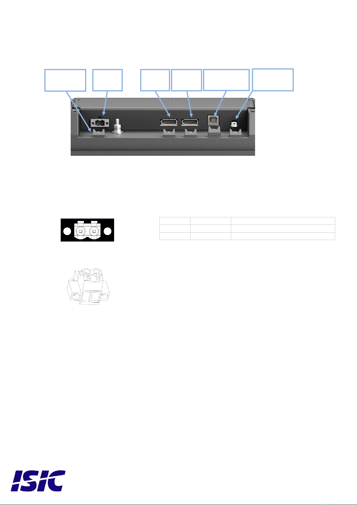
3.1 24VDC SUPPLY.......................................................................................................................................................................... 8
3.1.1 Models with 24VDC (18-36VDC) supply voltage.............................................................................................................. 8
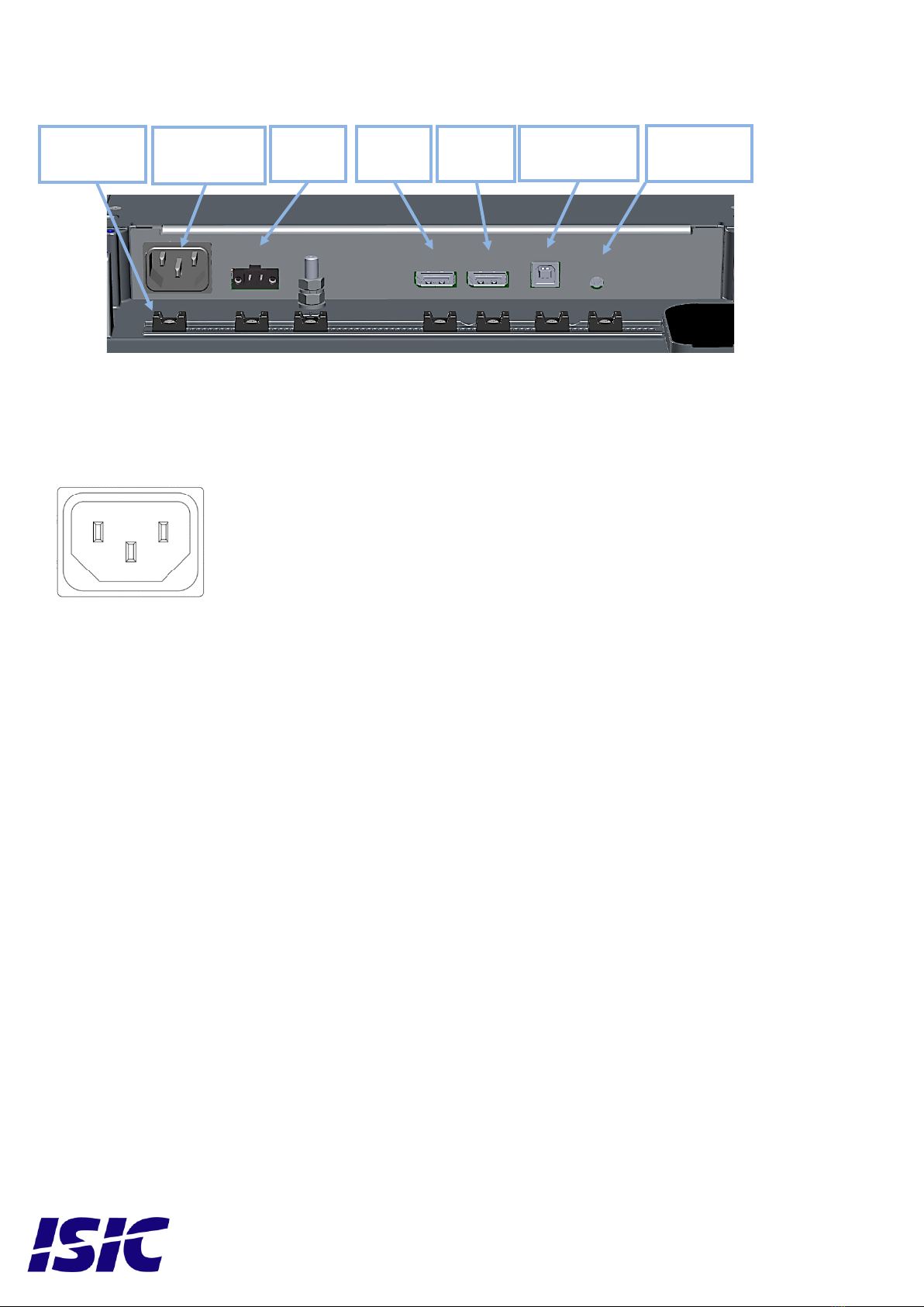
3.2 110/230VAC SUPPLY................................................................................................................................................................. 9
3.2.1 Models with 110/230VAC supply voltage .......................................................................................................................... 9
3.3 DISPLAYPORT 1.2 (DP) RECEPTACLE....................................................................................................................................... 10
3.4 USB TYPE BRECEPTACLE ....................................................................................................................................................... 10
3.5 2.5 MM JACK (RESERVED FOR FUTURE USE).............................................................................................................................. 10
4 TECHNICAL SPECIFICATIONS DURAMON10-24 S.......................................................................................................... 11
5 DURAMON S SERIES COMMUNICATION INTERFACE.................................................................................................. 11
5.1 VIRTUAL COM PORT............................................................................................................................................................... 11
5.2 DDC/CI VCP COMMAND ........................................................................................................................................................ 11
6 USB TOUCH................................................................................................................................................................................ 11
7 BUZZER....................................................................................................................................................................................... 11
8 DISPLAY BACKLIGHT LUMINANCE (DIMMING) ........................................................................................................... 12
8.1 BACKLIGHT LUMINANCE CONTROL.......................................................................................................................................... 12
8.2 DIMMING CURVE...................................................................................................................................................................... 12
9 ECDIS MODE.............................................................................................................................................................................. 12
9.1 ECDIS OPERATIONAL CONTROLS............................................................................................................................................. 12
9.2 ECDIS SETUP........................................................................................................................................................................... 12
10 DURAMON10-24 S LED INDICATORS................................................................................................................................ 13
10.1 LEDINDICATOR BEHAVIOR ................................................................................................................................................... 13
10.1.1 Status LED indicating color........................................................................................................................................... 13
10.1.2 Power LED indicating color.......................................................................................................................................... 13
10.2 OPTIONAL (CUSTOM)LED INDICATOR BEHAVIOR................................................................................................................. 13
10.2.1 Optional Status LED indicating color............................................................................................................................ 13
10.2.2 Optional Power LED indicating color........................................................................................................................... 13
11 FRONT PANEL CONTROLS.................................................................................................................................................. 14
11.1 TOUCH BUTTON INTERFACE.................................................................................................................................................... 14
11.2 OPTIONAL (CUSTOM)TOUCH BUTTON INTERFACE ................................................................................................................. 14
11.3 ON /STANDBY ....................................................................................................................................................................... 14
11.4 UP AND DOWN BUTTONS:.................................................................................................................................................... 15
11.5 ADVANCED OSD ................................................................................................................................................................... 15
12 TROUBLESHOOTING ............................................................................................................................................................ 15
13 SERVICING THE UNIT .......................................................................................................................................................... 15
14 TERMS, ACRONYMS AND ABBREVIATIONS.................................................................................................................. 15
15 ISIC INFO / SUPPORT............................................................................................................................................................. 16
16 REVISION HISTORY .............................................................................................................................................................. 17

User Reference Manual –DuraMON10-24 S Series
PN: 09330-000 Rev B Page 4
17 APPENDIX A: ADVANCED OSD MENU.............................................................................................................................. 18
17.1 INPUT SELECT......................................................................................................................................................................... 18
17.2 VGA ADJUSTMENTS.............................................................................................................................................................. 18
17.3 COLOR ADJUSTMENTS (NOT AVAILABLE IN ECDIS MODE) .................................................................................................... 20
17.4 ADVANCED COLOR (NOT AVAILABLE IN ECDIS MODE)......................................................................................................... 22
17.5 OSD SETTINGS....................................................................................................................................................................... 23
17.6 SYSTEM SETTINGS.................................................................................................................................................................. 24
18 APPENDIX B: PIXEL POLICY .............................................................................................................................................. 25

User Reference Manual –DuraMON10-24 S Series
PN: 09330-000 Rev B Page 5
1Features
Congratulations on your product purchase of DuraMON10-24 S series.
This short form manual is designed to get you started working with your new DuraMON10-24 S.
DuraMON10-24 S series of monitors are all made as rugged monitors especially designed for the demanding
operating conditions at sea.
The DuraMON10-24 S series are tested for full compliance to marine-standards IACS E10 and IEC 60945.
The monitor comes with excellent brightness and contrast levels that, together with wide viewing angles,
ensure high readability, making it very eye-friendly. For the best picture quality, always use a double
shielded cable with ferrites, like the one supplied with the monitor.
2 x DisplayPort
Feature control support for DDC/CI VCP commands via DisplayPort interface and USB interface
Dimming control (1cd to 100%)
Anti-Reflective coated cover glass
IP56 protected front, mounted in sealed console.
USB Touch (Optional)

User Reference Manual –DuraMON10-24 S Series
PN: 09330-000 Rev B Page 6
2General considerations at Installation and Operation
DuraMON10-24 S series are designed to work at conditions according to IEC 60945. However, keeping the
temperature and vibration level at a minimum will extend the lifetime of the product. ISIC recommend
operating this product at normal room temperature (20-25°C), with the lowest level of vibration and
humidity.
2.1 Installation
To obtain the best possible operating conditions, please note the following precautions.
-Cooling.
When mounting DuraMON10-24 S series in cabinet/console, please ensure that air can flow freely
around the product cabinet, to avoid any unnecessary rise in temperature. If it is not possible to
have an adequate natural airflow, please ensure forced airflow inside the console.
-Sunlight
If the unit can be exposed to direct sunlight, there is a potential risk that the unit can be
overheated. Please take measures to prevent direct sunlight. Do also consider forced cooling on
the back of the unit.
Please refer to Mechanical Outline for installation
2.1.1 Mechanical Outline
DuraMON 10 S: 09311-000
DuraMON 15 S: 09316-000
DuraMON 22 S: 11003-000
DuraMON 24 S: 11004-000
2.1.2 Desktop/Ceiling mounting kit with tilt
DuraMON 10 S: 09313-000
DuraMON 15 S: 09314-000
DuraMON 22 S: 10123-000
DuraMON 24 S: 10123-000
2.1.3 Console mounting kit (Sealing IP44):
DuraMON 10 S: 09353-000
DuraMON 15 S: 09354-000
DuraMON 22 S: 10064-000
DuraMON 24 S: 10065-000

User Reference Manual –DuraMON10-24 S Series
PN: 09330-000 Rev B Page 7
2.1.4 Compass safe distance
2.1.5 Power Consumption
Test object / condition
Pmax [W]
DC
Pmax [VA]
AC
DuraMON 10 S
12
-
DuraMON 15 S
21.4
-
DuraMON 22 S
44
44
DuraMON 24 S
46
46
In standby mode, the product will still consume power.
To cut off all power consumption, it is necessary to disconnect its supply power.
2.1.6 Inrush current
Test object / condition
Current[A] @ 24VDC
DuraMON 10 S
4
DuraMON 15 S
5
DuraMON 22 S
10
DuraMON 24 S
10
Test object / condition
Current[A] @ 115VAC
Current[A] @ 230VAC
DuraMON 10 S
N/A
N/A
DuraMON 15 S
N/A
N/A
DuraMON 22 S
55A
100A
DuraMON 24 S
55A
100A
2.2 Operation
2.2.1 Warm up
To obtain correct display colors and luminance, a warm-up period of minimum 30 minutes is required.
Test object / condition
Minimum Compass
safe distance [cm]
(5.4°/H deviation or a
horizontal magnetic
flux of 0.094µT)
Minimum Compass safe
distance [cm]
(18°/H deviation or a
horizontal magnetic flux
of 0.313µT)
DuraMON 10 S
95
60
DuraMON 15 S
110
70
DuraMON 22 S
185
120
DuraMON 24 S
205
140

User Reference Manual –DuraMON10-24 S Series
PN: 09330-000 Rev B Page 8
3DuraMON10-24 S connections
3.1 24VDC supply
3.1.1 Models with 24VDC (18-36VDC) supply voltage
24 VDC: Nominal input voltage. Galvanic marine isolated with reverse polarity protection.
18-36VDC: Operating voltage range.
Mating part: Weidmüller BLZP5.08HC/02/180F
Tool: 0.6x3.5mm slotted (flat headed) screwdriver
Terminal
Connection
Wire compliance
1
0VDC
Multicore AWG16-12 (1-4 mm2)
2
+24VDC
Multicore AWG16-12 (1-4 mm2)
2.5 mm Jack
(Aux)
DP 2
DP 1
USB Type B
(Hub)
24VDC
-+
1 2
Support for
cable straps

User Reference Manual –DuraMON10-24 S Series
PN: 09330-000 Rev B Page 9
3.2 110/230VAC supply
3.2.1 Models with 110/230VAC supply voltage
115 / 230 VAC: Nominal input AC voltage.
90 - 264 VAC: Operating AC voltage range.
47 - 63 Hz: Operating frequency range
IEC plug type C14
Mating connector: IEC type C13
2.5 mm Jack
(Aux)
DP 2
DP 1
USB Type B
(Hub)
24VDC
Support for
cable straps
115/230VAC
N L
PE

User Reference Manual –DuraMON10-24 S Series
PN: 09330-000 Rev B Page 10
3.3 DisplayPort 1.2 (DP) receptacle
Mating part: Male full size DisplayPort connector
with mechanical latch.
Note! Only use DisplayPort cables with pin 20 unconnected
3.4 USB Type B receptacle
Mating part: Plug USB type B
3.5 2.5 mm jack (reserved for future use)
Mating part: 2.5 mm Jack for half duplex RS-485
Pin
Description
1
ML_Lane 0 (p)
2
GND
3
ML_Lane 0 (n)
4
ML_Lane 1 (p)
5
GND
6
ML_Lane 1 (n)
7
ML_Lane 2 (p)
8
GND
9
ML_Lane 2 (n)
10
ML_Lane 3 (p)
11
GND
12
ML_Lane 3 (n)
13
CONFIG1
14
CONFIG 2
15
AUX CH (p)
16
GND
17
AUX CH (n)
18
Hot plug
19
Return
20
DP_PWR
Pin
Description
1
VBUS (+5V)
2
Data-
3
Data+
4
GND
Pin
Description
1
5VDC (Only for ISIC
applications)
2
RS-485 A
3
RS-485 B
4
GND

User Reference Manual –DuraMON10-24 S Series
PN: 09330-000 Rev B Page 11
4Technical specifications DuraMON10-24 S
Please refer to datasheet for the purchased variant
DuraMON 10 S: 09328-000
DuraMON 15 S: 09329-000
DuraMON 22 S: 10066-000
DuraMON 24 S: 10067-000
5DuraMON S Series Communication Interface
DuraMON S series supports 2 types of communication protocols
DDC/CI VCP command via DisplayPort
Virtual Serial Communication via USB interface.
5.1 Virtual COM Port
Please refer to Serial Communication Protocol 04924-002
The type of the product can be queried by sending the ‘TYP’ command to the Virtual COM Port.
Monitor
Response from monitor
DuraMON 10 S
DM101
DuraMON 15 S
DM156
DuraMON 22 S
DM215S
DuraMON 24 S
DM238S
5.2 DDC/CI VCP Command
Please refer to DDC/CI VCP Command protocol 09370-002.
6USB Touch
For models ordered with multitouch only:
Monitors with optional multi-PCAP touch sensor comply with Windows 8 (or newer) standard USB HID drivers.
Linux operating systems might come with the HID driver as part of the Linux kernel, compatibility is not
guaranteed.
7Buzzer
For models ordered with Buzzer only:
Buzzer can be activated by serial command, please refer to Serial Communication Protocol 04924-002

User Reference Manual –DuraMON10-24 S Series
PN: 09330-000 Rev B Page 12
8Display backlight luminance (Dimming)
8.1 Backlight Luminance control
Display luminance can be controlled by Communication interfaces.
For models with front panel controls: please refer to section 11.4 UP and DOWN buttons
8.2 Dimming curve
The dimming curve is 12-bit squared from 1 cd to maximum brightness for display.
9ECDIS mode
For ECDIS models only
To obtain correct display colors and luminance, a warm-up period of minimum 30 minutes is required.
Be aware that use of the backlight, brightness, or contrast controls in ECDIS mode may inhibit visibility of
information particularly at night!
9.1 ECDIS operational controls
All operational controls for radar, navigational systems and equipment must be operated from such systems
and equipment controls.
Warning: Operating the front panel control up or down touch button in will cause incorrect ECDIS backlight
setting, and the orange status indicator will illuminate as a warning. Pressing UP and DOWN together at the
same time will restore preset ECDIS backlight luminance
9.2 ECDIS setup
To setup ECDIS on the system a color token table must be downloaded from the monitor to the ECDIS
application.
USB interface: Please refer to Serial Communication Protocol 04924-002 for details.
DDC interface: Please refer to DDC/CI VCP Command protocol 09370-002 for details.

User Reference Manual –DuraMON10-24 S Series
PN: 09330-000 Rev B Page 13
10 DuraMON10-24 S LED indicators
The LEDs are not marked on the front and are only visible when activated.
LED brightness follows the LCD backlight setting.
10.1 LED indicator behavior
10.1.1 Status LED indicating color
Orange: Warning:
- Standby
- No signal
- Out of ECDIS mode (DAY/DUSK/NIGHT) (for ECDIS models only)
Green: In ECDIS mode DAY/DUSK/NIGHT (for ECDIS models only)
No light: OK - Normal operation
10.1.2 Power LED indicating color
Blue: Power is connected to the product.
No blue light: No power
10.2 Optional (Custom) LED indicator behavior
10.2.1 Optional Status LED indicating color
Orange: “Warning”
- Standby
- No signal
- Out of ECDIS range (DAY/DUSK/NIGHT) (for ECDIS models only)
Green: N/A
LCD image + No light: OK - Normal operation
no LCD image + No light: No power
10.2.2 Optional Power LED indicating color
Blue: N/A
Power
Status

User Reference Manual –DuraMON10-24 S Series
PN: 09330-000 Rev B Page 14
11 Front panel controls
For models with front panel touch button interface only.
Please refer to disclaimer on page 2.
11.1 touch button interface
The front panel control icons are illuminated and will follow the brightness level of the monitor backlight
luminance.
11.2 Optional (Custom) touch button interface
11.3 On / Standby
When no input signals are detected, the screen will display “No signal” for 15 sec and enter standby mode.
When the input signal is detected, the screen will turn on again.
For models with front panel controls only:
Warning: (For ECDIS models only) the Standby button should not be operated in ECDIS mode. All
controls should be handled from the radar, navigational systems, and equipment.
On, press the standby button to activate the monitor and backlight.
Standby can be activated by pressing the button for 5 seconds.
No signal
Back
Select
Down
Up
On / Standby
Down
Up

User Reference Manual –DuraMON10-24 S Series
PN: 09330-000 Rev B Page 15
11.4 UP and DOWN buttons:
Warning: (For ECDIS models only) Operating the front panel control up or down touch button in will cause
incorrect ECDIS backlight setting, and the orange status indicator will illuminate as a warning. Pressing UP
and DOWN together at the same time will restore preset ECDIS backlight luminance
UP and DOWN buttons will adjust the monitor backlight luminance.
11.5 Advanced OSD
With the Advanced OSD (On Screen Display) you can modify the settings and control the special
features of the DuraMON as described in Appendix A.
Advanced OSD can be operated by Communication Interfaces.
For models with front panel controls “Back” and “Select” interfaces only:
To enter the Advanced OSD, press both the “Back” and “Select” buttonss at the same time.
To navigate the Advanced OSD use the “Up” and “Down” buttons and press “Select” to select a
specific setting. To get back to the previous menu point, press the “Back” button.
12 Troubleshooting
Problem
Cause
Solutions
No picture on display
Backlight luminance set to
minimum
Increase backlight
No picture on display
Monitor turned off
Turn on the monitor
No picture on display
No input signal present
Apply signal
No picture on display
No power cord connected
Apply power
The unit will not turn on.
Unknown
Please do not try to open the
unit. Send it to ISIC A/S for
repair.
13 Servicing the unit
In case the unit still fails after following the troubleshooting send the unit to ISIC for repair. There are no user
serviceable parts inside and to ensure ECDIS compliance the monitor must be recalibrated at ISIC.
14 Terms, Acronyms and abbreviations
OSD:
On Screen Display

User Reference Manual –DuraMON10-24 S Series
PN: 09330-000 Rev B Page 16
15 ISIC info / Support
In case you have inquiries or problems with your DuraMON10-24 S, you have a number of possibilities to get
support.
Company name: ISIC A/S
Head office: Edwin Rahrs Vej 54
DK –8220 Brabrand
Denmark
Shipping address: Holmstrupgaardvej 5
DK-8220 Brabrand
Denmark
Telephone: +45 70 20 70 77
Email: isic@isic-systems.com
www: www.isic-systems.com
VAT number: DK 16 70 45 39
Bank Address: Handelsbanken A/S
Havneholmen 29
DK-1561 København V
Denmark
Bank Code: 0892
IBAN DKK: DK53 0892 0001 0159 69
IBAN EUR: DK48 0892 0003 0026 19
IBAN USD: DK26 0892 0003 0026 27
SWIFT: HANDDKKK
Contacts:
RFQ’s: By mail to sales@isic-systems.com
Orders: By mail to orders@isic-systems.com
Support: Via homepage www.isic-systems.com under aftersales
By mail to service@isic-systems.com
During office-hours (Mo-Fr: CET 0800 - 1500) at +45 70 20 70 77
Service: Before shipment for service Request Return Material Authorization number at
homepage https://isic-systems.com/after-sales/tech-support-rma/
By mail to service@isic-systems.com

User Reference Manual –DuraMON10-24 S Series
PN: 09330-000 Rev B Page 17
16 Revision history
Rev 0
April 2021
Preliminary
Rev A
June 2021
First release
Rev B
September 2023
adding DuraMON 22 S + DuraMON 24 S (with front panel controls and
ECDIS) and VA data

User Reference Manual –DuraMON10-24 S Series
PN: 09330-000 Rev B Page 18
17 Appendix A: Advanced OSD Menu
With the Advanced OSD (On Screen Display) you can modify the settings and control the special
features of the DuraMON
Advanced OSD can also be operated by Communication Interfaces.
For models with front panel controls “Back” and “Select” interfaces only:
To enter the Advanced OSD, press both the “Back” and “Select” buttons at the same time.
To navigate the Advanced OSD use the “Up” and “Down” buttons and press “Select” to select a
specific setting. To get back to the previous menu point, press the “Back” button.
17.1 Input select
Input Select –Main Picture Channel
Input Select –Scan Input
Main Menu
Input Select
VGA Adjustments
Color Adjustments
Advanced Color
Custom info
OSD Settings
System Settings
Input Select
Main Picture Channel
VGA
DVI
DP
The Main Picture Channel
can be selected between
all available inputs (VGA,
Display Port and DVI.
Main Menu
Input Select
VGA Adjustments
Color Adjustments
Advanced Color
Custom info
OSD Settings
System Settings
Input Select
Main Picture Channel
Scan Input
Scan Input
On
Off
Scans Inputs for active
source.
Default is On.
17.2 VGA Adjustments
Image Adjustments –Auto Adjust
Image Adjustments –Clock
Main Menu
Input Select
VGA Adjustments
Color Adjustments
Advanced Color
Custom info
OSD Settings
System Settings
VGA Adjustments
Auto Adjust
Clock
Phase
Hor. Position
Ver. Position
Selecting auto adjust will
force the system to adjust
the image (clock, phase,
bandwith and position)
Main Menu
Input Select
VGA Adjustments
Color Adjustments
Advanced Color
Custom info
OSD Settings
System Settings
VGA Adjustments
Auto Adjust
Clock
Phase
Hor. Position
Ver. Position
The pixel clock for VGA
can be selected here.

User Reference Manual –DuraMON10-24 S Series
PN: 09330-000 Rev B Page 19
Auto Adjust
Auto Adjust
Clock
MIN MAX
Value
Image Adjustments –Phase
Image Adjustments –Hor. Position
Main Menu
Input Select
VGA Adjustments
Color Adjustments
Advanced Color
Custom info
OSD Settings
System Settings
VGA Adjustments
Auto Adjust
Clock
Phase
Hor. Position
Ver. Position
Phase
MIN MAX
Value
The phase of the display
can be set for VGA.
Main Menu
Input Select
VGA Adjustments
Color Adjustments
Advanced Color
Custom info
OSD Settings
System Settings
VGA Adjustments
Auto Adjust
Clock
Phase
Hor. Position
Ver. Position
Hor. Position
MIN MAX
Value
The horizontal position of
the picture can be set
here.

User Reference Manual –DuraMON10-24 S Series
PN: 09330-000 Rev B Page 20
Image Adjustments –Vert. Position
Main Menu
Input Select
VGA Adjustments
Color Adjustments
Advanced Color
Custom info
OSD Settings
System Settings
VGA Adjustments
Auto Adjust
Clock
Phase
Hor. Position
Ver. Position
Ver. Position
MIN MAX
Value
The vertical position of the
picture can be set here.
17.3 Color adjustments (not available in ECDIS mode)
Color Adjustment –Backlight
Color Adjustment –Brightness
Main Menu
Input Select
VGA Adjustments
Color Adjustments
Advanced Color
Custom info
OSD Settings
System Settings
Color Adjustments
Backlight
Brightness
Contrast
Saturation
Hue
Auto Color Adjust
Backlight
MIN MAX
Value
It is possible to set the
backlight level.
Default is 50%.
Unless popups or OSD is
present it is possible to
press the “UP” or “DOWN”
button to adjust the
backlight level and then
press “ENTER” afterwards.
Main Menu
Input Select
VGA Adjustments
Color Adjustments
Advanced Color
Custom info
OSD Settings
System Settings
Color Adjustments
Backlight
Brightness
Contrast
Saturation
Hue
Auto Color Adjust
Brightness
MIN MAX
Value
It is possible to set the
brightness level.
Default is 50%.
This manual suits for next models
4
Table of contents
Other ISIC Marine Equipment manuals