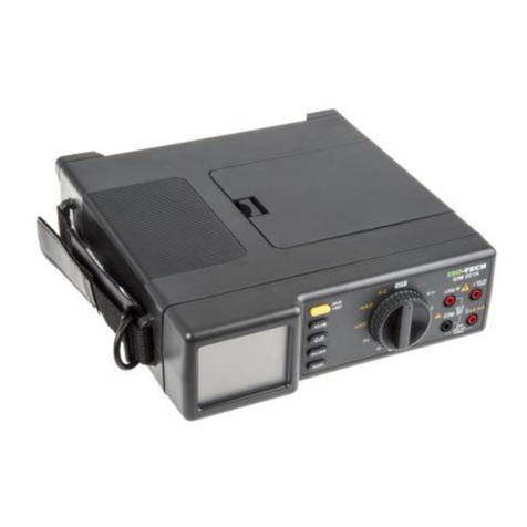
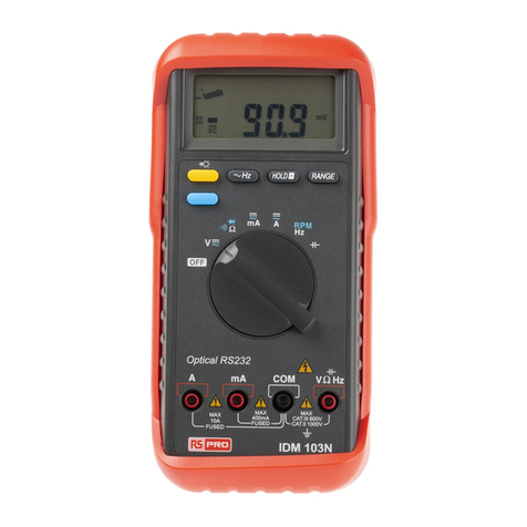
Isotech IDM 507 User manual

IDM 507
Instruction Manual
IDM 507
Process Multimeter
EN

1
Warning
. . . . . . . . . .
. . . . . . . . . .
. . . . . . . . . .
. . . . . . . .
Safety sheet
. . . . . . . . .
. . . . . . . . . .
. . . . . . . . . .
. . . . . . . .
. . . . . . . . .
Read First
Safety Information
Understand and follow operating instructions carefully.
Use the meter only as specified in this manual; otherwise,
the protection provided by the meter may be impaired.
WARNING
Identifies hazardous conditions and actions that could cause
BODILY HARM or DEATH.
CAUTION
Identifies conditions and actions that could DAMAGE the meter
or equipment under test.
WARNING
˙When using test leads or probes, keep your fingers behind
the finger guards.
˙Remove test lead from Meter before opening the battery
door or Meter case.
˙Use the Meter only as specified in this manual or the
protection by the Meter might be impaired.
˙Always use proper terminals, switch position, and range for
measurements.
˙Verify the Meter’s operation by measuring a known voltage.
If in doubt, have the Meter serviced.
˙Do not apply more than the rated voltage, as marked on
Meter, between terminals or between any terminal and
earth ground.
˙Only replace the blown fuse with the proper rating as
specified in this manual.
˙Use caution with voltages above 30 Vac rms, 42 Vac peak,
or 30 Vdc. These voltages pose a shock hazard.
˙To avoid false readings that can lead to electric shock and
injury, replace battery as soon as low battery indicator.
˙Disconnect circuit power and discharge all high-voltage
capacitors before testing resistance, continuity, diodes, or
capacitance.
˙Do not use Meter around explosive gas or vapor.
˙To reduce the risk of fire or electric shock do not expose this
product to rain or moisture.
˙Do not touch any circuits or parts of circuits if they may be
subject to voltages higher than 30VAC rms or 30VDC.
Warning Safety sheet

2
Risk of electric shock
See instruction manual
AC measurement
DC measurement
Equipment protected by double or reinforced insulation
<Battery
Fuse
Earth
Conforms to EU directives
Do not discard this product or throw away
CAUTION
˙Disconnect the test leads from the test points before chang-
ing the position of the function rotary switch.
˙Never connect a source of voltage with the function rotary
switch in , A, Loop-Power position.
˙Do not expose Meter to extremes in temperature or high
humidity.
˙Never set the meter in , A, Loop-Power function to
measure the voltage of a power supply circuit in equipment
that could result in damage the meter and the equipment
under test.
Symbols as marked on the Meter and Instruction manual
Unsafe Voltage
To alert you to the presence of a potentially hazardous voltage,
when the Tester detects a voltage ≧30 V or a voltage
overload (OL) in V, mV . The ”“ symbol is displayed and High
voltage indicator is turned on.
Maintenance
Do not attempt to repair this Meter. It contains no user service-
able parts. Repair or servicing should only be performed by
qualified personnel.
Cleaning
Periodically wipe the case with a dry cloth and detergent.
Do not use abrasives or solvents.

3
The Meter Description
Front Panel Illustration
1. LCD display: 50,000 counts.
2. Push buttons for features.
3. Rotary switch for turn the power on / off and select the
function.
4. Input terminal for A function / Loop-Power mode +/ source
mode +.
5. Input terminal for mA function / Loop-Power mode -/ source
mode -/ simulate mode +.
6. Input terminal for V / / Diode / Hz functions.
7. Common (Ground reference) input terminal for all functions.

4
Making Basic Measurements
Preparation and Caution Before Measurement
: Observe the rules of Warnings and Cautions
When connecting the test leads to the DUT (Device Under Test)
connect the common (mA) test lead before connecting the live
lead; when removing the test leads, remove the test live lead
before removing the common test lead.
The figures on the following pages show how to make basic
measurements.
Auto / Manual Test
˙ When switch rotary in V / mV / A position, press the Function
button > 1sec to enter auto test mode. In this mode, the meter
showed the indication “AUTO TEST” on the display.
˙ Press the Function button that you can change to manual test
mode from auto test mode.
˙ When the meter In auto test mode, it will automatically detect
the input signal and determine. Then it will show the suitable
result on the display.
˙ In manual test mode, you can press the Function button to
select the measuring function.
Auto / Manual Range
˙ In a complex range of measuring function, you can start the
auto range mode. This mode can automatically detect the
input signal and determine. Then it will show the suitable result
on the display.
˙When press the RANGE button > 1sec, you can enter auto
range mode. In this mode, the meter shows the indication
“AUTO RANGE” on the display.
˙Press the RANGE button that you can change to manual
range mode from auto range mode.
˙In manual range mode, you can press the RANGE button to
select the measuring range.

5
Measuring Voltage
˙ Press the Function button to select the presently measuring
function (AC / DC / AC+DC).
˙ Press the Function button > 1 sec to enter the auto test
mode, and press again to exit this mode.
˙The auto test mode can automatically determine the
voltage / current which is AC or DC.
˙ The AC+DC mode is defined by . 22 DCAC

6
Measuring Current
˙ The basic operations are same as voltage function.
Measuring Frequency
˙When measuring voltage or current, press the Hz button to
measuring the frequency for voltage or current.
˙ Press the Hz button again to exit this mode.
High Frequency Reject (Low Pass Filter)
˙ When measuring voltage or current, press the HFR button to
equip with low pass filter.
˙ Press the HFR button again to exit this mode.
˙ The cut-off frequency (-3dB point) is at 800Hz.

7
Measuring Resistance
˙ Press the Function button to select the presently measuring
function (/ Continuity Check / Diode Test).
Continuity Check
˙ Press the Function button to select continuity check when
the rotary in resistance position.
˙ The buzzer allows you to quickly continuity tests without
watching the display.
˙The buzzer sounds when a short (< 30) is detected.

8
Diode Test
˙ Press the Function button to select diode test when the
ro-tary in resistance position.
˙ In diode test, you can test direction and forward voltage.
˙ If the DUT was not a diode (Open, Short, Resistance or
Capacitance), the display showed “-----”.

9
DC Current Output
˙To use the DC current output function, turn the rotary in output
position (Adjustable DC output or Auto DC output).
˙The DC current output function has both modes: Source Mode
& Simulate Mode
˙The output mode has both types: 0-20mA & 4-20mA. That is
selectable. When power on, press the RANGE button to
select. And the selection was set to default.
Adjustable DC Current Output
˙To use the adjustable DC current output function, turn
the rotary in adjustable output position (
˙ In this function, you can adjust the DC current output.
˙ %STEP: 0% / 25% / 50% / 75% / 100% / 120% / 125%
˙ Fast Setup: 0% / 50% / 100%
˙ Fine Setup : Minimum resolution 1uA, 0mA to 24mA
% STEP 0-20mA Mode 4-20mA Mode
0% 0mA 4mA
25% 5mA 8mA
50% 10mA 12mA
75% 15mA 16mA
100% 20mA 20mA
120% 24mA N/A
125% N/A 24mA
Auto DC Current Output
˙To use the auto DC current output function, turn the rotary in
auto output position (
˙ In this function, you can press the BLUE button to
select 4 kinds of the auto DC current output.
˙ Press the HOLD button to pause / continue the output.
Mode Type Action
Linear 0% to 100% to 0% per 40 sec
Linear 0% to 100% to 0% per 20 sec
25% Step 0% to 100% to 0%, a step per 15 sec
25% Step 0% to 100% to 0%, a step per 5 sec
)
)

10
Source Mode
˙ When meter in the source mode, it provided internal power
supply (Batteries > 4.5V) to drive the DC current output.
˙ To operate in the source mode, put the both probes in A
terminal (Source +) and mA terminal (Source -). Then the
meter will automatically enter the source mode.
˙ Do not turn the rotary when the probe in the A terminal. This
action maybe caused > 30mA to pass through the loop
circuit.
˙ The source mode can work in both modes: Adjustable DC
output & Auto DC output
˙ In auto DC current output mode, you can press the HOLD
button to pause / continue the output.

11
Simulate Mode
˙ When meter in the simulate mode, it used external power
supply (12V to 48V) to drive the DC current output.
˙ To operate in the simulate mode, put the both probes in mA
terminal (Simulate +) and COM terminal (Simulate -).
Then the meter will automatically enter the simulate mode.
˙Do not turn the rotary when the probe in the A terminal.
This action maybe caused > 30mA to pass through the loop
circuit.
˙ The simulate mode can work in both modes: Adjustable DC
output & Auto DC output.
˙ In auto DC current output mode, you can press the HOLD
button to pause / continue the output.

12
Loop Power
˙ In this function, the meter provided internal power supply to
output > 24V / 20mA.
˙ To operate in the loop power function, put the probes in A
terminal (Source +) and mA terminal (Source -). Then the
meter will automatically drive.
˙Do not turn the rotary when the probe in the A terminal. This
action maybe caused > 30mA to pass through the loop
circuit.
250Hart
˙ When switch rotary in loop power position, press the Function
button to equip with 250Hart.
˙ Press the Function button again to strip 250Hart.

13
Auto Hold
˙ Press the A-HOLD button to start the auto hold mode, and
press again to exit.
˙ In this mode, the meter show the indication “HOLD” on the
display.
˙ When the difference is bigger (> 50d) than hold data, and it
is also stable. Then the meter will automatically hold a new
data on the display.
˙ When the reading is smaller the limit, the auto hold mode is
not working.
Function Limit
V < 0.1V
mV < 1mV
others No Limit
Relative
˙ Press the REL button to start relative mode. The meter
remembers the presently reading as reference and shows
the indication “” on the display.
˙In this mode, the meter deducts the reference from each
reading, and shows the result on the display.
˙ Press the REL button to select display (Reference or
Result). The indication “” blinks on the display when it shows
the result.
˙ Press the REL button > 1sec to exit this mode.
Maximum / Minimum / Average
˙ When blink cursor of menu is MAX / MIN / AVG, press the
ENTER button to start MAX / MIN / AVG mode.
˙In this mode, the meter records each data to compare the
maximum and minimum. And calculate the average.
˙ You can move the blink cursor of menu to select what was
showed on the display.
˙ Press the CANCEL button to exit this mode.

14
Store / Recall
˙ When blink cursor of menu is STORE, press the ENTER
button to store the presently reading to memory.
˙ The meter can store maximum 100 data in the memory.
˙ You can enter the recall mode to review the stored data.
˙ When blink cursor of menu is RECALL, press the ENTER
button to start recall mode.
˙ In the recall mode, you can press the UP or DOWN button to
review the stored data. When press it > 1sec, you can fast
search.
˙ Press the CANCEL button to exit this mode.
˙ To clear all data of stored function in memory, see the Power
On Options.
Auto Power Off
˙ If there is no any action in the meter, then the meter will
automatically turn off to save the power of batteries.
˙The APO time is default 20 minutes.
˙ When the meter was power on, the APO was set to default.
To disable the APO, see the Power On Options.
Auto Backlight
˙ The backlight is automatically turned on at dark
environment.
˙ When the meter was power on, the auto backlight was set to
default. To disable the automatic, and enable / disable the
backlight, see the Power On Options.
Buzzer
˙ Equip 2kHz tone buzzer.
˙ Valid button press: Beep once
˙ Invalid button press: Beep twice
˙To enable / disable the buzzer, see the Power On Options.

15
Power On Options
When turn the power on, press the function button to execute
the below options.
Button Action
RANGE Select the output type (0-20mA & 4-20mA)
and set it to default.
FUNCTION Disable APO.
HFR Show the firmware version.
ENTER Enable / Disable the buzzer and set the
option to default.
CANCEL Clear all data of stored function in memory.
A-HOLD Enable backlight & disable automatic.
REL Disable backlight & disable automatic.

16
Battery and Fuse Replacement
Refer to the following figure to replace fuse and the batteries :
˙ Be always replaced the batteries & fuse that conform the
specifications.
˙ Battery Type: 4 x 1.5V IEC LR6 or AA size
˙ Fuse Type: 2 x 440mA, 1000V IR 10kA Fuse (Bussmann
DMM-B-44/100)
˙ When the battery low indication “ ” was showed on the
display, replace the batteries.
˙To save the power of batteries, you can disable the Auto
Backlight and Buzzer. See the Power On Options on how
to disable both functions. Besides, always use the simulate
mode on the DC current output mode.
˙ To check the fuse, use the other meter to inspect it.

17
Specifications
General Specifications
Maximum voltage applied to any terminal :
1000VDC or 1000VAC rms
Display : 50,000 counts, over range to 110%.
Polarity Indication :
Automatic, positive implied, negative indicated.
Over Range Indication : OL
Measuring Rate : 10 samples per second
Power Requirements : 4 x 1.5V IEC LR6 or AA size
Battery Life: 100 hours
Low Battery Indication : “ ” is displayed when the
batteries voltage drops below operating voltage.
Low Battery Voltage: Approx 4.5V
Auto Power Off: Default 20 minutes.
Operating Ambient : -10°C to 30°C (< 85% RH),
30°C to 40°C (< 75% RH),
40°C to 50°C (< 45% RH)
Storage Temperature :
-20°C to 60°C, 0% RH to 80% RH (batteries not fitted)
Temperature Coefficient :
0.1 x (Specified Accuracy) / °C, < 18°C or > 28°C
Operating Altitude : 6561.7ft (2000m)
Calibration Cycle : 1 time per year
Weight : 630g including battery.
Dimensions (W x H x D) : 95 x 207 x 52 (mm) with holster.
Accessories :
Batteries, test leads, user manual & software CD.
Safety : Complies with EN 61010-1, EN 61010-2-030
CAT IV 600V, CAT III 1000V
ⅠThe circuits not connected to mains.
ⅡThe circuits directly connected to Low-voltage
installation.
ⅢThe building installation.
ⅣThe source of the Low-voltage installation.
EMC : EN 61326-1, EN 61326-2, EN 55011, EN 61000-4
Pollution Degree : 2
Shock Vibration : 5Hz to 55Hz, 3g max
Sinusoidal vibration for MIL-PRE-28800F class 2.
Drop Protection : 5ft (1.5m)
Indoor Use

18
Electrical Specifications
˙ Accuracy is ± (% reading + number of digits)
˙ Ambient temperature: 23°C ± 5°C (< 80% RH)
˙ For the best measurements, with REL function to
compensate for offsets.
1. Voltage
Function Range Accuracy
AC[1]
50.000mV
500.00mV
Sine Wave:
± (0.7% + 20d) for 40Hz to 70Hz
± (1.5% + 40d) for 71Hz to 10kHz
5.0000V
50.000V
500.00V
1000.0V[2]
Sine Wave:
± (0.5% + 20d) for 40Hz to 70Hz
± (1.5% + 40d) for 71Hz to 1000Hz
± (3.0% + 80d) for 1001Hz to 10kHz
DC
50.000mV ± (0.05% + 30d)
500.00mV
5.0000V
50.000V
500.00V
1000.0V
± (0.05% + 5d)
[1] Below 5% of AC range, add 20d to accuracy.
[2] The bandwidth of range is 40Hz to 1kHz.
Input Protection : 1000VDC or 1000VAC rms
Input Impedance : 10M, < 100pF
Bandwidth : 40Hz to 10kHz
Minimum Resolution : 1µV in the 50mV range
CMRR / NMRR (Common / Normal Mode Rejection Ratio) :
VAC: CMRR > 60dB at DC, 50Hz / 60Hz
VDC: CMRR > 100dB at DC, 50Hz / 60Hz
NMRR > 50dB at DC, 50Hz / 60Hz
AC Conversion Type :
AC conversions are ac-coupled, true rms responding,
calibrated to the sine wave input.
For non-sine wave add the following Crest Factor corrections :
For Crest Factor of 1.4 to 2.0, add 1.0% to AC accuracy.
For Crest Factor of 2.0 to 2.5, add 2.5% to AC accuracy.
For Crest Factor of 2.5 to 3.0, add 4.0% to AC accuracy.
AC+DC Accuracy : AC accuracy + DC accuracy + 1.0%
HFR Accuracy : AC accuracy + 1.0% for 40Hz to 400Hz
The Cut-Off Frequency of HFR : 800Hz (-3dB point)
Attenuation Characteristic of HFR : Approx -24dB

19
2. Current
Function Range Accuracy
AC[1] 50.000mA
1.000A
Sine Wave:
± (1.0% + 20d) for 40Hz to 70Hz
± (2.0% + 40d) for 71Hz to 10kHz
DC 50.000mA
1.000A ± (0.05% + 5d)
[1] Below 5% of AC range, add 20d to accuracy.
Input Protection : Equipped with High Energy Fuse.
440mA, 1000V IR 10kA Fuse (Bussmann DMM-B-44/100)
Input Impedance :
0.1at A input, 13at mA input. Not contain protection circuit.
Bandwidth : 40Hz to 10kHz
Minimum Resolution : 1µA in the 50mA range
Maximum Measuring Time :
1 minutes at A input, 10 minutes at mA input.
Rest time is 20 minutes minimum.
AC Additional Specifications :
The AC additional specifications are same as voltage.
3. Frequency Counter
Range Resolution Accuracy
500.00Hz 0.01Hz
± 3d
5.0000kHz 0.1Hz
50.000kHz 1Hz
100.00kHz 10Hz
Input Protection : 1000VDC or 1000VAC rms
Minimum Frequency : 5Hz
4. Frequency Counter Sensitivity
Function Range Sensitivity (Peak-to-Peak)
5 to 10k (Hz) 10k to 100k (Hz)
mV 50.000mV
500.00mV 10mV 100mV
V
5.0000V 1V 1V
50.000V
500.00V
1000.0V 1V
Unspecified
A50.000mA 10mA
1.000A 300mA
Table of contents
Other Isotech Multimeter manuals

Isotech
Isotech IDM 91E User manual

Isotech
Isotech ICM A7-4 User manual

Isotech
Isotech IDM 98-III User manual

Isotech
Isotech IDM 97 User manual

Isotech
Isotech ICM A9 User manual

Isotech
Isotech IDM 103N User manual

Isotech
Isotech IDM99II User manual

Isotech
Isotech IDM17 User manual

Isotech
Isotech IDM 205 RMS User manual

Isotech
Isotech ICM36R User manual

Isotech
Isotech IDM201N User manual

Isotech
Isotech IDM61 User manual

Isotech
Isotech ICM33R II User manual

Isotech
Isotech IDM19 User manual
Isotech
Isotech IDM 91E User manual

Isotech
Isotech IDM 98-III User manual
Isotech
Isotech IDM63N User manual

Isotech
Isotech IDM97II User manual

Isotech
Isotech IDM5 User manual
Isotech
Isotech IDM93N User manual