ITL PULSAR ILS-1400 Service manual

Toll Free: +1 (866) 624-8309 www.itl-llc.com
Installation
Instruction Manual
ILS-1400
ILS-2400
ILS-3400
ILS-3800
ILS Strobe
Lighting Systems
P
U
L
S
A
R
(XENON Series)

ILS Strobe Lighting Systems
DOC-3400-MNL Rev23.doc (9/22/2021) Copyright 2007-2021 ITL, LLC Page 2 of 86
Front Matter
Copyright & Trademarks
Copyright © 2007-2021 by ITL, LLC. All rights reserved. This document contains
proprietary information, photographs, graphics, and other material (collectively, "the
Content") protected by copyright, and this manual and all accompanying hardware,
software and documentation are copyrighted. No part of this document may be
photocopied or reproduced by mechanical, electronic, or other means in any form without
written consent of ITL, LLC.
ITL,LLC, ILS-1400, ILS-2400, ILS-3400, ILS-3800, ADP OnSite, ADP Lite, ADP Standard,
ADP Enterprise, and the ITL logo are trademarks of ITL, LLC. All other trademarks and
brand names are the property of their respective proprietors.
Limited Warranty and Disclaimer
ITL, LLC guarantees that every ILS-1400/2400/3400/3800 series strobe lighting system is
free from physical defects of design, materials and workmanship under normal use for
one (1) year from the date of installation or two (2) years from the date of shipment. If the
product proves defective during this warranty period it will be corrected by repair or
replacement f.o.b. factory. Please contact ITL, LLC in order to obtain a Return
Authorization Number, RMA.
In no event shall ITL, LLC’s liability exceed the price paid for the product from direct,
indirect, special, incidental, or consequential damages resulting from the use of the
product, its accompanying software, or its documentation. ITL, LLC makes no warranty
or representation, expressed, implied, or statutory, with respect to its products or the
contents or use of this documentation and all accompanying software, and specifically
disclaims its quality, performance, merchantability, or fitness for any particular purpose
unless otherwise stated.
The technical documentation is being delivered to you AS-IS. ITL, LLC makes no
warranty as to its accuracy or use. Any use of the technical documentation or the
information contained therein is at the risk of the user. Documentation may include
technical or other inaccuracies or typographical errors. ITL, LLC reserves the right to
revise or update its products, software, or documentation without obligation to notify any
individual or entity.
Please send any comments regarding the manual to [email protected].

ILS Strobe Lighting Systems
DOC-3400-MNL Rev23.doc (9/22/2021) Copyright 2007-2021 ITL, LLC Page 3 of 86
Safety Warning
This equipment uses lethal voltages which can cause serious injury and/or death. Do not
attempt to service this equipment with line power applied.
The strobe lamp used in this equipment produces brilliant flashes of light, which contain
ultraviolet radiation. Temporary or permanent eye damage may result if looking directly
at the strobe lamp while it is operating.
Do not rely on interlock switches or the bleeder circuit to remove lethal voltages from the
system. Always discharge all capacitors individually before servicing. Measure for
voltages using a voltmeter to ensure that power is off and has been completely removed.
Do not wear any jewelry. Gold and silver are excellent conductors of electricity.
Battery Warning and Disposal
There is danger of explosion if the included sealed lead-acid battery is replaced
incorrectly. Only replace the battery with the same or equivalent type recommended by
the battery manufacturer. Dispose of used batteries according to the battery
manufacturer's instructions.
Do not incinerate, disassemble, or puncture the battery.
For questions or details please contact The Battery Council International at (312) 664-
6610, or your local waste agency.

ILS Strobe Lighting Systems
DOC-3400-MNL Rev23.doc (9/22/2021) Copyright 2007-2021 ITL, LLC Page 4 of 86
Table of Contents
The fastest way to find a specific topic is to use the detailed index in the back of the
manual.
Front Matter ....................................................................................................................... 2
Copyright & Trademarks ................................................................................................ 2
Limited Warranty and Disclaimer ................................................................................... 2
Safety Warning .............................................................................................................. 3
Battery Warning and Disposal........................................................................................ 3
List of Illustrations and Tables ........................................................................................... 6
Introduction ........................................................................................................................ 8
Product Description ........................................................................................................... 9
Power Conversion, IPS-3400 ....................................................................................... 12
Flash head, IFH-1400/2400/3400 ................................................................................ 13
Specifications .................................................................................................................. 15
Environment ................................................................................................................. 15
Light Output ................................................................................................................. 15
Mechanical ................................................................................................................... 15
IFH-1400/2400 ......................................................................................................... 15
IFH-1700 (LED) (ILS-3800 only) ............................................................................... 15
IFH-3400 Flash Head ............................................................................................... 15
IPS-3400/3800 Power Supply .................................................................................. 15
Electrical ...................................................................................................................... 16
IPS-3400 .................................................................................................................. 16
IPS-3800 (ILS-3800 only) ......................................................................................... 16
Installation ....................................................................................................................... 17
Unpacking your Strobe Lighting System ...................................................................... 17
Tools for Installation ..................................................................................................... 17
Quick Installation Guide ............................................................................................... 17
Flash Head .................................................................................................................. 18
Leveling .................................................................................................................... 18
IFH-1400/2400 Flash Head Mounting ...................................................................... 20
IFH-3400 Flash Head Mounting ............................................................................... 25
Power Supply Grounding ............................................................................................. 32
Power Supply ............................................................................................................... 32
IPS-3400 Power Supply Mounting ............................................................................ 33
Power Transformer Input Voltage Wiring ................................................................. 39
PEC Mounting and Wiring ............................................................................................ 40
Circuit Boards .................................................................................................................. 51
1. ITL-3400-TRG Trigger Board ................................................................................... 51
A. LEDs and Caution Neon Light .............................................................................. 52
B. Switches............................................................................................................... 54
C. Hardware vs. Software Configuration .................................................................. 57

ILS Strobe Lighting Systems
DOC-3400-MNL Rev23.doc (9/22/2021) Copyright 2007-2021 ITL, LLC Page 5 of 86
E. Connectors ........................................................................................................... 58
2. ITL-3401-RLY Relay Board ...................................................................................... 59
3. ITL-3420-SEN / ITL-3421-SEN Sense Board........................................................... 60
4. ITL-3410-0HV High Voltage Board .......................................................................... 60
5. ITL-3451-RNC R/C Network Board .......................................................................... 62
Maintenance / Trouble-Shooting...................................................................................... 63
Recommended Tools ................................................................................................... 63
Maintenance ................................................................................................................ 64
Strobe Light Basics ...................................................................................................... 65
Three Essentials .......................................................................................................... 65
Input Power .................................................................................................................. 65
Day Circuit ................................................................................................................... 66
Night Circuit ................................................................................................................. 66
Discharge Circuit .......................................................................................................... 66
Trigger Circuit .............................................................................................................. 66
Measuring High Voltage ............................................................................................... 67
Measuring Side Light Voltage ...................................................................................... 67
Measuring Side Light Current ...................................................................................... 67
Measuring Capacitance ............................................................................................... 68
Troubleshooting Flowchart ........................................................................................... 69
WHITE Alarm ........................................................................................................... 69
RED Alarm ............................................................................................................... 70
SIDELIGHT Alarm .................................................................................................... 71
PEC Alarm LED ........................................................................................................ 72
No High Voltage ....................................................................................................... 73
Spare Parts & Replacement Parts ................................................................................... 74
Technical Support and Contact Info ................................................................................ 75
Contact Info ................................................................................................................. 75
RMA ............................................................................................................................. 75
Appendix ......................................................................................................................... 76
A – Lighting System ILS-3800 ..................................................................................... 76
Product Description .................................................................................................. 76
Installation ................................................................................................................ 77
Reference ........................................................................................................................ 83
Glossary ....................................................................................................................... 83
Schematic Symbols ..................................................................................................... 84
Index - Everything from A to Z ......................................................................................... 85

ILS Strobe Lighting Systems
DOC-3400-MNL Rev23.doc (9/22/2021) Copyright 2007-2021 ITL, LLC Page 6 of 86
List of Illustrations and Tables
Figure 1: ILS-1400 Red Strobe System ............................................................................. 9
Figure 2: ILS-2400 White Strobe System ........................................................................ 10
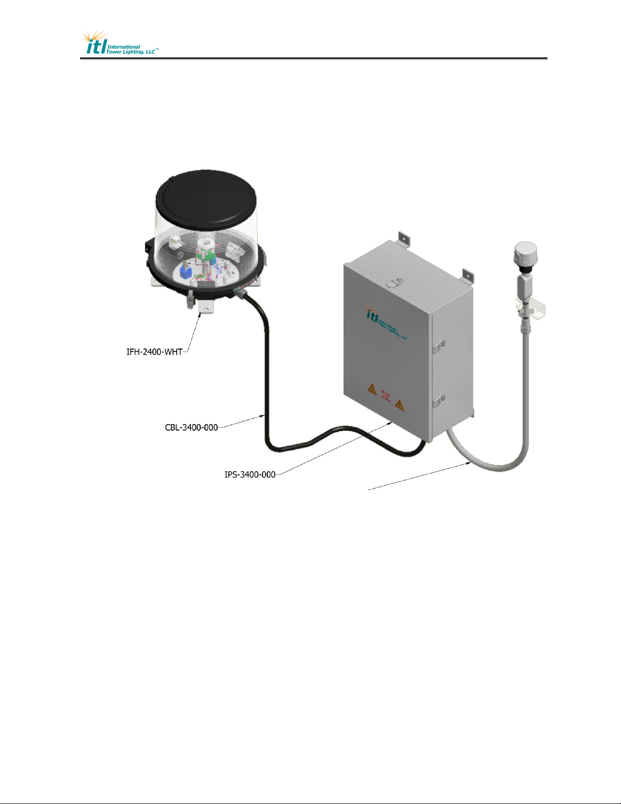
Figure 3: ILS-3400 Dual Strobe System .......................................................................... 11
Figure 4: IFH-1400-RED Red Flash Head ....................................................................... 13
Figure 5: IFH-2400 White Flash Head ............................................................................. 13
Figure 6: IFH-3400-000 Dual Red/White Flash Head ...................................................... 13
Figure 7: FH0-3400-000 Flash Tube Detail ..................................................................... 14
Figure 8: Flash Head Leveling - Axis 1 ............................................................................ 18
Figure 9: Flash Head Leveling - Axis 2 ............................................................................ 19
Figure 10: IFH-1400 / IFH-2400 Flash Head Dimensions and Mounting Detail ............... 20
Figure 11: IFH-1400 / IFH-2400 Flash Head Component Layout, Top View ................... 21
Figure 12: IFH-1400 / IFH-2400 Flash Head Component Layout, Isometric View ........... 21
Figure 13: IFH-1400 / IFH-2400 Flash Head Parts List Table ......................................... 22
Figure 14: IFH-1400 Red Flash Head Wiring Diagram .................................................... 23
Figure 15: Red Flash Head Component Locator Diagram ............................................... 23
Figure 16: IFH-2400 White Flash Head Wiring Diagram ................................................ 24
Figure 17: White Flash Head Component Locator Diagram ............................................ 24
Figure 18: IFH-3400 Dual Flash Head Dimensions and Mounting Detail - 1 ................... 25
Figure 19: IFH-3400 Dual Flash Head Dimensions and Mounting Detail - 2 ................... 26
Figure 20: IFH-3400 Dual Flash Head Component Layout, Top View ............................. 27
Figure 21: IFH-3400 Dual Flash Head Component Layout, Isometric View .................... 28
Figure 22: IFH-3400 Dual Flash Head Parts List Table ................................................... 29
Figure 23: IFH-3400 Dual Flash Head Wiring Diagram ................................................... 30
Figure 24: IFH-3400 Dual Flash Head Component Locator Diagram .............................. 31
Figure 25: IPS-3400 Power Supply Dimensions and Mounting Details ........................... 33
Figure 26: IPS-3400 Power Supply Overall Component Layout ...................................... 34
Figure 27: IPS-3400 Power Supply Parts List Table ........................................................ 35
Figure 28: IPS-3400 Power Supply Panel Component Locator ....................................... 36
Figure 29: IPS-3400 Power Supply Wiring Diagram ........................................................ 37
Figure 30: IPS-3400-30FPM Power Supply Wiring Diagram with Flashing Side Lights ... 38
Figure 31: IPS-3400 120VAC Primary ............................................................................ 39
Figure 32: IPS-3400 230/240VAC Primary ..................................................................... 39
Figure 33: IPS-3400 Configuration Quick Info Guide ....................................................... 40
Figure 33: PEC Assembly Drawing ................................................................................. 41
Figure 34: PEC Wiring Diagram ...................................................................................... 41
Figure 36: PEC Assembly Parts List Table ...................................................................... 42
Figure 37: ILS-1400 / ILS-2400 / ILS-3400 Installation Wiring Diagram .......................... 43
Figure 38: ILS-1400 / ILS-2400 / ILS-3400 Triple System Installation w/Sync and Data
Link ........................................................................................................................... 44
Figure 39: ILS-1400 Single System Typical Installation Diagram – 350’ ......................... 45
Figure 40: ILS-1400 Triple System Typical Installation Diagram – 500’ .......................... 46

ILS Strobe Lighting Systems
DOC-3400-MNL Rev23.doc (9/22/2021) Copyright 2007-2021 ITL, LLC Page 7 of 86
Figure 41: ILS-2400 Single System Typical Installation Diagram – 350’ ......................... 47
Figure 42: ILS-2400 Triple System Typical Installation Diagram – 500’ .......................... 48
Figure 43: ILS-3400 Single System Typical Installation Diagram – 350’ ......................... 49
Figure 44: ILS-3400 Triple System Typical Installation Diagram – 500’ .......................... 50
Figure 45: ITL-3400 Main Board Picture .......................................................................... 51
Figure 46: ITL-3400 LEDs Location Detail ....................................................................... 52
Figure 47: ITL-3400 LEDs Table ..................................................................................... 52
Figure 48: ITL-3400 Neon Trigger Indicator Location Detail ............................................ 53
Figure 49: ITL-3400 Toggle Switches Location Detail ..................................................... 54
Figure 50: ITL-3400 DIP Switch Location Detail .............................................................. 55
Figure 51: ITL-3400 Configuration DIP Switch SW4 Table .............................................. 55
Figure 52: ITL-3400 Configuration DIP Switch SW5 Table .............................................. 55
Figure 53: Strobe Configuration Detail Table .................................................................. 56
Figure 54: Sidelight Configuration Detail Table ............................................................... 56
Figure 55: ITL-3400 Factory Reset Switch Location Detail .............................................. 56
Figure 56: ITL-3400 SYNC Connector Location Detail 1 ................................................. 58
Figure 57: ITL-3400 Connector Location Detail 2 ............................................................ 58
Figure 58: ITL-3401-RLY Alarm Relay Board Picture ...................................................... 59
Figure 59: ITL-3420-SEN Sense Board Picture ............................................................... 60
Figure 60: ITL-3421-SEN Sense Board Picture ............................................................... 60
Figure 61: ITL-3410-0HV High Voltage Board Picture ..................................................... 61
Figure 62: ITL-3451-RNC R/C Board Picture .................................................................. 62
Figure 63: Strobe Light Simplified Diagram ..................................................................... 65
Figure 64: ILS-3800 Strobe/LED System ........................................................................ 76
Figure 65: ILS-3800 Installation Wiring Diagram ............................................................. 77
Figure 66: IPS-3800 Power Supply Panel Component Locator ....................................... 78
Figure 67: IPS-3800 Power Supply Wiring Diagram ........................................................ 79
Figure 68: IPS-3800 Configuration Quick Info Guide ....................................................... 80
Figure 69: IPS-3800 Power Supply Parts List Table ........................................................ 81
Figure 70: IPS-3800 Single Typical Installation Diagram – 350’ ...................................... 82

ILS Strobe Lighting Systems
DOC-3400-MNL Rev23.doc (9/22/2021) Copyright 2007-2021 ITL, LLC Page 8 of 86
Introduction
Congratulations, and thank you for choosing an ITL PULSAR XENON Series lighting
system.
We trust that ITL’s reputation for technical excellence, experience in product
development, commitment to our customers and testing will ensure your complete
satisfaction.
You have chosen one of the most technologically innovative strobe lighting systems
available on the market today. This product is the result of many years of engineering
with extensive input from field service personnel.
This manual covers the
ILS-1400 FAA type L-864 red strobe lighting system with side lights
FAA Type L-810
ILS-2400 FAA type L-865 white strobe lighting system
ILS-3400 FAA type L-864/5 dual strobe lighting system with side lights
FAA type L-810
ILS-3800 FAA type L-864(L)/L-865 white strobe / red LED system with side lights
FAA type L-810 or L-810(L), see Appendix A
Please take the time to read and familiarize yourself with this manual. It contains the
information necessary to install, test and troubleshoot the ILS strobe lighting systems.

ILS Strobe Lighting Systems
DOC-3400-MNL Rev23.doc (9/22/2021) Copyright 2007-2021 ITL, LLC Page 9 of 86
Product Description
The ILS-1400 FAA type L-864, ILS-2400 FAA type L-865 and ILS-3400 FAA type L-
864/L-865) are medium intensity strobe lighting systems as defined by the FAA’s advisory
circular, AC150-5345-43F. Both lighting systems meet or exceed the specifications as
defined in the advisory circular. For more information on those specifications please refer
directly to the FAA website www.faa.gov/airports_airtraffic/airports.
Each system consists of a power conversion unit, the IPS-3400, a strobe cable, and a
single red (IFH-1400) or white (IFH-2400) or dual white/red (IFH-3400) flash head.
The ILS-1400 is a red only system which produces a low intensity red “burst” of rapid
flashes every 3 seconds (20 FPM) in Night Mode. See major component block diagram
below.
Figure 1: ILS-1400 Red Strobe System

ILS Strobe Lighting Systems
DOC-3400-MNL Rev23.doc (9/22/2021) Copyright 2007-2021 ITL, LLC Page 10 of 86
The ILS-2400 is a white only system which produces 1 medium intensity white flash every
1.5 seconds equating to 40 flashes per minute (FPM) in Day Mode and a low intensity
white “burst” of rapid flashes every 1.5 seconds (40 FPM) in Night Mode. See major
component block diagram below.
Figure 2: ILS-2400 White Strobe System

ILS Strobe Lighting Systems
DOC-3400-MNL Rev23.doc (9/22/2021) Copyright 2007-2021 ITL, LLC Page 11 of 86
By contrast, the ILS-3400 is a dual white/red system which produces 1 medium intensity
white flash every 1.5 seconds (40 FPM) in Day Mode to the lower of the two tubes and a
low intensity red “burst” of rapid flashes every 3 seconds (20 FPM) in Night Mode to the
upper of the two tubes. See major component block diagram below.
The intensity for all lighting systems is 20,000cd for a day flash and 2,000cd for a burst of
night flashes.
Figure 3: ILS-3400 Dual Strobe System

ILS Strobe Lighting Systems
DOC-3400-MNL Rev23.doc (9/22/2021) Copyright 2007-2021 ITL, LLC Page 12 of 86
Power Conversion, IPS-3400
Both systems utilize the same power conversion unit, the IPS-3400 power supply. This
power supply stores high voltage energy in capacitors which are discharged into the flash
head’s Xenon gas discharge tube(s) (flash tube) in order to produce short brilliant flashes.
The power supply contains a step-up transformer and voltage rectifier board (ITL-3410-
0HV) which converts the incoming 115/230VAC and stores it in the unit’s capacitors. In
particular the unit has a bank of capacitors which are used to store the energy for a day
flash and a single capacitor which stores the energy used for the night burst.
A microprocessor controlled circuit board, the ITL-3400, is the brain of the power supply.
It times the exact triggering of the flash tube(s), controls the intensity of the flashes and
handles any alarming in case of component failure. This circuit board takes input from an
electric photocell (PEC) in order to switch the unit from Day to Night flashing based on the
ambient light. Subsequently the circuit board controls off-board relays in order to change
the intensity (energy) applied to the flash tube(s). For daytime operation the circuit board
will generate a trigger to the day flash tube every 1.5s. For nighttime operation the circuit
board will generate a trigger to the flash tube every 1.5s for white night operation or every
3s for red night operation.
After each flash the ITL-3400 then examines the intensity of the flash and either confirms
the successful flashing or generates an alarm otherwise.
Several smaller circuit boards are connected to the ITL-3400 main board. The ITL-3420-
SEN senses the strobe and sidelight energy while the ITL-3401-RLY contains several
dry-contact Form-C alarm relays. For further details about any of these boards please
refer to sections below or consult the table of contents or index.
The main board also conveniently connects to one of several ITL communication boards.
These boards however are separate products and are not part of any standard IPS-3400
configuration. In particular, the ITL-3430-PCS provides CDMA or GPRS wireless
communication, the ITL-3431-SAT communicates via satellite, while the ITL-3432-POT
provides a traditional dial-up connection.

ILS Strobe Lighting Systems
DOC-3400-MNL Rev23.doc (9/22/2021) Copyright 2007-2021 ITL, LLC Page 13 of 86
Flash head, IFH-1400/2400/3400
There are three omni-directional flash head configurations available to connect to the
IPS-3400. The IFH-1400 (L-864) is a single acrylic red lens flash head with one flash
tube. Its configuration provides for red-only operation. The IFH-2400 (L-865) is a single
acrylic clear lens flash head with one flash tube. Its configuration provides for white-only
operation, i.e. white strobe at daytime and white strobe at nighttime.
The IFH-3400 by contrast contains two acrylic lenses and two flash tubes and in essence
stacks two flash heads on top of each other. The upper red lens is used for nighttime red
strobe operation while the lower clear lens is used for daytime white strobe operation, and
white backup operating, in case of red failure.
Figure 4: IFH-1400-RED Red Flash Head Figure 5: IFH-2400 White Flash Head
Figure 6: IFH-3400-000 Dual Red/White Flash Head

ILS Strobe Lighting Systems
DOC-3400-MNL Rev23.doc (9/22/2021) Copyright 2007-2021 ITL, LLC Page 14 of 86
Besides the flash tube, each flash head contains terminals to connect the flash head
cable from the power supply, a coupling transformer, a trigger transformer, a R/C network,
and an interlock switch. The transformers shape the amplitude of the trigger pulse
applied to the flash tube. The interlock switch is provided for safety and disconnects the
high voltage from the flash tube and also stops triggering the tube.
The flash tubes are three terminal Xenon-filled glass discharge tubes. High voltage is
applied across two of the terminals of the flash tube, the positive electrode or anode and
the negative electrode or cathode. A third terminal, the trigger, is used to temporarily
energize the tube and produce a short brilliant white flash.
Figure 7: FH0-3400-000 Flash Tube Detail

ILS Strobe Lighting Systems
DOC-3400-MNL Rev23.doc (9/22/2021) Copyright 2007-2021 ITL, LLC Page 15 of 86
Specifications
Complies with AC150/5345-43G
Environment
Temperature -40°C to +55°C
Humidity less than 95% relative humidity (non-
condensing)
Light Output
Day Intensity 20,000 +/-25% effective candelas
Night Intensity 2,000 +/-25% effective candelas
Beam Pattern 360º horizontal, ≥3º vertical
Day Flash Rate 40 FPM
White Night Flash Rate 40 FPM
Red Night Flash Rate 20 FPM
Side Lights 0 to 4 L-810 type incandescent. Or
L-810(L) LED (steady burning or flashing)
Mechanical
IFH-1400/2400
Dimension Height: 15” (38.1cm)
Diameter: 16.5” (42cm)
Weight 13 lbs (6Kg) max
IFH-1700 (LED) (ILS-3800 only)
Dimension Height: 11” (27.7cm)
Diameter: 16.5” (42cm)
Weight 28 lbs (13Kg) max
IFH-3400 Flash Head
Dimension Height: 25” (63.5cm)
Diameter: 16.5” (42cm)
Weight 24 lbs (11Kg) max
IPS-3400/3800 Power Supply
Dimension Height: 23.63” (60.02cm)
Width: 16.57” (42cm)
Depth: 9.76” (24.8cm)
Weight 65 lbs (30Kg) max

ILS Strobe Lighting Systems
DOC-3400-MNL Rev23.doc (9/22/2021) Copyright 2007-2021 ITL, LLC Page 16 of 86
Electrical
IPS-3400
Input Power 120/240VAC at 60Hz
Power Consumption Day: 180W
Red Night: 140W
White Night: 65W
IPS-3800 (ILS-3800 only)
Input Power 120/240VAC at 60Hz
Power Consumption Day: 180W
Red Night: 48W
White Night: 65W

ILS Strobe Lighting Systems
DOC-3400-MNL Rev23.doc (9/22/2021) Copyright 2007-2021 ITL, LLC Page 17 of 86
Installation
The following section describes how to install the strobe lighting system. Based on the
type of system you are going to install please refer to the appropriate wiring diagram in
section ILS-1400 / ILS-2400 / ILS-3400/ ILS-3800 Installation Wiring Diagram.
Unpacking your Strobe Lighting System
Please examine the shipping containers and their content thoroughly upon receipt and
report any potential shipping damage to the carrier.
Tools for Installation
The following tools are suggested for mounting of the ITL power supply and flash head.
Digital multi-meter capable of reading 600VAC/DC (Fluke 177 or 179)
Nut Drivers and Sockets
#2 Phillips Screwdriver
5/16 Flat Head screwdriver
Crimp Tool
Needle Nose Pliers
Quick Installation Guide
The quick start guide shows how to install the ILS strobe lighting systems. The guide
provides only basic instructions for more details, refer to this document.
Remove packaging material from inside power supply and flash head
Mount the power supply cabinet.
Ground the power supply cabinet to the site grounding system using an AWG6
copper conductor.
Using the mounting holes provided in the bottom of the cabinet ground the power
supply cabinet to the site grounding system using an AWG 6 copper conductor and
a two-hole (5/8” centers) compression lug.
Mount the flash head using the hardware supplied.
Install sidelights (ILS-1400, ILS-3400 & ILS-3800 only)
Connect strobe cable to both, power supply and flash head
Connect PEC
Install strobe tube(s) into flash head
Attach primary power cable
Apply power to unit (pull interlock switch)
Observe red alarm LEDs off
Observe yellow confirm LED blinks every 1.5s in day mode and every 1.5s in night
mode for the ILS-2400 or every 3s in night mode for the ILS-3400 system

ILS Strobe Lighting Systems
DOC-3400-MNL Rev23.doc (9/22/2021) Copyright 2007-2021 ITL, LLC Page 18 of 86
Cover PEC and observe Day to Night switching
Toggle manual mode switch from Day to Night and observe that unit’s operation
follows switch (PEC Alarm LED will be lit when switch is not in auto mode)
Move manual toggle switch back to ‘Auto’ position
Generate strobe and sidelight failure and observe subsequent alarming
All fixtures, enclosures and junction boxes must be mounted in the upright position.
Flash Head
Flash heads need to be mounted such that all four mounting feet are in direct contact with
an unpainted surface in order to allow for proper grounding of the electrical components.
It also needs to be mounted such that it will not obstruct access to the internal
components for the purpose of installing and maintaining the equipment. The following
diagrams detail the mounting dimensions and clearance for proper access.
Leveling
Flash heads need to be leveled properly for correct vertical beam spread. The following
diagrams detail how to use a compact “torpedo” level on two axes to ensure that the flash
head is mounted level. If the flash head mounting surface is not level already use shims
to correct. Do not compromise grounding of the four flash head mounting feet.
Figure 8: Flash Head Leveling - Axis 1

ILS Strobe Lighting Systems
DOC-3400-MNL Rev23.doc (9/22/2021) Copyright 2007-2021 ITL, LLC Page 19 of 86
Figure 9: Flash Head Leveling - Axis 2

ILS Strobe Lighting Systems
DOC-3400-MNL Rev23.doc (9/22/2021) Copyright 2007-2021 ITL, LLC Page 20 of 86
IFH-1400/2400 Flash Head Mounting
Figure 10: IFH-1400 / IFH-2400 Flash Head Dimensions and Mounting Detail
4 SETS OF MOUNTING HARDWARE
BOLT HDW-B500-150-GAL
LOCK WASHER HDW-0500-LGA
H.H.NUT HDW-0500-NGA
INCLUDED
This manual suits for next models
3
Table of contents
Other ITL Lighting Equipment manuals