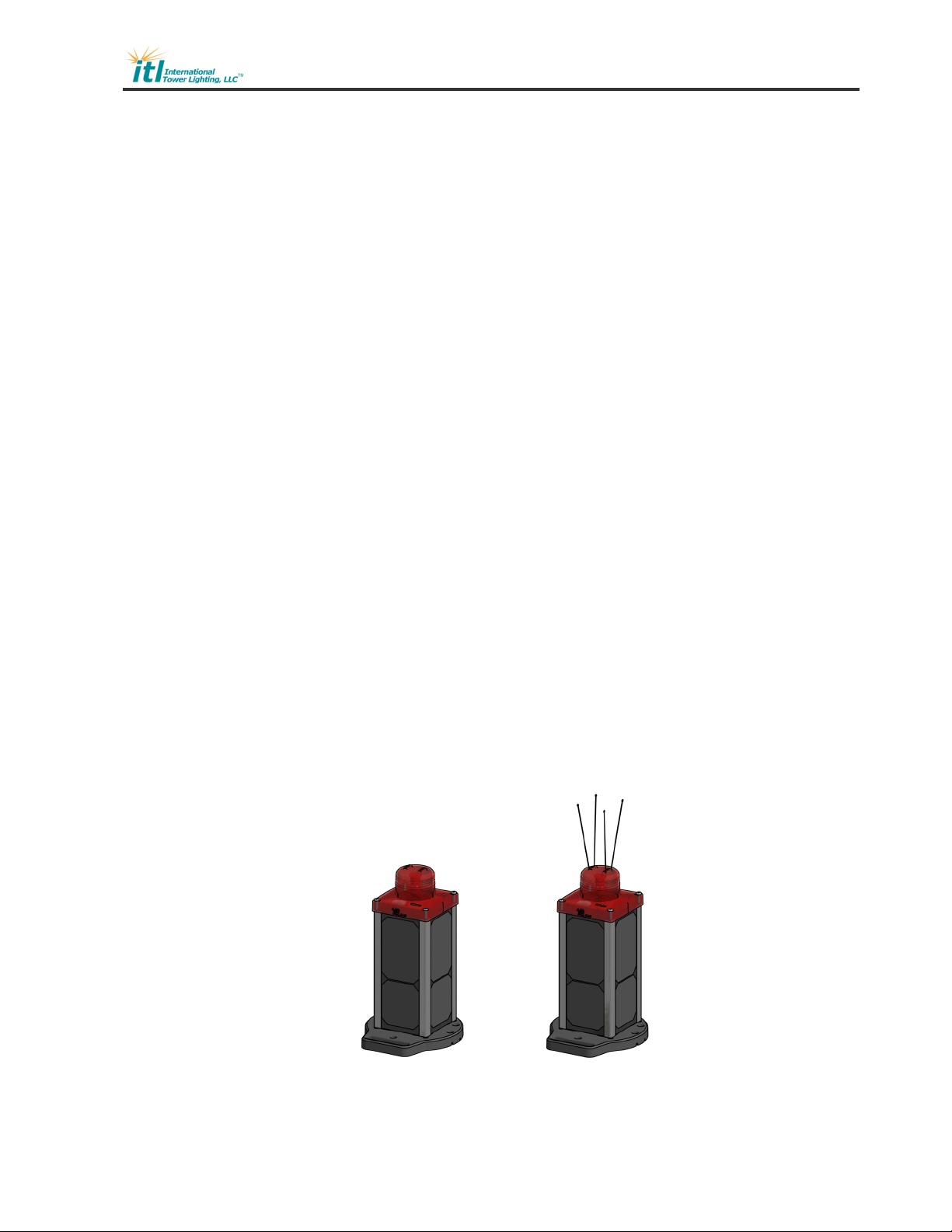
ITL SOLARIS ILS-S810-0IR Service manual

Toll Free: +1 (866) 624-8309 www.itl-llc.com
Installation
Instruction Manual
ILS-S810-0IR
L-810(L) Solar
Red LED with Infrared
(IR) Obstruction Light
SOLARIS

ILS-S810-0IR
DOC-S810-0IR-MNL Rev1.doc (9/22/2021) Page 2 of 18
Copyright 2021 ITL, LLC
Front Matter
Copyright & Trademarks
Copyright © 2021 by ITL, LLC. All rights reserved. This document contains proprietary
information, photographs, graphics, and other material (collectively, "the Content")
protected by copyright, and this manual and all accompanying hardware, software and
documentation are copyrighted. No part of this document may be photocopied or
reproduced by mechanical, electronic, or other means in any form without written consent
of ITL, LLC.
ITL, LLC, ILS-S810-0IR and the ITL logo are trademarks of ITL, LLC. All other
trademarks and brand names are the property of their respective proprietors.
Limited Warranty and Disclaimer
ITL, LLC guarantees that ILS-S810-0IR obstruction lights are free from physical defects of
material and workmanship under normal use for two (2) year from the date of purchase.
If the product proves defective during this warranty period, please contact ITL, LLC in
order to obtain a Return Authorization Number, RMA.
In no event shall ITL, LLC’s liability exceed the price paid for the product from direct,
indirect, special, incidental, or consequential damages resulting from the use of the
product, its accompanying software, or its documentation. ITL, LLC makes no warranty
or representation, expressed, implied, or statutory, with respect to its products or the
contents or use of this documentation and all accompanying software, and specifically
disclaims its quality, performance, merchantability, or fitness for any particular purpose
unless otherwise stated.
The technical documentation is being delivered to you AS-IS. ITL, LLC makes no
warranty as to its accuracy or use. Any use of the technical documentation or the
information contained therein is at the risk of the user. Documentation may include
technical or other inaccuracies or typographical errors. ITL, LLC reserves the right to
revise or update its products, software, or documentation without obligation to notify any
individual or entity.
Please send any comments regarding the manual to [email protected].

ILS-S810-0IR
DOC-S810-0IR-MNL Rev1.doc (9/22/2021) Page 3 of 18
Copyright 2021 ITL, LLC
Table of Contents
Front Matter ....................................................................................................................... 2
Copyright & Trademarks ................................................................................................ 2
Limited Warranty and Disclaimer ................................................................................... 2
List of Illustrations and Tables ........................................................................................... 4
Introduction ........................................................................................................................ 5
Product Description ........................................................................................................... 5
Specifications .................................................................................................................... 6
Installation ......................................................................................................................... 7
Unpacking your LED Obstruction Light .......................................................................... 7
Tools for Installation ....................................................................................................... 7
Quick Installation ............................................................................................................ 7
Infrared Remote Control ................................................................................................ 8
Leveling ......................................................................................................................... 9
Mounting Detail ............................................................................................................ 10
Bird Deterrent Installation ............................................................................................ 11
Spare Parts ..................................................................................................................... 12
Maintenance .................................................................................................................... 13
Battery Replacement ....................................................................................................... 14
Battery Charging.............................................................................................................. 15
Long Term Storage .......................................................................................................... 15
Lens Replacement ........................................................................................................... 16
Technical Support and Contact Information .................................................................... 17
Contact Information ...................................................................................................... 17
RMA ............................................................................................................................. 17
Appendix A – Troubleshooting ..................................................................................... 18

ILS-S810-0IR
DOC-S810-0IR-MNL Rev1.doc (9/22/2021) Page 4 of 18
Copyright 2021 ITL, LLC
List of Illustrations and Tables
Figure 1: ILS-S810 Solar Red LED with Infrared Obstruction Light ................................... 5
Figure 2: Infrared Remote Control Port ............................................................................. 8
Figure 3: Leveling .............................................................................................................. 9
Figure 4: Outline Dimension sand Mounting Detail .......................................................... 10
Figure 5: Spare Part Locations ........................................................................................ 12
Figure 6: Battery Assembly ............................................................................................. 14
Figure 7: Battery Charging .............................................................................................. 15
Figure 8: Lens Assembly ................................................................................................. 16

ILS-S810-0IR
DOC-S810-0IR-MNL Rev1.doc (9/22/2021) Page 5 of 18
Copyright 2021 ITL, LLC
Introduction
Congratulations, and thank you for choosing an SOLARIS Red LED with Infrared (IR)
obstruction light.
We trust that ITL’s reputation for technical excellence, experience in product
development, commitment to our customers and testing will ensure your complete
satisfaction.
You have chosen one of the most technologically innovative LED obstruction lights
available on the market today. This product is the result of many years of engineering
with extensive input from field service personnel.
This manual covers the ILS-S810-0IR Solar Red LED with Infrared (IR) Obstruction Light.
Please take the time to read and familiarize yourself with this manual. It contains the
information necessary to install, test and troubleshoot the ILS-S810-0IR Obstruction
Light.
Product Description
The ILS-S810-0IR Solar Red LED with Infrared (IR) obstruction light utilizes LED
technology and Fresnel Optics to provide a reliable solar power lighting solution.
The ITL, LLC L-810(L) Solar Red LED with Infrared (IR) obstruction light complies with
applicable FAA specifications for marking hazards to air navigation such as towers,
smoke stacks or similar structures. It is intended for installations which require FAA L-
810(L) red lights.
Figure 1: ILS-S810 Solar Red LED with Infrared Obstruction Light

ILS-S810-0IR
DOC-S810-0IR-MNL Rev1.doc (9/22/2021) Page 6 of 18
Copyright 2021 ITL, LLC
Specifications
Complies with FAA AC150/5345-43H or AC150/5345-43J (selectable), Type L-810 (L)
Complies with FAA Engineering Brief 67 and Engineering Brief 98
Intensity: 32.5 effective candelas (min.), Red
4mW/sr (min.), 800-900nm, Infrared
Beam: 360° Horizontal,
10° Vertical (min.)
Height: 16.8 Inches (42.7 cm)
(bird deterrent not included)
Width: 10.5 Inches (26.7 cm)
Weight: 14.0 lbs. (6.4 Kg)
Voltage: Battery: 6 - 12 VDC
Input: 7 - 12 VDC (1 A max)
Temperature: -40°C to +55°C
Humidity: less than 95%, non-condensing

ILS-S810-0IR
DOC-S810-0IR-MNL Rev1.doc (9/22/2021) Page 7 of 18
Copyright 2021 ITL, LLC
Installation
The following section describes how to install the ILS-S810-0IR obstruction light.
Unpacking your LED Obstruction Light
Please examine the shipping containers and their content thoroughly upon receipt and
report any potential shipping damage to the carrier.
Tools for Installation
The following tools are suggested for mounting of the ILS-S810 obstruction lights.
Digital multi-meter capable of reading 600VAC/DC (Fluke 177 or 179)
Nut Drivers and Sockets
#2 Phillips Screwdriver
Infrared Remote Control (Optional)
Quick Installation
The ILS-S810-0IR requires direct sunlight exposure for up to 40 minutes to activate after
being removed from the packaging. The unit will indicate it is functioning by flashing red
LED I3 every 5 seconds. See next section for selection of 43H or 43J Red Intensity.
The ILS-S810-0IR includes standard industry 3 and 4 hole mounting patterns.
The ILS-S810-0IR must be mounted in the upright position.
Use the mounting kit to attach the base. Do not mount in an area that is often shaded.
Visually verify proper day/night operation.

ILS-S810-0IR
DOC-S810-0IR-MNL Rev1.doc (9/22/2021) Page 8 of 18
Copyright 2021 ITL, LLC
Infrared Remote Control
An optional infrared remote control (P/N ILS-S810-IRC) is available to communicate with
the ILS-S810. For best results the Infrared Remote Control should be pointed at the IR
Port at the front of the ILS-S810 as shown in the figure below. LED1 on the ILS-S810 will
blink after each button press received from the remote control. LED1 will blink twice to
confirm a command has been received.
The ILS-S810-0IR comes from the factory with Flashing disabled. Flashing must remain
disabled (factory default) for compliance with FAA Advisory Circulars.
The ILS-S810-0IR comes from the factory set for FAA AC 150/5345-43H Red Intensity. If
150/5345-43J compliance is required this can be selected using the infrared remote
control (see table below). Note that 43J Red Intensity requires higher power consumption
and will affect battery performance. See your FAA issued Determination of No Hazzard
to determine which intensity is required.
Function Code* Description
Battery Level 228<Enter>
3 LEDs on = Fully Charged
2 LEDs on = Good
1 LED on = Okay
1 LED Blinking = Low
Enable Flashing 352<Chan Up> Enables flashing operation (30FPM)
Disable Flashing 352<Chan Down> Disables flashing operation (steady burning
operation selected, factory default)
Enable 43H Red
Intensity
434<Chan Up> Enables FAA 154/5340-43H Red Intensity
(factory default)
Disable 43H Red
Intensity
434<Chan Down> Disables FAA 154/5340-43H Red Intensity,
(Higher power consumption 43J Intensity
Enabled)
Power Off 769<Power> Places the ILS-S810 in a low power state for
storage. Expose to direct sun light to turn
on.
*The numeric codes represent the letters of a telephone keypad. For example the code for Battery Level, 228, is B-A-T on a
telephone keypad. The Channel Up button is used for turning On a function and the Channel Down for turning Off a function.
Figure 2: Infrared Remote Control Port

ILS-S810-0IR
DOC-S810-0IR-MNL Rev1.doc (9/22/2021) Page 9 of 18
Copyright 2021 ITL, LLC
Leveling
TheILS-S810-0IR must be leveled during installation for correct vertical bean alignment.
The following diagrams detail how to use a compact “torpedo” level on two axes to ensure
that the obstruction light is level mounted level. Place the level across the base as shown
and repeat on an adjacent side to level both axis.
Figure 3: Leveling

ILS-S810-0IR
DOC-S810-0IR-MNL Rev1.doc (9/22/2021) Page 10 of 18
Copyright 2021 ITL, LLC
Mounting Detail
Figure 4: Outline Dimension sand Mounting Detail

ILS-S810-0IR
DOC-S810-0IR-MNL Rev1.doc (9/22/2021) Page 11 of 18
Copyright 2021 ITL, LLC
Bird Deterrent Installation
1. Align bird deterrent wires with snap-in slots
2. Snap bird deterrent wires into slots
3. Complete remaining bird deterrent wire installation

ILS-S810-0IR
DOC-S810-0IR-MNL Rev1.doc (9/22/2021) Page 12 of 18
Copyright 2021 ITL, LLC
Spare Parts
ILS-S810-0IR Spare Parts
ITL Order P/N Description
ILS-S810-0IR-TAS Combination Lens and Lamp
LEN-S180-0IR S810-0IR Lens
ITL-S814-BAT S810 Battery Pack
ILS-S810-CHG Battery Charger (not shown)
HAR-S810-PWR Battery Connector Wiring Harness
ILS-S810-IRC Infrared Remote Control (not shown)
ILS-S810-BRD Bird Deterrent (not shown)
Figure 5: Spare Part Locations

ILS-S810-0IR
DOC-S810-0IR-MNL Rev1.doc (9/22/2021) Page 13 of 18
Copyright 2021 ITL, LLC
Maintenance
The maintenance outlined below should be performed at least once annually.
Verify that the fixture is functional in all operating modes with no indication of an
alarm condition on alarm indicator lights, alarm dry contacts, or digital monitoring
interfaces.
Verify that the photoelectric control operates the system in the correction operating
mode (day/night) when exposed to light and dark ambient lighting conditions.
Inspect the fixture for any type of obstruction that could block light output at any
point along the 360 degree horizontal output of the fixture. Note that multiple
fixtures may be used to achieve 360 degree coverage.
Inspect lenses and transparent covers for damage.
Clean the fixture lens or transparent cover using a mild detergent and soft
nonabrasive cloth.
Check the battery voltage by removing the lens and then testing the terminals of
the battery connector with a multimeter.
Ensure that no water is present inside the housing.

ILS-S810-0IR
DOC-S810-0IR-MNL Rev1.doc (9/22/2021) Page 14 of 18
Copyright 2021 ITL, LLC
Battery Replacement
The battery can be accessed by the removing the bottom of the ILS-S810. Note that the
ILS-S810-0IR will automatically begin flashing operation under extreme low battery
conditions.
1. Remove the base screws from the base (HDW-2520-62S).
2. Slide the base out of the fixture
3. Disconnect the battery cable from the battery (HAR-S810-PWR).
4. Remove the battery screws securing the battery to the base (HDW-2510-075S).
5. Slide the battery out of the base.
6. Slide replacement battery into base.
7. Reconnect battery cable.
8. Secure the battery with battery screws and rubber washers.
9. Ensure the gasket is flush in the gasket channel (ILS-S810-GSL).
10. Slide the battery and base back into the fixture and replace the base screws
(see figure 6 for more details).
Figure 6: Battery Assembly

ILS-S810-0IR
DOC-S810-0IR-MNL Rev1.doc (9/22/2021) Page 15 of 18
Copyright 2021 ITL, LLC
Battery Charging
An optional battery charger (P/N ILS-S810-CHG) is available for charging the batteries
from a standard 120Vac wall outlet. Note that the ILS-S810-0IR will automatically begin
flashing operation under extreme low battery conditions.
1. Remove the lens screws from the lens and fixture body (HDW-2520-125S)
(not shown for clarity).
2. Disconnect the 4-position Solar Panel Cable.
3. Connect the charger cable in place of the solar panel cable on the ILS-S810.
4. Plug the battery charger into a standard 120Vac wall outlet and allow time for the
batteries to charge. Charging may take several hours. Charging will automatically
stop when the batteries are fully charged.
5. Check the battery level using the Infrared Remote Control (see page 8).
6. When the batteries are fully charged unplug the charger from the wall outlet and
disconnect from the ILS-S810.
7. Reconnect Solar Panel Cable in the ILS-S810.
8. Replace the lens on the body and secure with lens screws.
(see figure 7 for more details).
Long Term Storage
1. Remove the lens screws from the lens and fixture body (HDW-2520-125S).
2. Disconnect the Battery Cable by unplugging the 5-position green connector.
Figure 7: Battery Charging

ILS-S810-0IR
DOC-S810-0IR-MNL Rev1.doc (9/22/2021) Page 16 of 18
Copyright 2021 ITL, LLC
Lens Replacement
1. Remove the lens screws from the lens and fixture body (HDW-2520-125S).
2. Disconnect the battery cable and solar panel cable.
3. Remove the PCB screws (HDW-0424-31S-TR).
4. Place PCB in new lens ensuring that the PCB orientation hole is aligned with the
lens orientation indicator stud.
5. Replace PCB screws.
6. Reconnect the battery cable and solar panel cable.
7. Replace lens on body and secure with lens screws.
(see figure 8 for more details).
Figure 8: Lens Assembly

ILS-S810-0IR
DOC-S810-0IR-MNL Rev1.doc (9/22/2021) Page 17 of 18
Copyright 2021 ITL, LLC
Technical Support and Contact Information
Contact Information
For information on the ILS-S810-0IR Solar Red LED with Infrared (IR) obstruction lights’
basic functions, refer to this manual and the accompanying drawings. For additional help
with the installation or operation of any ITL products, please contact ITL, LLC at one of
the following below.
Web and Internet Sites
Corporate home page: http://www.itl-llc.com
Customer Support Technicians
(8:00 AM - 5:00 PM Central Time)
US and Canada call: +1-615-256-6030
Toll Free: +1-866-624-8309
RMA
Please contact ITL, LLC before returning equipment for repair and obtain a Return
Material Authorization (RMA) number.

ILS-S810-0IR
DOC-S810-0IR-MNL Rev1.doc (9/22/2021) Page 18 of 18
Copyright 2021 ITL, LLC
Appendix A – Troubleshooting
1. If the ILS-S810 will not turn on at night:
a. Ensure the light is located in a dark environment (below 30 foot candles).
b. Ensure that the unit has been exposed to direct sunlight for at least 30
minutes to activate by checking that LED I3 is blinking every 5 seconds.
c. Ensure that the battery is above the shutdown voltage.
2. If the ILS-S810 will not turn off during the day:
a. Ensure that the solar panel cable is connected inside the ILS-S810.
3. If the ILS-S810 does not respond to the Infrared Remote Control:
a. Ensure that the ILS-S810 is on by exposing it to direct sunlight for up to 40
minutes. LED I3 will blink once every 5 seconds when the unit is on.
b. Replace the battery in the Infrared Remote Control.
4. If the ILS-S810 begins flashing at night when flashing is disabled this indicates an
extremely low battery condition.
a. See section Battery Replacement.
Revision Description of Change Date Preparer / Approval
0 Initial Release 3/3/2021 Prepared By: Elke Hinson
Approved By: Andy Rudolph
1 Updated Title, added “SOLARIS”. 9/22/2021 Prepared By: Elke Hinson
Approved By: Andy Rudolph
Table of contents
Other ITL Lighting Equipment manuals
Popular Lighting Equipment manuals by other brands

Banner
Banner EZ-STATUS WLS27 Series instruction manual

Unex
Unex RISP 43 W operating manual

Armacost Lighting
Armacost Lighting GroFlex GFS2835060 quick start guide

California Accent Lighting
California Accent Lighting lipLEDs LLED8600-RME installation instructions

Lightolier
Lightolier Baselyte-BSL12 datasheet

HC Stage Lighting
HC Stage Lighting HC-044 user manual