ITOH DENKI PM605KT Guide

POWER MOLLER
User Manual for the dedicated driver card can be downloaded from our website:
Home > Documents > Technical documentation
ITOH DENKI
ITOH DENKIITOH DENKI
POWER MOLLER
ITOH DENKIITOH DENKI
P
O
WE
WE
R
R
M
O
LL
L
ER
ER
R
PO
WE
WE
R
R
MO
LL
L
ER
ER
R
PM605KT/PM605KT-B
Motor Driven Roller
Thank you for purchasing ITOH DENKI products.
(hereinafter referred to as “This Product”)
*This Product does not include the dedicated driver card.
Read this manual before use
Brushless DC MDR for heavy duty pallet handling
〈Technicaldocumentation 〉
Read this manual carefully and familiarize yourself to the product
as well as the information on safety and precautions before using
and operating the product.
Keep this manual readily accessible for future reference.
Convey
Original notice - A1.1
https://www.itoh-denki.com/en/documents/technical-documentation/motorized-rollers

CBM-105
CBR-306
HBR-605
CBM-105
CBR-306
HBR-605
CBM-105
CBR-306
CBK-109
CB016B
HBM-201
IB-E
IB-P
&ඖගකඔඛ 0ගකඑජඍඌකඔඔඍකඛ 0ඌඝඔඍඛ
Standard circuit board
ZPA circuit board
HB510 HB510B
Corresponding circuit board Max load to be conveyed Mechanical brake version
Module circuit board
HBR-605
90° transfer
POP-UP
HBK-608
45° transfer
DC Brushless
Ø50
PM500 XE
Ø60,5
PM605 XE
B&W AS-i 3.0
Wenglor
B&W AS-i 3.0
Wenglor
PM500 XK
PM500 XC
PEPPERL-FUCHS
AS-Interface
B&W AS-i 3.0
PEPPERL-FUCHS
AS-Interface
B&W AS-i 3.0
Ø32
Ø50
Ø60,5
PM320 HS CB018
PM500 FE
CBM-105
HB510
IB-E
PM500 FE-B CB016B
HB510B
PM605 FE
PM605 FE-B CB016B
HB510B
CBM-105
HB510
IB-E
Network controller
IB-E
IB-P
PM500 VE
CBV-108
HBV-609
IB-P
PM605 VE
CBV-108
HBV-609
IB-P
PM500 XP B&W AS-i 3.0
Wenglor
PM605 XP B&W AS-i 3.0
Wenglor
B
B
Compatible module / sensor
CBR-306
CB018
CB016 CB016B
CBK-109BCBK-109
CBM-105
CBV-108
Replacing
CB030
HBM-201
solutions
F-RAT-S250
F-RAT-S300
F-RAT-NX75
External
circuit board
Integrated
circuit board
HBV-609
PM605 KT
CBK-109
HBK-608
IB-P
IB-E
PM605 KT-B CBK-109B
B
PM605KT/PM605KT-BTechnicaldocumentation
2
Productrange
Productrange
Original notice - A1.1

PM605KT/PM605KT-BTechnicaldocumentation
3
On the document, PM605KT/PM605KT-B series heavy duty pallet handling motorized roller
is referred to as MDR.
Model number PM605KT/PM605KT-B is also referred to in parallel from time to time.
About product
reference
・Allows heavy duty pallet handling with 60.5 diameter roller.
・Allows the creation of low profile conveyor.
・Available roller tube length minimum 340mm up to 1500mm maximum.
・Use of mechanical brake allows precise stop and holding the goods in position.
■Mechanical brake option is not recommended for decline conveyor application.
1.Introduction
Features
Disclaimer
This product is designed as a general industrial device. Do not use for other
applications. We do not take any responsibility for any damage that may result from
the disregarding of these warnings.
Also, in the event that an accident results from the use of this product, we do not
compensate for any damage, including abnormalities of equipment, connection
devices, and/or software, any damage resulting from malfunctions, and/or any other
secondary damage.
There are some examples of parts that need to be prepared by customers, as
explained within this manual. However, this does not provide any guarantee against
the existence of any rights, such as our industrial property rights, or those of other
companies, in advance.
Notes on industrial
property rights
We respond to technical inquiries based on the contents described within this manual,
and on this product within the range of general items for this product unit with
standard specifications, and for the options prepared by us.
There are some descriptions in this manual, about parts, equipment, and wiring
arranged by customers, as well as the controls and operation under such
circumstances. However, these are not included in the guaranteed operating range
and/or support.
When in use, please check and perform the aforementioned based on your
responsibility according to operation.
Notes on technical
support
Disclaimer
Original notice - A1.1

PM605KT/PM605KT-BTechnicaldocumentation
4
2. Procedures from installation to operation
Some errors have been found.
Prepare the 24V DC power supply, such as DC power supply units.
Prepare a PC / Install the application
Open the package, and check the model, specifications, voltage, etc.
Check accessories.
Advance preparation
Start using only after you have understood all the product’ s functions, safety
information, and precautions.
Read this manual
Product check
Perform maintenance and inspection
based on corresponding parts.
Maintenance
Switch settings.
Control
Commissioning before operation.
Commissioning
Run operation.
Install the MDR.
Installation
Mount driver cards.
Connect power and signal cables to driver cards.
Wiring
No
Yes
Procedures from
installation to operation
P.12 〜
P.17〜
P.20〜
Procedures from installation to operation
See Technical doc
for dedicated
driver.
See Technical doc
for dedicated
driver.
Original notice - A1.1

PM605KT/PM605KT-BTechnicaldocumentation
5
1.
2.
3.
4.
5.
6.
7.
Appendix
Introduction
Procedures from installation to operation
Safety precautions
3-1. General precautions
3-2. Precautions on installation
3-3. Precautions on wiring
3-4. Precautions on maintenance
Preparation Before Installation
Check product
Installation
6-2. Preparation to install MDR
6-3. MDR installation with hexagonal shaft on free side
Maintenance
Specifications
…… 3
…… 4
…… 6
……8
……10
……10
……11
……12
……17
……20
……22
……29
……32
……34
……35
Safety precautions
Preparation Before Installation
Check productInstallation
Maintenance
Appendix
INDEX
INDEX
Original notice - A1.1
Product range …… 2
Incorporation declaration ……38
6-1. Mechanical option
Transfer capacity ……36
……21
6-4. MDR installation with M10 shaft on free side ……31

PM605KT/PM605KT-BTechnicaldocumentation
6
For parts names in sentences, refer to 5. Check product (P.17).
3.Safety precautions
Safety precautions
Preparation Before Installation
Check productInstallation
Maintenance
Appendix
Original notice - A1.1

PM605KT/PM605KT-BTechnicaldocumentation
7
Safety precautions
Preparation Before Installation
Check productInstallation
Maintenance
Appendix
To prevent hazards to users and/or others and to prevent any damage to the
equipment, important precautions that must be followed are described below.
■The degree of hazard and/or damage that may result if a user disregards the
description and operates the product improperly is categorized with the following
symbols and explained below.
■We categorize the type of those precautions using the following symbols throughout
the manual.
WARNING This indicates a high possibility that severe injury or
even death may result.
CAUTION This indicates a high possibility that injury, or only
equipment damage
This symbol indicates operations that are prohibited.
This symbol indicates forced operations that you should
always perform.
Danger level
Symbol explanation
3.Safety precautions
Danger level
Original notice - A1.1

PM605KT/PM605KT-BTechnicaldocumentation
8
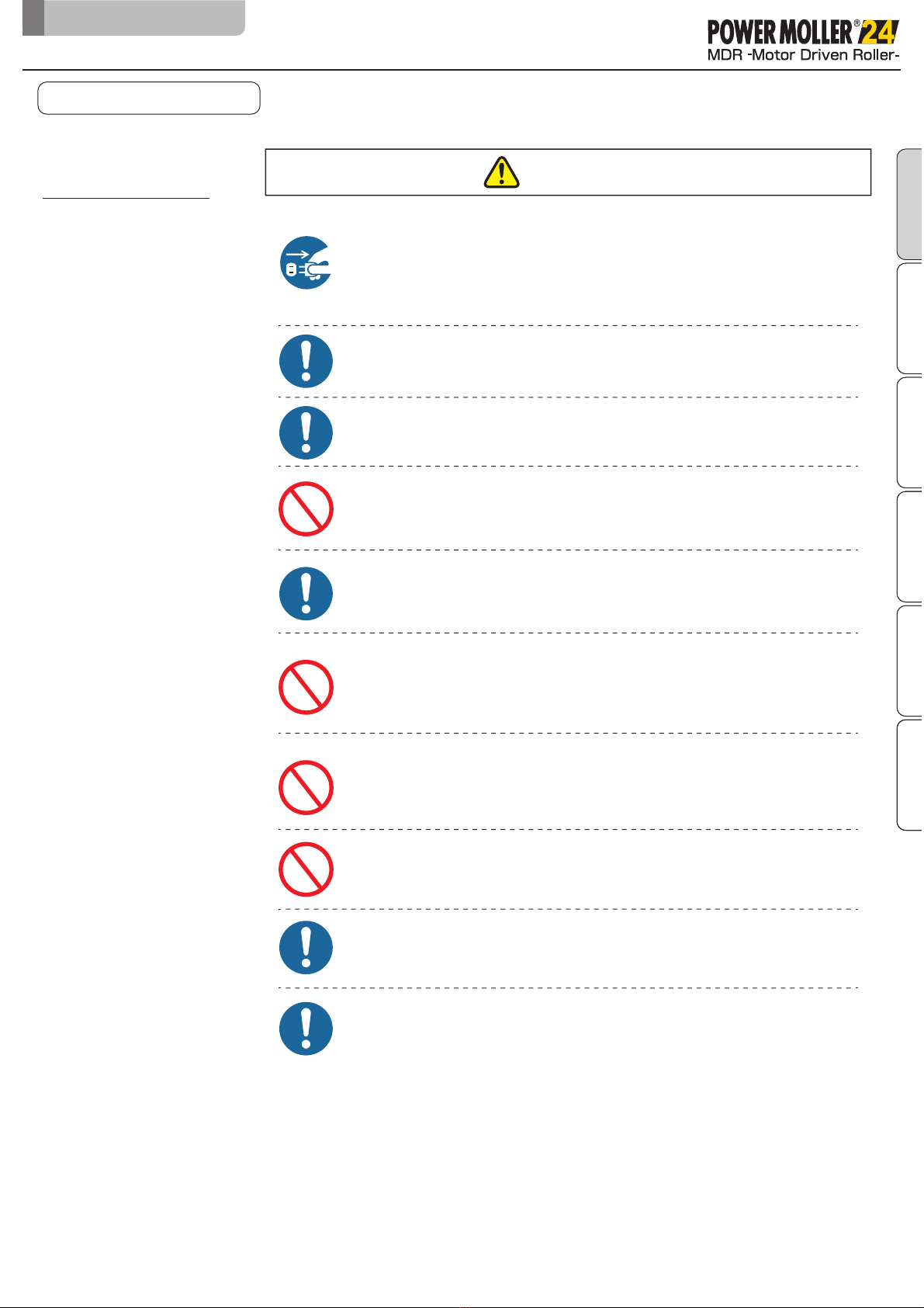
Stop operation when abnormal sound is heard during operation.
Failuretofollowthiscouldresultinunexpectedaccidents.
Do not use in a way exceeding the range of the product
specifications.
Failuretofollowthiscouldresultinmalfunction,fire,and/orinjury.
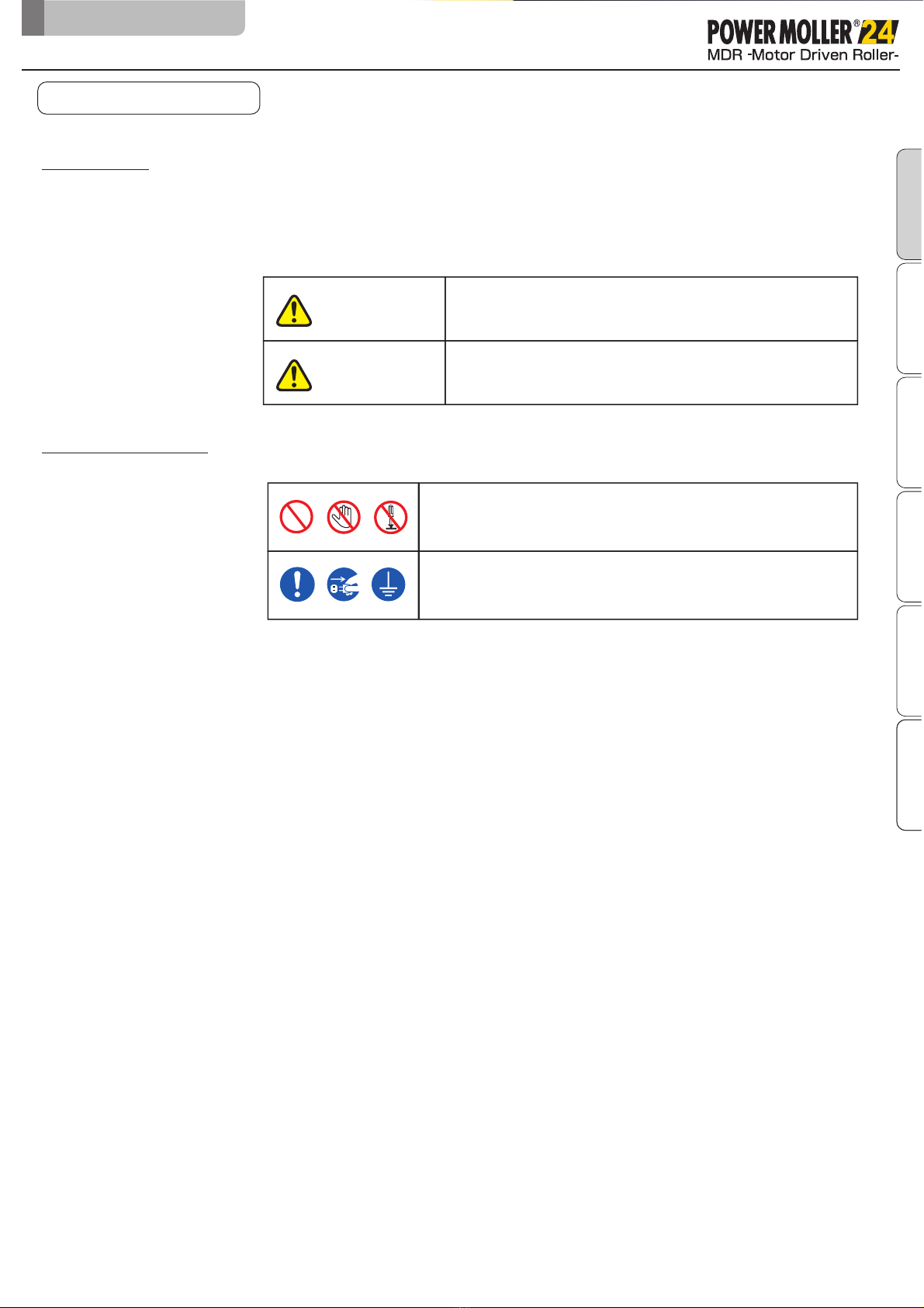
WARNING
CAUTION
Do not use the product near places subject to explosive,
flammable gas, and/or corrosive atmosphere, and/or
combustible materials.
Failure to follow this could result in explosion, fire, electric shock and/or
injury.
When using the product in places where serious accidents
and/or damage may possibly occur, install backup and/or
fail-safe functions systematically.
Failure to follow this could result in the inability to control this product due
to driver card malfunction, which could lead to serious accidents.
Do not forcibly bend and/or pull cables.
Also, do not put heavy materials on cables, or do not get them
stuck between cables.
Failure to follow this could result in fire and/or electric shock due to cable
damage.
Make sure to attach ground wires to the conveyor body and DC
power supply unit.
Failure to follow this could result in electric shock if any malfunction or leakage
occurs.
Never modify the product and/or driver cards.
Failure to follow this could result in serious accidents.
Do not touch the product when it is running or after it has just
stopped operation.
Failure to follow this could result in burns.
Do not put water and/or oil on the product, and do not transfer
wet and/or oily trays.
Failure to follow this could result in electric shock, and/or malfunction.
3-1.
General precautions
Do not apply strong impact and/or excessive force to the
product, such as hitting it with objects, or dropping it. Also, do
not use the equipment if strong impact has been applied, and/or
if the appearance has become deformed.
Failure to follow this could result in malfunction due to applied impact.
General precautions
3.Safety precautions
Safety precautions
Preparation Before Installation
Check productInstallation
Maintenance
Appendix
Original notice - A1.1

PM605KT/PM605KT-BTechnicaldocumentation
9
CAUTION
Observe the safety regulations required for installation locations,
and/or products in use.
Do not turn on/offrelays and/or contactors near power cables,
signal cables, and/or driver cards.
Failuretofollowthiscouldresultinmalfunctionduetonoisegeneration.
LED or Pull-up/Pull-down circuits implemented in the output
circuit of control devices could result in unexpected operation.
Carefullychecktheoutputcircuit.
Turn offthe power supply to the product before moving and/or
installing the product, and performing maintenance and
inspection (excluding those during operation).
Working while the power is on could result in accidents due to unexpected
operation.
Securely wire each cable to connection parts.
Improperwiringcouldresultinelectricshockand/ormalfunction.
Do not unplug power and/or signal cables during operation.
Also, do not run/stop this product by the power supply.
(Use the signal.)
Failuretofollowthiscouldresultinmalfunction.
Do not forcibly rotate the MDR at times other than maintenance
and inspection.
Failuretofollowthiscouldresultindamagetodrivercards, and/ortheirlifetime
tobesignificantlyshortened.
Do not shut offthe power during operation unless there is an
emergency.
Failuretofollowthiscouldresultinmalfunction.
3-1.
General precautions
General precautions
3.Safety precautions
Make sure to perform the start-up inspection, and check that
devices are free from any abnormalities, and that safety
equipment functions correctly before using the product.
When disposing of the product, make consigning contracts with
licensed industrial waste disposers, and consign the disposal to
them.
Safety precautions
Preparation Before Installation
Check productInstallation
Maintenance
Appendix Safety precautions
Preparation Before Installation
Check productInstallationAppendix
Original notice - A1.1

PM605KT/PM605KT-BTechnicaldocumentation
10
CAUTION
When handling, wear protective equipment, such as gloves.
Sincethisproductconsistsinlargepartofmetal,carelesshandlingcouldresult
inhandsgettinginjured.
Check the corresponding installing direction to the
loading/discharging sides before installing.
Failuretofollowthiscouldresultinobjects/bodypartsgettingcaughtand/or
stuck.
Never fail to use the dedicated mounting bracket supplied to
mount this product using the specified fastening torque.
Failuretofollowthiscouldresultinworkersgettinginjured orthedamagetothe
Product.
Make sure to use the recommended tightening torque to tighten
bolts for installing the mounting bracket.
Failuretofollowthiscouldresultinboltsand/orscrewsloosening,and/or
malfunction.
3-2.
Precautions on
installation
Precautions on installation
3.Safety precautions
Safety precautions
Preparation Before Installation
Check productInstallation
Maintenance
Appendix
If necessary warning/caution labels become hidden after installing
fences, affix again on places where they can be seen.
Allow a 2 to 5 mm gap between MDR and conveyor frame to
facilate the installation and removal.
Install the roller with the appropriate number of person according
to the product weight.
WARNING
CAUTION
Do not pull, tear or cut and then reconnect the power cables.
Failure to follow this could result in electric shock, fire or malfunction.
3-3.
Precautions on wiring
Perform wiring when the power is shut off.
Failure to follow this could result in electric shock and/or accidents due to
unexpected operation.
Never perform wiring in wet environment or with wet fingers.
Failure to follow this could result in leakage, short-circuit or fire.
Original notice - A1.1

PM605KT/PM605KT-BTechnicaldocumentation
11
Safety precautions
Preparation Before Installation
Check productInstallation
Maintenance
Appendix
WARNING
At the time of repair and replacement work, turn offthe power to
all connecting devices.
To prevent wraparound for the power circuits and/or signals, shut offthe power,
wait a sufficient amount of time, and discharge electricity inside the DC power
supply equipment.
At the time of maintenance and inspection, post warning labels
so as to prevent unauthorized persons from turning on the power.
Failuretofollowthiscouldresultinmalfunctionand/orunexpectedaccidents.
If any abnormalities are found, do not use this product until the
causes have been eliminated completely .
Have specialists (or people who have sufficiently acquired
skills) perform maintenance and inspection under
instructions by management supervisors.
Usingthisproductwithunattendedabnormalitiescouldresultinnotonly
damagetothedevices,butalsounexpectedaccidents.
3-4.
Precautions on
maintenance
Precautions on maintenance
CAUTION
3.Safety precautions
When repairing/replacing, wear protective equipment, such as
gloves.
Failure to follow this could result in hands getting injured by metal parts.
Do not disassemble sections and/or parts other than those
specified.
Failure to follow this could result in malfunction and/or unexpected accidents.
Make sure to prepare repair/replacement parts designated by
ITOH DENKI.
Using parts other than those designated by ITOH DENKI could result in
malfunction.
Original notice - A1.1

PM605KT/PM605KT-BTechnicaldocumentation
12
4.
PreparationBeforeInstallation
4.PreparationBeforeInstallation
Safety precautions
Preparation Before Installation
Check productInstallation
Maintenance
Appendix
Original notice - A1.1

PM605KT/PM605KT-BTechnicaldocumentation
13
4.Preparation Before Installation
Configuration example
PreparationBeforeInstallation
Equipment to feed 24V DC power source.
①24V DC power supply
Switched-mode power supply (24V DC)
24V DC battery
10A 240W per one PM605KT/PM605KT-B unit
■Switched-mode power supply for DC Power Supply (DC 24V ± 10%) is recom-
mended to be used for Driver Card
■Select the DC power supply with a sufficient capacity, over 24V DC, 10A, to
avoid power fluctuations.
■Make sure to use a power supply having a capacity larger than the rated input
of the dedicated driver card, multiplied by the number of MDR connected. If
the capacity of the power supply is insufficient, it may cause supply voltage
drop resulting malfunction or damage.
Note: In case multiple MDR start running simultaneously, power supply capacity
should not be less than 10A x number of MDR.
■Select an isolated switched-mode power supply conforming to safety
standard rated IEC60950-1 and/or UL60950-1. Do not use non isolated
type power supply for safety reasons and for radiation noise restrictions.
■Use of transformer type power supply is prohibited.
■Verify that the suppliedvoltage is stable at DC24V ± 10% at terminal for the
Driver card.
■Select a power supply with a protective mechanism that will not trigger below
30A-1msec peak current.
■Safety circuit should include emergency stop button and magnetic contact
switches.
CBK-109
24VDC
PowerSupply
SafetyCircuit
CircuitBreaker
ACPower
Source
■The number(s) of input and output signals to and from the driver cards
should match your operation design.
MDR
PLC/Controller
Unit
Prior to installation, following components and devices need to be prepared by
the customer.
Components and devices
to be provided by the
customer.
(Not included with this
product)
Safety precautions
Preparation Before Installation
Check productInstallation
Maintenance
Appendix
Original notice - A1.1

PM605KT/PM605KT-BTechnicaldocumentation
14
4.Preparation Before Installation
PreparationBeforeInstallation
②Driver card
Control equipment such as PLC for Driver cards.
③Control equipment
④Safety relay
Safety precautions
Preparation Before Installation
Check productInstallation
Maintenance
Appendix
Original notice - A1.1
⑤24VDC power supply Reference Input
CT-10-241
380~480V
3 ph
QT-20-241
QT-40-241
Output
24V-10A
24V-20A
24V-40A
Power
240W
480W
960W
Start-up boost
120%
150%
150%
- Very weak inrush current
- Accepts excess current of 120 to 150% at startup (according to model)
⑥24VDC distribution connector Connector
Reference PD-2P
21
35
24
- 32A max
- 2 pole with marking «24V / OV»
- 4 connector by pole
- Cable 0.5 -4.00mm (AWG...)
- Fixing with M3 bolt or screw
CBK-109、HBK-608、IB-E04、IB-P02
A driver card is required to control MDR operation.
CBK-109 HBK-608 IB-E04
(Standard driver)(
Built-in logic driver)(
EtherNet/IP based Controller)
*Mechanical brake option is compatible only with the CBK-109B driver card.
IB-P02
(Profinet based Controller)

⑦MDR extension cable
(Optional)
An extension cable is required when the distance between the MDR and the
driver card is longer than the MDR cable length.
■Total length of cable including cable on MDR must not be longer than 3000 mm.
■Do not use multiple extension cables per MDR.
■CBK-109 / HBK-608 IB-E04 IB-P02 12P Extension cable
// :
■CBK-109:13P Extension cable(for Mechanical brake option)
60
L
±5
Male side
Male side
Female side
Female side
37
60
L
±5
37
37.5
40
φ5.5
φ5.5
PM605KT/PM605KT-BTechnicaldocumentation
15
4.Preparation Before Installation
PreparationBeforeInstallation
Safety precautions
Preparation Before Installation
Check productInstallation
Maintenance
Appendix
Original notice - A1.1
Part number
13 Pin extension cable length
ACE-CBK-H1000 L= 1000mm
Part number
12 Pin extension cable length
ACE-CBM-G1200 L= 1200mm
ACE-CBK-H2000 L= 2000mm
ACE-CBM-G2000 L= 2000mm

⑧
Ribbed belt
(Optional)
PM605KT/PM605KT-BTechnicaldocumentation
16
4.Preparation Before Installation
Ribbedbelt
Refer to CBK-109 technical documentation for emergency stop.
⑨Emergency Stop Device
Select the circuit breaker according to the capacity of your 24V DC power supply.
Selecting the proper circuit breaker will provide additional protection to overflow current
situation.
When selecting earth leakage breaker, select inverter compatible type. Some non-
inverter type may incorrectly respond to the high frequency component of the switching
power supply as earth leakage.
When the 24VDC power supply unit has been installed, check that the circuit breaker
and emergency stop switch function properly. Perform operation according to the
following steps.
1) Input to the DC power supply is securely turned ON and OFF when turning ON and
OFF the breaker.
2) Input to this Product (24V DC) is securely turned ON and OFF when turning the
emergency stop switch OFF and ON.
⑨-1Circuit breaker
check points
⑨-2Device Operation
Test
Safety precautions
Preparation Before Installation
Check productInstallation
Maintenance
Appendix
Original notice - A1.1
Pitch between the rollers
(mm)
For pulley Ø56mm
60-63
6
4
Ref. 4PJ302-56
Number of teeth
67-70
71-74
77-80
83-87
94-99
100-101
103-107
109-114
122-127
130-135
136-141
150-156
175-182
188-195
234-238
285-289
Ref. 6PJ302-56
Ref. 4PJ314-56 Ref. 6PJ314-56
Ref. 4PJ316-56 Ref. 6PJ316-56
Ref. 4PJ336-56 Ref. 6PJ336-56
Ref. 4PJ346-56 Ref. 6PJ346-56
Ref. 4PJ372-56 Ref. 6PJ372-56
Ref. 4PJ376-56 Ref. 6PJ376-56
Ref. 4PJ388-56 Ref. 6PJ388-56
Ref. 4PJ416-56 Ref. 6PJ416-56
Ref. 4PJ436-56 Ref. 6PJ436-56
Ref. 4PJ442-56 Ref. 6PJ442-56
Ref. 4PJ456-56 Ref. 6PJ456-56
Ref. 4PJ486-56 Ref. 6PJ486-56
Ref. 4PJ536-56 Ref. 6PJ536-56
Ref. 4PJ570-56 Ref. 6PJ570-56
Ref. 4PJ636-56 Ref. 6PJ636-56
Ref. 4PJ746-56 Ref. 6PJ746-56
Pitch Pitch

PM605KT/PM605KT-BTechnicaldocumentation
17
5. Checkproduct
5.Checkproduct
Safety precautions
Preparation Before Installation
Check product
Installation
Maintenance
Appendix
Original notice - A1.1

PM605KT/PM605KT-BTechnicaldocumentation
18
5.Check product
Checking the model Open the package, and verify the product part number matches what you ordered.
MDR
Checkproduct
Mountingbracket
(SeePage19)
Locationof
partnumberindication
Cable
Safety precautions
Preparation Before Installation
Check productInstallation
Maintenance
Appendix
Original notice - A1.1
Round label
I
T
O
H
D
E
N
K
I
P
M
6
0
5
K
T
0
5
5
0
8
0
0
X
V
0
S
C
0
0
1
1
0
/
1
4
1
1
5
1
/
0
1
0
I
P
5
4
2
4
V
D
C
5
5
m
/
m
n
S
1
1
2
3
4
5
6
7
1
2
3
4
5
6
7
Product reference number
Month and year of shipment
Serial number
Protection index
Power supply
Speed
Operation
Square label 1
2
3
4
5
6
7
8
Product reference number
Month and year of shipment
Serial number
Protection index
Power supply
Nominal intensity
Absorbed power
Speed
Operation
9

PM605KT/PM605KT-BTechnicaldocumentation
19
5.Check product
Visual validation ①Verify the MDR product has no scratch, dent, residue, corrosions (rust etc.)
②Verify there is no missing parts such as screws etc.
NOTE : Should any irregularity be found, contact the vendor immediately.
Verify accessories
Mounting bracket
Mounting bracket
Mounting bracket
Cable side shaft
Checkproduct
■Use only the hex bolts contained in the package.
Ref : MBK-0K1
6
51
35
65
43
8
2- 8.6
1 pce
1 pce 1 pce
2 pcs
2 pcs
2 pcs
2 pcs
2 pcs
50
35
13
4-C1
2-M8
6
Spring-loaded shaft
(non cable side)
Ref : MBK-0K1-7
Hex bolt M8 x 25
Strengthening category 10.9
Spring washer: M8
Toothed washer nut: M8
35
51 16
42.78.3
65
73
9
Spring washer
Hex bolt M8 x 25
2- 8.3
Hex socket head cap bolt:M8×25
Spring washer: M8
D-35 (Dedicated nut)
Safety precautions
Preparation Before Installation
Check product
Installation
Maintenance
Appendix
Original notice - A1.1
(Optional)
6
51
35
65
43
8
2- 8.6
Mounting bracket Ref : MBK-0K1-6W
2 pcs
(for IP65)
2 pcs
2 pcs
2 pcs
Hex bolt M8 x 25
Strengthening category 10.9
Spring washer: M8
Toothed washer nut: M8
Ref : MBK-0K1-7W
(for IP65)

PM605KT/PM605KT-BTechnicaldocumentation
20
6.Installation
6.Installation
Safety precautions
Preparation Before Installation
Check product
Installation
Maintenance
Appendix
Original notice - A1.1
This manual suits for next models
1
Table of contents
Other ITOH DENKI Industrial Equipment manuals

ITOH DENKI
ITOH DENKI POWER MOLLER 24 F-RAT-U225 User manual

ITOH DENKI
ITOH DENKI POWER MOLLER 24 F-RAT-S300 User manual

ITOH DENKI
ITOH DENKI F-RAT-S300 Series User manual

ITOH DENKI
ITOH DENKI F-RAT-NX75 User manual

ITOH DENKI
ITOH DENKI F-RAT-NX75 User manual

ITOH DENKI
ITOH DENKI MABS User manual

ITOH DENKI
ITOH DENKI F-RAT-U225 Series User manual

ITOH DENKI
ITOH DENKI POWER MOLLER IB-P03 Guide

ITOH DENKI
ITOH DENKI MABS User manual

ITOH DENKI
ITOH DENKI POWER MOLLER 24 Pop-D Divert User manual