ITRON Intelis User manual

Intelis Gas Meter
Proving and Setup
Guide
knowledge to shape your future
815-0154-00 REV 000 Itron, Inc. Page 1 of 66
REFERENCE GUIDE
08 July 2020

Intelis Gas Meter Proving and Setup Guide
08 July 2020
815-0154-00 REV 000
Copyright © 2020 Itron, Inc. All rights reserved.
Confidentiality Notice
Confidential Information of Itron®, Inc., provided under nondisclosure obligations. The information
contained herein is proprietary and confidential and is being provided subject to the condition that (i) it be
held in confidence except to the extent required otherwise by law and (ii) it will be used only for the
purposes described herein. Any third party that is given access to this information shall be similarly bound
in writing.
Trademark Notice
Itron is a registered trademark of Itron, Inc.
All other product names and logos in this documentation are used for identification purposes only and may
be trademarks or registered trademarks of their respective companies.
For more information about Itron or Itron products, go to www.itron.com.
If you have questions or comments about a software or hardware product, contact Itron Technical Support
Services.
Contact
Email: support@itron.com
Itron Access: https://access.itron.com
Telephone Itron Technical Support North America: 1-877-487-6602
For technical support contact information by region, go to www.itron.com and select your country and
language.
08 July 2020 815-0154-00 REV 000 Itron, Inc. Page 2 of 66
Intelis Gas Meter Proving and Setup Guide

Contents
In telisGa s Me terPro v ing a n d Se tup Gu ide 1
Con ten ts 3
New inthis Do c u me n t 5
1 Important Safety and Compliance Information 6
USA, FCC Part 15 Spectrum Compliance 6
USA, FCC Class B-Part 15 6
Modifications and Repairs 6
Canada, ISED Spectrum Compliance 7
RF Exposure (FCC/ISED) 7
Australia, ACMA Spectrum Compliance 7
Electromagnetic Compatibility 7
Intrinsic Safety 7
Lithium Battery 8
Transportation Classification 8
Electrostatic Discharge 8
Electrostatic Ignition Hazard 8
Device Cleaning 8
Do Not Drop 8
Product Standards 9
2 Overview 10
Related Documents 11
Specifications 11
Dimensions 13
3 Proving 15
Prover Station 15
Test Mode 15
Entering Test Mode 17
Recording Test Mode Consumption 17
Exiting Test Mode 17
Prover Types 18
08 July 2020 815-0154-00 REV 000 Itron, Inc. Page 3 of 66

4Proving the Intelis Gas Meter Using the Honeywell SNAP Proving
System 19
Tempering the Meter by Exercising 20
Setting Up the Prover 21
Proving the Intelis Gas Meter 26
5Proving the Intelis Gas Meter Using the Measurement Systems Proving
System 31
Temper the Meter by Exercising the Meter 33
Setting Up the Measurement Systems Prover 34
Proving the Intelis Gas Meter 45
6Proving the Intelis Gas Meter Using the Energy Economics (EEI) Proving
System 48
Temper the Meter by Exercising the Meter 50
Setting Up the EEI Prover 52
Proving the Intelis Gas Meter 57
7 Calibrating the Intelis Gas Meter 59
Adjusting the Calibration 59
To Adjust the Calibration of an Intelis Gas Meter 60
To Seal an Intelis Gas Meter 63
To Unseal an Intelis Ggas Meter's UMU 65
08 July 2020 815-0154-00 REV 000 Itron, Inc. Page 4 of 66
Intelis Gas Meter Proving and Setup Guide Table of Contents

New in this Document
Revision Date Description
REV 000 July 2020 Original publication date.
Note:The content in this document used to be part of the Intelis Gas
MeterInstallation Guide, which has since been redacted and merged with the
Intelis Gas Meter Technical Reference Guide.
08 July 2020 815-0154-00 REV 000 Itron, Inc. Page 5 of 66
Intelis Gas Meter Proving and Setup Guide Table of Contents

1
Important Safety and Compliance Information
This section provides important information for your safety and product compliance.
USA, FCC Part 15 Spectrum Compliance
This device complies with Part 15 of the FCC Rules. These limits are designed to provide
reasonable protection against harmful interference in a residential installation.
Operation is subject to the following two conditions:
■This device may not cause harmful interference.
■This device must accept any interference that may cause undesirable operation.
This device must be installed to provide a separation distance of at least 20 centimeters (7.9
inches) from all persons to be compliant with regulatory RF exposure.
USA, FCC Class B-Part 15
This equipment has been tested and found to comply with the limits for a Class B digital device,
pursuant to Part 15 of the FCC Rules. These limits are designed to provide reasonable
protection against harmful interference in a residential installation. This equipment generates,
uses, and can radiate radio frequency energy and, if not installed and used in accordance with
the instructions, may cause harmful interference to radio communications. However, there is no
guarantee that interference will not occur in a particular installation. If this equipment does cause
harmful interference to radio or television reception, which can be determined by turning the
equipment off and on, the user is encouraged to try to correct the interference by one or more of
the following measures:
■Reorient or relocate the receiving antenna.
■Increase the separation between the equipment and receiver.
■Connect the equipment into an outlet on a circuit different from that to which the receiver is
connected.
■Consult the dealer or an experienced radio or TV technician for help.
Modifications and Repairs
To ensure system performance, this device and antenna shall not be changed or modified
without the express approval of Itron. Per FCC rules, unapproved modifications or operation
beyond or in conflict with these instructions for use could void the user's authority to operate the
equipment.
08 July 2020 815-0154-00 REV 000 Itron, Inc. Page 6 of 66

Canada, ISED Spectrum Compliance
Compliance Statement Canada Déclaration de Conformité
This device complies with Innovation, Science and
Economic Development Canada (ISED) license-exempt
RSS standard(s). Operation is subject to the following two
conditions: (1) this device may not cause interference, (2)
this device must accept any interference, including
interference that may cause undesired operation of the
device.
Under Innovation, Science and Economic Development
Canada (ISED) regulations, this radio transmitter may only
operate using an antenna of a type and maximum (or
lesser) gain approved for the transmitter by Industry
Canada. To reduce potential radio interference to other
users, the antenna type and its gain should be so chosen
that the equivalent isotropically radiated power (e.i.r.p.) is
not more than that necessary for successful
communication.
Le présent appareil est conforme aux CNR d'Industrie
Canada applicables aux appareils radio exempts de
licence. L'exploitation est autorisée aux deux conditions
suivantes: (1) l'appareil ne doit pas produire de brouillage,
(2) l'utilisateur de l'appareil doit accepter tout brouillage
radioélectrique subi, même si le brouillage est susceptible
d'en compromettre le fonctionnement.
Conformément à la réglementation d'Industrie Canada, le
présent émetteur radio peut fonctionner avec une antenne
d'un type et d'un gain maximal (ou inférieur) approuvé pour
l'émetteur par Industrie Canada. Dans le but de réduire les
risques de brouillage radioélectrique à l'intention des
autres utilisateurs, il faut choisir le type d'antenne et son
gain de sorte que la puissance isotrope rayonnée
équivalente (p.i.r.e.) ne dépasse pas l'intensité nécessaire
à l'établissement d'une communication satisfaisante.
RF Exposure (FCC/ISED)
This equipment complies with radiation exposure limits
set forth for an uncontrolled environment. This equipment
should be installed and operated with minimum distance
20 cm between the radiator and your body. This
transmitter must not be co-located or operating in
conjunction with any other antenna or transmitter.
Cet équipement est conforme aux limites d'exposition aux
radiations dans un environnement non contrôlé. Cet
équipement do it être installé et utilisé à distance minimum
de 20 cm entre le radiateur et votre corps. Cet émetteur ne
doit pas être co-localisées ou opérant en conjonction avec
tout autre antenne ou transmetteur.
Australia, ACMA Spectrum Compliance
When this device is sold and shipped to Australia, it is configured and labeled accordingly to be
compliant with ACMA Standards for the Radio, EMC and RF Exposure. This includes standard
AS/NZS 4268 RF spectrum standard for frequency and power out.
Electromagnetic Compatibility
Warning! Use only approved accessories with this equipment. All cables must be
high quality, shielded, and correctly terminated. Unapproved modifications or
operation beyond or in conflict with these use instructions may void the authority's
authorization to operate the equipment.
Intrinsic Safety
Warning! Substitution of components may impair intrinsic safety.
08 July 2020 815-0154-00 REV 000 Itron, Inc. Page 7 of 66
Intelis Gas Meter Proving and Setup Guide 1 Important Safety and Compliance Information
Lithium Battery
Warning! Follow these procedures to avoid injury to yourself or others.
■The lithium battery may cause a fire or chemical burn if it is not disposed of properly.
■Do not recharge, disassemble, heat above 212°Fahrenheit (100°C Celsius), crush, expose
to water, or incinerate the lithium battery. Fire, explosion, and severe burn hazard.
■The battery used in this device may present a risk of fire or chemical burn if mistreated.
■Keep the lithium battery away from children.
Transportation Classification
The Federal Aviation Administration prohibits operating transmitters and receivers on all
commercial aircraft. When powered and not in Factory ship mode, the Itron device is considered
an operating transmitter and receiver and cannot be shipped by air. All product returns must be
shipped by ground transportation.
Electrostatic Discharge
Warning! Internal circuit components can be sensitive to electrostatic discharge.
Before installation, discharge electrostatic buildup by touching a metal pipe or other
earth-grounded metal object prior to touching the meter body, register housing, or
Itron device.
Electrostatic Ignition Hazard
Warning! Verify the area is not hazardous when installing, servicing, cleaning, or
touching the Itron device.
Device Cleaning
Warning! Clean only with a damp cloth.
Do Not Drop
Warning! While Itron meters are designed to withstand a drop, dropping the meter
may damage the device, impact the meter accuracy, and void the warranty.
08 July 2020 815-0154-00 REV 000 Itron, Inc. Page 8 of 66
Intelis Gas Meter Proving and Setup Guide 1 Important Safety and Compliance Information

Product Standards
These instructions are not intended to replace any utility or company-established meter
installation procedures. These instructions are provided for additional information. The meter
installation must comply with all country, state, and local building and safety regulations as well
as federal regulations including Section 192.353 of Title 49 of the Code of Federal Regulations.
Two pertinent paragraphs of the code are:
■Each meter and service regulator, whether inside or outside of a building must be in a readily
accessible location and be protected from corrosion and other damage.
■Each meter installed within a building must be located in a ventilated place and not less than
3 feet from any source of ignition or any source of heat which might damage the meter.
The Intelis Gas Meter is rated for the following operating and storage temperature ranges. Use
of the meter outside of the listed temperature ranges is not recommended.
■Operating ranges:
–Measurement: -30° F (-34° C) to +131° F (55° C)
–Valve: -13° F (-25° C) to +131° F (55° C)
–RF: -40° F (-40° C) to +158° F (70° C)
■Storage range:
–-40° F (-40° C) to +158° F (70° C)
■Direct inquiries as to the selection and application of gas meters to your local Itron sales
representative or Itron Support.
■Itron does not endorse or warrant the completeness or accuracy of any third-party meter
installation procedures or practices, unless otherwise provided in writing by Itron.
–Follow your company's standard operating procedures regarding the use of personal
protection equipment (PPE).
–Adhere to guidelines issued by your company in addition to those given in this document
when installing or repairing meters.
08 July 2020 815-0154-00 REV 000 Itron, Inc. Page 9 of 66
Intelis Gas Meter Proving and Setup Guide 1 Important Safety and Compliance Information
2
Overview
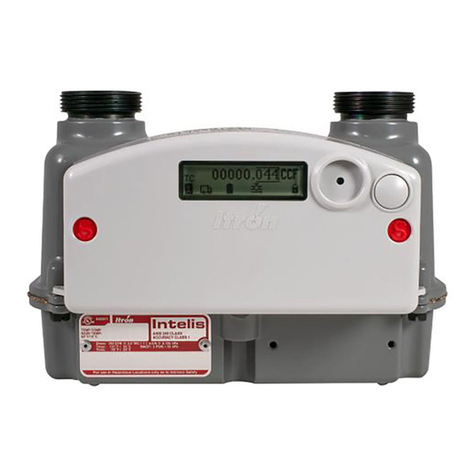
The Intelis Gas Meter is a solid state ultrasonic smart meter equipped with the following features:
■High flow alarm with optional automatic valve shutoff
■High temperature alarm with an optional automatic valve shutoff
■Built in temperature conversion
■Integrated RFcommunications module
■Air detection
■Reverse flow detection
The internal automatic safety shutoff valve can be configured to function similarly to an excess
flow valve downstream of the meter. The meter delivers distributed intelligence to gas metering
by providing the ability to self-monitor and close the valve during a high flow incident.
Weighing in at 4-1/2 pounds, this 250 cubic-feet-per-hour (CFH) residential gas meter with 6
inch center-to-center hub connections mounts easily within existing meter footprints for simple
meter installation and replacement of existing gas meters. An integrated communications
module enables 100S Mobile Mode with mobile reading systems or OpenWay Riva Network
Mode based on IPv6 standards that allow users to migrate to AMR or AMI systems.
08 July 2020 815-0154-00 REV 000 Itron, Inc. Page 10 of 66

Caution: Always follow your company's procedures for gas meter installation and
operation.
Related Documents
For more information about the Intelis Gas Meter and compatible system architecture
documentation, see your product's documentation. The following table lists documentation that
might be relevant to the setup of your meter. All Itron product documentation can be located and
accessed through https://access.itron.com/.
Note: Where the part number is not specifically listed below, refer to the documentation that
matches your version of the indicated product.
■Intelis Gas Meter Ordering Guide (815-0335-00)
■Intelis Gas Meter Technical Reference Guide (815-0119-00)
■Intrinsic Safety ControlDrawing for Index Module Replacement of Itron Model Intelis Gas
Meter (TDC-0978-009)
■Replacing Batteries in the Itron Intelis Gas Meter (TDC-978-011)
■Intelis Gas Meter Specification Sheet (101584SP)
■Field Deployment Manager Mobile Application Guide
■Field Deployment Manager Tools Application Guide
■Field Deployment Manager Tools Configuration Guide
■Itron Security Manager User Guide
■OpenWay Operations Center Collection Manager Device Interface Guide
Specifications
The following table lists the Intelis Gas Meter product specifications.
Specification Specification value
Meter capacity 250 CFH at ½ w.c. / 7.1 m3/h @0.125 kPa
Measurement principle Ultrasonic time of flight
Accuracy Class 1 and ±0.5% at room temperature
Meter type Temperature compensated (TC) or non-temperature compensated (NTC)
Hub center-to-center 6 inches (152.4 mm)
Hub size options ■10LT
Table 1Intelis Gas Meter specifications
08 July 2020 815-0154-00 REV 000 Itron, Inc. Page 11 of 66
Intelis Gas Meter Proving and Setup Guide 2 Overview

Specification Specification value
■20LT
■30LT
■1A/Sprague standard
■1-1/4", 1" Pittsburgh
■ISO G 1-1/4"
Meter MAOP 5 PSIG (35 kPa)
Valve Actuated swing valve, maximum 0.035 CFH (1 L/H) leakage rate
LCD displayed units CCF (100 x cubic foot) or cubic meter
LCD resolution 00000.001 CCF (0.1 CF) or 00000.001 m3
Case Aluminum case with ASA 49 gray powder coat finish
Weight 4.5 lbs (2.0 kg)
Gas type ■Natural gas Type H, E, L (per EN 437)
■Reference gases G20, G21, G23, G25, G26, G27
Component materials ■UMU (ultrasonic measuring unit): polybutylene terephthalate (PBT) and
polycarbonate (PC)
■Valve plastics: PBT
■Inlet and outlet tubes: polyoxymenthylene (POM)
Intrinsically safe For use in Class I, Division 1, Group D hazardous locations.
Temp Code T1 -40°C ≤ Ta ≤ +70°C
IECEx UL 18.0144X Ex ia IIA T1 Ga
Regulatory ■FCC: Part 15.247, Part 15.249 (programming)
■FCC ID: EWQINTELISG
■Innovation, Science, and Economic Development Canada (ISED): RSS-247 and
RSS-210 (programming)
■IC ID: 864D-INTELISG
■Measurement Canada: Pending
Operational All Intelis Gas Meters operate without the need for an FCC or ISED license.
■Frequency: 902-928 MHz ISM band
■Program frequency: 908-923.8 MHz
Australia ■ACMA AS/NZS 4268
■Frequency: 915-928 MHz ISM band
■Program frequency: 916-926.8 MHz
Operating temperature ratings ■Measurement: -30° F (-34° C) to +131° F (55° C)
Table 1Intelis Gas Meter specifications (continued)
08 July 2020 815-0154-00 REV 000 Itron, Inc. Page 12 of 66
Intelis Gas Meter Proving and Setup Guide 2 Overview

Specification Specification value
■Valve: -13° F (-25° C) to +131° F (55° C)
■RF: -40° F (-40° C) to +158° F (70° C)
■LCD:-40F(-40C)to 185F(85C)1
Storage temperature ratings -40° F (-40° C) to +158° F (70° C)
Battery information 4 Lithium manganese dioxide (LiMnO2) 'A' cell batteries, replaceable
Battery life 20 years for meter, RF, and valve using recommended operating parameters
Badging Standard aluminum manufacturing and optional customer badge
Test pulse weight (volume per
pulse)
0.10CF, 0.25CF, 0.50CF, 1.0CF, 10dm3, 50dm3
Test pulse width 10 ms - 1000 ms (1 second)
Minimum compatible
collection software for Mobile
and Riva network
■FCS v4.1
■FDM Tools v4.2
■ISM v3.6 (if using enhanced security)
■Itron Mobile v1.5
■Mobile Collection v3.8.2
Minimum compatible
collection software for Gen5
network
■Gen3, 4, or 5 constantly powered device (CPD) hardware running UtilOS v5.0
■FCSv4.3.1
■FDM Tools v4.3
■ISM 4.2
■UtilityIQ v4.15
Standards Designed in compliance with ANSI B109.1, ANSIB109.0 (draft), and Measurement
Canada PS-G-06
Table 1Intelis Gas Meter specifications (continued)
1Electro-optical characteristic and optical performance is affected during high temperature
operation (approximately 176°F/80°C to 185°F/85°C) and low temperature operation
(approximately -22°F/-30°C to -40°F/-40°C). Performance recovers under normal temperature
range.
Dimensions
This section lists the Intelis Gas Meter dimensions. Dimensions are listed in Imperial and Metric
units.
08 July 2020 815-0154-00 REV 000 Itron, Inc. Page 13 of 66
Intelis Gas Meter Proving and Setup Guide 2 Overview

A B C D E F G
8.4 inches 6.4 inches 6.0 inches 5.4 inches 3.1 inches 9.1 inches 1.9 inches
214.4 mm 161.9 mm 152.4 mm 138.3 mm 78.6 mm 230.6 mm 48.8 mm
Table 2Intelis Gas Meter dimensions
Note: B dimension can vary with different hubs options. (20LT is shown).
08 July 2020 815-0154-00 REV 000 Itron, Inc. Page 14 of 66
Intelis Gas Meter Proving and Setup Guide 2 Overview

3
Proving
This section provides information about proving the Intelis Gas Meter. Meteorological proving
allows users to test the Intelis Gas Meter accuracy. Temper meters unpackaged in the proving
area for 24 hours prior to the testing.
Warning! Follow your company's standard operating procedures regarding the use
of personal protection equipment (PPE). Adhere to guidelines issued by your
company in addition to those contained in this document when proving meters.
The Intelis Gas Meter Test Mode and a prover station are used to confirm the accuracy of the
meter. Proving the Intelis Gas Meter requires attaching the pulse output prover cable between
the meter and the proving station. After the test is complete, the proving cable is removed and
the meter returns to normal operation.
Note: The Intelis Gas ultrasonic meter is highly accurate and sensitive to air flow. The meter
displays registration to 0.001 CCF. The meter sensitivity makes it possible to see the index
incrementing even with the hub caps in place.
For documentation information, see Related Documents on page 11.
Prover Station
The prover station captures and counts pulses from a pulse output proving cable. Each pulse
reflects a specific volume (pulse weight) of gas measured by the meter. Pulse width is a length of
time for the pulse. Both pulse width and pulse weight are configurable parameters using FDM.
The Intelis Gas Meter pulse weight must match the prover setup as described in this section's
proving instructions.
Test Mode
The Intelis Gas Meter cannot be programmed (configured) or calibrated while the meter is in
Test Mode. You must exit Test Mode to program or configure the meter. Attempting to program
or configure parameters while the meter is in Test Mode will result in a temporary error. If the
valve icon is blinking, the meter is unable to go into Test Mode. Wait a few minutes and try again.
Note: If the valve icon is blinking, the meter is unable to go into Test Mode. Wait a few
minutes and try again.
08 July 2020 815-0154-00 REV 000 Itron, Inc. Page 15 of 66

Test Mode is used in a meter shop or by a regulatory body. Some meter configuration and prover
setup are required for the prover to properly interpret the meter pulses. Meter configuration is
completed using FDM.
Proving accessory Itron part number
Honeywell SNAP pulse output prover cable CFG-7100-100
Measurement Systems pulse prover cable CFG-7100-500
Energy Economics (EEI) pulse prover cable CFG-7100-400
Can-Tronics pulse prover cable CFG-7100-200
Itron BPG SONICAL SN G6 pulse prover cable CFG-7100-700
Intelis Gas Meter proving stand FIX-7100-001
Table 3Accessory name and part number
You must exit Test Mode to program Test Mode parameters. Attempting to program Test Mode
parameters while the meter is in Test Mode will result in a temporary error. The configurable
parameters for Test Mode are listed in the table below.
Parameter Default Range
Pulse width 150 ms. 10 ms–1000ms (1 second)
Pulse weight 0.25 cf/pulse ■0.10CF
■0.25CF
■0.50CF
■1.0CF
■10dm3
■50dm3
Maximum Test Mode time 1 hour
Important:The Intelis Gas Meter will
automatically time out after 1 hour in
Test Mode whether there is activity or
not.
1–255 hours (whole numbers only)
Table 4Test Mode configurable parameters
Test Mode configuration can be completed at the factory at the time the meter is manufactured.
Parameters are configured in one of three ways:
■Through a custom programming file.
■Through programmed default configuration.
■In the field using FDM Tools.
08 July 2020 815-0154-00 REV 000 Itron, Inc. Page 16 of 66
Intelis Gas Meter Proving and Setup Guide 3 Proving

Note: Refer to the instructions for your prover type in the following sections for the
recommended Test Mode pulse width and pulse weight parameters.
Entering Test Mode
Entering Test Mode is accomplished using either the FDM mobile client or through the magnet in
the prover connection end of the prover cable. After the Intelis enters Test Mode, the following
steps occur.
1. The Intelis Gas Meter logs an Entering Test Mode event.
2. The Intelis Gas Meter enters Test Mode.
3. The Intelis Gas Meter Test Mode index is reset to a zero reading.
4. The Intelis Gas Meter starts an optical pulse output.
Caution: There are some parameters that could result in the Intelis Gas Meter
constantly pulsing (such as a small pulse weight and a long pulse width with a high
flow rate.) Adjust the pulse width, the pulse weight, or flow rate as needed.
5. The Intelis Gas Meter LCD moves to Test Display Mode.
Recording Test Mode Consumption
While the Intelis Gas Meter is in Test Mode, the following occurs:
1. The Intelis Gas Meter records the Test Mode consumption in the Test Mode index register.
2. The Intelis Gas Meter continues to output an optical pulse.
Note: While the Intelis Gas Meter is in Test Mode, the LCD refresh rate is more frequent
than when the meter is operating in Normal Mode.
3. The Intelis Gas Meter continues to update the normal volume registers.
Exiting Test Mode
The Intelis Gas Meter exits Test Mode after it receives a command from the FDM mobile client,
after the proving cable is removed from the meter, or when the Test Mode timeout is reached.
The following operations occur when the Intelis Gas Meter exits Test Mode:
1. The Intelis Gas Meter logs an Exiting Test Mode event.
2. The Intelis Gas Meter ends the optical pulse output.
3. The Intelis Gas Meter LCD returns to normal display mode.
Note: Check the LCD display to verify the Intelis Gas Meter is no longer displaying
Menu.
08 July 2020 815-0154-00 REV 000 Itron, Inc. Page 17 of 66
Intelis Gas Meter Proving and Setup Guide 3 Proving

Prover Types
The Intelis Gas Meter compatible prover types are listed below. See the procedure for your
prover type. For questions about your specific prover type, see the manufacturer's prover
documentation.
■Honeywell SNAP
■Measurement Systems
■Energy Economics, Inc (EEI)Sonic Nine
■Can-Tronics (TBD)
■Itron BPGSONICAL SNG6 (TBD)
08 July 2020 815-0154-00 REV 000 Itron, Inc. Page 18 of 66
Intelis Gas Meter Proving and Setup Guide 3 Proving

4
Proving the Intelis Gas Meter Using the
Honeywell SNAP Proving System
This section provides the information to set up an Intelis Gas Meter using a Honeywell SNAP
proving system.
Note: Proving the Intelis Gas Meter requires Honeywell SNAP prover software .NET X.Y.
Temper meters unpackaged in the proving area for 24 hours prior to testing. If tempering is not
possible,follow the instructions described in Tempering the Meter by Exercising on page 20.
If the meters are tempered, continue to Setting Up the Prover on page 21.
Warning! Follow your company’s standard operating procedures regarding the use
of personal protection equipment (PPE). Adhere to guidelines issued by your
company in addition to those contained in this document when proving meters.
Adjust the proving table to accommodate the height of the Intelis Gas Meter. If necessary, use
the Intelis Gas Meter prover stand (Itron part number FIX-7100-001). Place the prover stand on
the prover table and set the meter on the stand. See the image below for reference.
Note: To hold the meter properly in place, the meter should be placed in the fixture such that
the meter flange is below the fixture's edge.
08 July 2020 815-0154-00 REV 000 Itron, Inc. Page 19 of 66

Itron recommends these Intelis Gas Meter Test Mode parameter settings when testing on the
Honeywell SNAP proving system:
■Test Mode pulse weight: 0.25 CF
■Test Mode pulse width: 150 ms
Tempering the Meter by Exercising
1. Log on to the prover as a Supervisor.
2. Select Special Functions.
3. Select Diagnostics (local).
08 July 2020 815-0154-00 REV 000 Itron, Inc. Page 20 of 66
Intelis Gas Meter Proving and Setup Guide
4 Proving the Intelis Gas Meter Using the Honeywell SNAP Proving
System
Other manuals for Intelis
1
Table of contents
Other ITRON Measuring Instrument manuals

ITRON
ITRON G10 User manual

ITRON
ITRON SL7000 IEC7 User manual

ITRON
ITRON EquaScan pMIURF Owner's manual

ITRON
ITRON Aquadis+ P1 User manual

ITRON
ITRON Intelis Gas Meter User manual

ITRON
ITRON Mobile Collector Lite User manual

ITRON
ITRON EM512 TYPE 700 JV1 User manual

ITRON
ITRON Intelis User manual

ITRON
ITRON DATTUS III Installation guide

ITRON
ITRON Delta User manual