are both below the waterline, to prevent water from
siphoning back into the Holding Tank, the discharge
hose must include a Vented Loop Fitting positioned at
least 8" above the water line at all angles of heel and
trim. If unfamiliar with the proper installation of a vented
loop fitting, consult a qualified marine plumber.
The location for the Holding Tank must provide a flat
mounting surface, for it to rest on, that is both level and
sturdy enough to support the weight of a full holding
tank. The approximate weights of full Holding Tanks are
as follows:
MODEL NO. DESCRIPTION WEIGHT
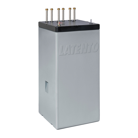
38110-Series Holding Tank & Macerator 10 Gal. 90 lb.
38120-Series Holding Tank & Macerator 20 Gal. 180 lb.
38140-Series Holding Tank & Macerator 40 Gal. 360 lb.
All Holding Tanks may be secured to the platform with
four machine or lag screws through the four slots in the
mounting point alcoves with either machine or lag
screws and flat washers. The 20 and 40 gallon Holding
Tanks may also be secured by strapping material
secured over the top of the tanks and positioned in the
strap grooves. The strapping material should be heavy-
duty fabric (such as nylon) or alternatively metal
strapping placed over padding to avoid abrasion.
PLUMBING
Each tank is fitted with a waste evacuation pick-up tube
with 1-1/2" (38mm) hose barb for connection to a dock-
side pump-out deck plate. Additionally, the top of the
tank includes a 1-1/2" hose barb to accept the toilet
discharge plumbing. It also has a 3/4" (19mm) hose barb
to accept the attachment of a tank vent. Holding Tank
vent fittings are generally installed high on a vessel’s hull
near the gunwale. The macerator discharge is a 1"
(25mm) hose barb and 1" (25mm) hose should be used
to connect to the overboard discharge thru-hull. It is a
good practice to clamp waste hoses using two stainless
steel band clamps at each connection.
ELECTRICAL
The electrical circuit must be independent of all other
accessories and made with marine grade stranded copper
wire. Determine the proper wire size for the electrical
circuit from the Electrical Specifications Chart based on
the total length of the circuit (both positive and negative
conductors). The positive conductor should be connected
to, and pick-up its power from, an overload protected
electrical distribution panel with the correct size circuit
breaker or fuse as determined from the Electrical
Specifications Chart. Connect both the positive and
negative conductors to the Holding Tank’s electrical buss
on top of the tank.
Determine an appropriate location for the Waste
Management Control Panel that will allow easy connection
of the panel with the HoldingTank using the system’s ten
foot wiring harness. Cover the mounting surface with
tape to protect it from damage when drilling and sawing
the panel clearance hole. Using the Control Panel
Mounting Template, mark the location of the holes to be
drilled with a 3/8 (10mm) drill and the material to be
removed with a saber saw plus the location of the four
corner mounting screws. Drill four 3/8 (10mm) diameter
corner holes and use a saber saw to remove material
from the mounting surface to provide clearance for the
panel’s electrical circuit board. Plug one end of the wiring
harness into the mating receptacle on the Holding Tank
and secure to the tank with the strain relief clips. Feed
the other end of the harness through the hole in the
panel’s mounting surface and plug it into the receptacle on
the rear of the Control Panel. Secure the Control Panel
to its mounting surface with four screws. It is
recommended that the wiring harness be secured with
wire ties to a solid mounting surface about every 18"
(45cm) along its length to prevent movement and abra-
sion.
ELECTRICAL SPECIFICATIONS
AMP FUSE WIRE SIZE PER FEET OF RUN*
VOLTAGE DRAW SIZE 0'-10' 10'-15' 15'-25' 25'-40' 40'-60'
12 Vdc 16 20 #12(4) #10(6) #10 (6) #8(10) #6(16)
24 Vdc 8 15 #16(1.5) #14(2.5) #12 (4) #10 (6) #10 (6)
*Length of run is total length of the circuit from the power source to product and back to
ground. Wire sizes listed are SAE guage and metric millimetres2.
MAINTENANCE
The Jabsco Waste Management System does not
require periodic or routine maintenance. However, it is
considered a good practice to occasionally flush the
system with a generous amount of clean water to flush
out any build-up of sludge or debris. To do this, simply fill
the tank to approximately 1/4 full with clean water either
by flushing a toilet or by adding water through the 3"
inspection port. Allow the water to slosh in the tank (from
normal boat motion while underway) for about five
minutes. Then, if operating in an area where it is legal to
discharge overboard (beyond the three mile limit in open
ocean waters and not in a designated “no discharge
zone”) pump the flush water from the tank or alternatively,
remove the flush water at a dockside pump-out facility.
The frequency of flushing depends on the vessels’ total
usage, but for most privately owned pleasure boats, once
a season is adequate cleaning. It may be convenient to
perform such flushing while preparing the vessel for an
off season lay up.
WINTERIZING
If the vessel is located in an area that experiences
freezing temperatures, the holding tank should be
“winterized” during cold weather periods. This can be
accomplished by removing all water possible from the
tank, either by the unit’sº Macerator evacuation pump
(where legal to do so) or at a dockside pump out facility.
Then add an amount of either alcohol or glycol based
antifreeze equal to about 5% of the tank’s total capacity
to the small amount of residual water that remains in
the tank.

