manuals.online logo
Brands
  1. Home
  2. •
  3. Brands
  4. •
  5. jablotron
  6. •
  7. Security Sensor
  8. •
  9. jablotron JA-169P User manual

jablotron JA-169P User manual

JABLOTRON ALARMS a.s.
Pod Skalkou 4567/33 46601 Jablonec n. Nisou
Czech Republic www.jablotron.com
||
|
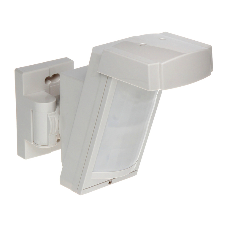
JA-169P outdoor dual PIR motion detector
JA-169P 1/2 MMY57100
This detector is a component of the JABLOTRON system. The JA-169P
dual wireless outdoor intruder detector is designed to detect human body
movement in an outdoor environment. The detector consists of JL01
detector produced by LINCE Italia S.r.l., and a JA-150TX-V1 transmitter
produced by JABLOTRON ALARMS. The optical part of the detector has
2 PIR sensors (dual zone detection) and a high immunity to false alarms and
detection of small animals. The detector is equipped with one tamper contact.
Tamper contact immediately reports any attempt on opening the detector or
demount from mounting place.
The detector should be installed by a trained technician with a valid
certificate issued by an authorised distributor.
Installation
Conditions:
1. The detector has to be installed onto a vertical wall (in a position
where its bottom surface is parallel to the guarded zone).
2. The detector should be installed 1–1.2 m above the ground.
3. The best movement detection is provided when the detection beams
intersect.
4. No other objects capable of causing detection interference (bushes,
trees, high grass, air-conditioners, etc.) should be situated in the field of
view of the detector.
5. Avoid direct effects of strong sources of light (sun reflections, etc.).
Procedure:
1. Unscrew the locking screw (1) on the bottom of the upper cover of
the detector and remove the detection part’s cover (3).
2. Unscrew seven screws which hold the detector´s main board (5) and
pull it out by tilting as you pull it out. There is a radio transmitter fitted
onto the rear side of the detector´s PCB.
3. Unscrew the 4 screws which link the rear cover (7) with the mounting
plate.
4. The detector can be mounted onto a level mounting place by the 4
screws through the mounting plate. Or it can be mounted on a pole
by metal ties (not supplied).
Warning: Do not touch the detector sensors
during handling
In case that physical contact does occur, it´s
necessary to clean the sensor with the use of
a cotton swab dipped in rubbing alcohol.
Fig. 1.: 1 – bracket screws, 2 – locking screw, 3 – front cover,
4 –adjustment knob for lower PIR (PIR2), 5 – PCB holder, 6 – tamper
contact 7 – mounting backplate
Enrolling the detector to the system
Signal transmitter for wireless communication is located underneath
the main board part of the detector. The battery is inserted into
the battery holder placed on the transmitter’s PCB.
Enrolment procedure to the system:
a. In the F-Link software, select the required position in the Devices
window and launch the enrolment mode by clicking on the “Enrol”
option.
b. Insert the batteries (mind the correct polarity). When the first battery
has been inserted into the battery holder an enrolment signal is
transmitted to the control panel and the detector is enrolled to the
selected position.
c. Assemble the detector in opposite order in which it was
disassembled.
Fig. 2 – Transmitter JA-150TX-VXI:1 – wire terminals, 2 – settings DIP
switch (pre-set from factory, see picture), 3 – external tamper contact
jumper, 4 – battery holder, 5 – external antenna jumper,
6 – external antenna connector
Notes:
−There must be a JA-11xR radio module installed in the control
panel.
−The detector can also be enrolled into the system by entering its
serial number (7) in the F-Link software. You can find the serial
number on the sticker, glued onto the PCB. All numbers under
the bar code has to be entered (1400-00-0000-0001).
−If needed the transmitter can be equipped with an AN-868 (2PIN)
external antenna connected to the connector (6) and disconnect
the jumper (5).
−For a DIP switch change of settings, the detector has to be
completely turned off.
Normal operation mode
The detector sends an activation radio signal when it is triggered.
In the case of tampering with the detector or tearing the detectoroff its
location, the detector sends a tamper signal. A status report is sent every
9 minutes to the control panel.
Checking and replacing the batteries
The detector checks the battery status automatically. Nearly drained
battery is reported by continuous flashing of yellow signalling LED on
the detector (1 flash per sec) and at the same time low battery status is
reported to the control panel. The detector remains fully functional.
The battery should be replaced as soon as possible.
The control panel must be in service mode before battery
replacement (see the control panel installation manual). Tamper
contact must be pressed several times after opening the cover and
removing the battery to discharge capacitors.
Setting up the optical part
of the detector
The optical part of the detector includes 2 PIR sensors with an optional
AND logic. They detect movement in two planes. The detecting angle of
the lower PIR sensor can be adjusted. The alarm signal is triggered only
if both detecting planes are triggered at the same time if the detector is
configured in such a way.
JA-169P outdoor dual PIR motion detector
JA-169P 2/2 MMY57100
The following table represents the values included in the figure:
Position
Maximum range of the lower detecting part
A
3 m
B
5 m
C
7 m
D
10 m
E
15 m
Table 1: Detection range
Warning:The maximum detection length of the lower detection plane
may vary from the values listed above due to varying environmental
thermal conditions. This must be taken into consideration during
detection range adjustment.
The detection area angle is 85°. Direction of the detection angle can
be adjusted to positions A – G by rotating the detector´s adjustment
knob. Each step is marked. The detector’s lens covers the angle of 180°
- therefore the lens does not require any adjustment.
The PIR detection sensitivity can be configured by a 10-pole switch
located next to the upper sensor.
DIP2
DIP3
PIR sensitivity
OFF
OFF
low
OFF
ON
low / medium
ON
OFF
medium / high
ON
ON
high
Table 2: PIR sensitivity
DIP4
DIP5
Working Logic
OFF
OFF
PIR1 - ON, PIR2 - ON
OFF
ON
PIR1 - ON, PIR2 - OFF
ON
OFF
PIR1 - OFF, PIR2 - ON
ON
ON
not available
Table 3: Working logic
The detector sends information to the control panel every 9 minutes.
For normal detector operation we recommend the LED indication to be
turned off in order to save battery life. The inhibition mode can be set by
DIP switch no. 9, selecting between 180 s and 30 s. It determines the
time period after which the detector is able to detect movement again
and send a new activation signal.
Testing (coverage test)
DIP switch Nº1 is set to TEST position in default. DIP switches Nº2
and Nº4 are recommended to be turned on for coverage test.
Once the detector has been enrolled into the system and powered up,
TEST mode will commence and every single activation is being indicated
by an LED and status is sent to F-Link diagnostics, after four minutes of
inactivity the detector automatically exits said testing mode and will
commence normal operation.
After testing set DIP switch Nº1 to NORM position. For saving battery
it‘s recommended to set off LED indication and set on the power saving
mode to 120 s.
Troubleshooting
False alarms:
−Check if it’s mounted in right height range and perpendicular to
the ground
−Check if the detection area of lower PIR sensor is not wider than
required
−Check if the detection area doesn’t contain moving objects
Terminal description of JA-150TX-V1
IN
detector activation
brown
TMP
tamper contact
white
COM
common ground
gray, pink
AUX
connected with GND
LoB
connected with GND
GND
ground
black
+U
power
red
Table 4: Connection description between JL01 and JA-150TX-V1
Technical specifications
Power: 1x Lithium battery type CR123A (3.0 V/1.4 Ah)
Please note: Batteries are not included
Current consumption (quiescent/maximal) 30 µA/55 mA
Typical lifetime of battery approx. 3 years
- when 120 s saving mode is used
Communication band 868.1 MHz
RF range up to 300 m (open area)
Maximal radiofrequency power (ERP) 25 mW
Detection characteristics 15 m/85 °; 11 segments
Weight (w/o battery) 380 g
Recommended installation height 1–1.2 m
Speed of object movement 0.3–1.5 m/s
Saving power timer of battery 30 s or 120 s
Operating temperature range -25 °C to +60 °C
Detector cover conformance IP45
Average operating humidity 75%, non-condensing
Dimensions 189 x 81 x 98 mm
Weight (w/o battery) 380 g
Can be operated according to ERC REC 70-03
JABLOTRON ALARMS a.s. hereby declares that
the JA-169P detector is in a compliance with the relevant
Union harmonisation legislation: Directives No: 2014/53/EU,
2014/35/EU, 2014/30/EU, 2011/65/EU. The original of the
conformity assessment can be found at www.jablotron.com -
Technical Section Downloads.
Note: Disposing of this product correctly will help save
valuable resources and prevent any potential negative effects
on human health and the environment, which could otherwise
arise from inappropriate waste handling. Please return the
product to the dealer or contact your local authority for further
details of your nearest designated collection point.

Other jablotron Security Sensor manuals

jablotron JA-187P User manual

jablotron

jablotron JA-187P User manual

jablotron JA-83M User manual

jablotron

jablotron JA-83M User manual

jablotron JA-158P User manual

jablotron

jablotron JA-158P User manual

jablotron JA-80IR User manual

jablotron

jablotron JA-80IR User manual

jablotron JA-80PB User manual

jablotron

jablotron JA-80PB User manual

jablotron JA-84P User manual

jablotron

jablotron JA-84P User manual

jablotron JA-120PC User manual

jablotron

jablotron JA-120PC User manual

jablotron JB-EXT-TH-R User manual

jablotron

jablotron JB-EXT-TH-R User manual

jablotron JA-151P-WG User manual

jablotron

jablotron JA-151P-WG User manual

jablotron JA-150P PET User manual

jablotron

jablotron JA-150P PET User manual

jablotron GS-133 User manual

jablotron

jablotron GS-133 User manual

jablotron JK-16 PROFI User manual

jablotron

jablotron JK-16 PROFI User manual

jablotron JA-120PW User manual

jablotron

jablotron JA-120PW User manual

jablotron JA-158P User manual

jablotron

jablotron JA-158P User manual

jablotron JA-80S User manual

jablotron

jablotron JA-80S User manual

jablotron JA-155P User manual

jablotron

jablotron JA-155P User manual

jablotron JA-158P User manual

jablotron

jablotron JA-158P User manual

jablotron JA-160PC User manual

jablotron

jablotron JA-160PC User manual

jablotron JA-159P User manual

jablotron

jablotron JA-159P User manual

jablotron JA-150P User manual

jablotron

jablotron JA-150P User manual

jablotron JA-181M User manual

jablotron

jablotron JA-181M User manual

jablotron JA-83P User manual

jablotron

jablotron JA-83P User manual

jablotron JA-152P User manual

jablotron

jablotron JA-152P User manual

jablotron JA-89P User manual

jablotron

jablotron JA-89P User manual

Popular Security Sensor manuals by other brands

Inficon T-Guard2 Translation of the original operating instructions

Inficon

Inficon T-Guard2 Translation of the original operating instructions

Siemens RAR Series quick start guide

Siemens

Siemens RAR Series quick start guide

Optex RLS-50100V Important product information

Optex

Optex RLS-50100V Important product information

BST KLC 10 technical information

BST

BST KLC 10 technical information

Siemens DF-30 Installation, Application, And Technical Instructions

Siemens

Siemens DF-30 Installation, Application, And Technical Instructions

Schwaiger Secure 4 You HGA400 533 instructions

Schwaiger

Schwaiger Secure 4 You HGA400 533 instructions

Apollo 58000-300APO installation guide

Apollo

Apollo 58000-300APO installation guide

Bosch DS935LSN installation instructions

Bosch

Bosch DS935LSN installation instructions

Honeywell C7061A Product data

Honeywell

Honeywell C7061A Product data

Elko iNELS RF Control RFMD-100 quick start guide

Elko

Elko iNELS RF Control RFMD-100 quick start guide

Electronics Line EL-1484 manual

Electronics Line

Electronics Line EL-1484 manual

Ronin Lift user manual

Ronin

Ronin Lift user manual

BUCKINGHAM MFG SuperSqueeze 488PR Instructions & warnings

BUCKINGHAM MFG

BUCKINGHAM MFG SuperSqueeze 488PR Instructions & warnings

C.P. Electronics MWS6-PRM-LV installation guide

C.P. Electronics

C.P. Electronics MWS6-PRM-LV installation guide

DELTA PLUS METIS manual

DELTA PLUS

DELTA PLUS METIS manual

Abus FU8360 manual

Abus

Abus FU8360 manual

Blackline Safety G7 BRIDGE Technical  user's manual

Blackline Safety

Blackline Safety G7 BRIDGE Technical user's manual

Tinker & Rasor AP/W instructions

Tinker & Rasor

Tinker & Rasor AP/W instructions

manuals.online logo
manuals.online logoBrands
  • About & Mission
  • Contact us
  • Privacy Policy
  • Terms and Conditions

Copyright 2025 Manuals.Online. All Rights Reserved.