manuals.online logo
Brands
  1. Home
  2. •
  3. Brands
  4. •
  5. jablotron
  6. •
  7. Security Sensor
  8. •
  9. jablotron JA-60V User manual

jablotron JA-60V User manual

Other jablotron Security Sensor manuals

jablotron JA-80PB User manual

jablotron

jablotron JA-80PB User manual

jablotron JA-120PW User manual

jablotron

jablotron JA-120PW User manual

jablotron JA-80S User manual

jablotron

jablotron JA-80S User manual

jablotron JA-111ST User manual

jablotron

jablotron JA-111ST User manual

jablotron JA-188P User manual

jablotron

jablotron JA-188P User manual

jablotron JA-120PC User manual

jablotron

jablotron JA-120PC User manual

jablotron JA-180PB User manual

jablotron

jablotron JA-180PB User manual

jablotron JA-151P-WW User manual

jablotron

jablotron JA-151P-WW User manual

jablotron JA-120PC User manual

jablotron

jablotron JA-120PC User manual

jablotron CA-550 User manual

jablotron

jablotron CA-550 User manual

jablotron JA-158P User manual

jablotron

jablotron JA-158P User manual

jablotron JA-150P User manual

jablotron

jablotron JA-150P User manual

jablotron JA-151P-WW User manual

jablotron

jablotron JA-151P-WW User manual

jablotron JA-83M User manual

jablotron

jablotron JA-83M User manual

jablotron JA-15P User manual

jablotron

jablotron JA-15P User manual

jablotron JA-187P User manual

jablotron

jablotron JA-187P User manual

jablotron JA-81M User manual

jablotron

jablotron JA-81M User manual

jablotron JA-159P User manual

jablotron

jablotron JA-159P User manual

jablotron JA-151TH User manual

jablotron

jablotron JA-151TH User manual

jablotron JA-80S User manual

jablotron

jablotron JA-80S User manual

jablotron JA-84P User manual

jablotron

jablotron JA-84P User manual

jablotron LARGO JS-20 User manual

jablotron

jablotron LARGO JS-20 User manual

jablotron JA-160PC User manual

jablotron

jablotron JA-160PC User manual

jablotron JA-151P-WW User manual

jablotron

jablotron JA-151P-WW User manual

Popular Security Sensor manuals by other brands

Honeywell Home PROSiXCOCN Installation and setup guide

Honeywell Home

Honeywell Home PROSiXCOCN Installation and setup guide

Duevi SIRPZ-RB-868 Operation

Duevi

Duevi SIRPZ-RB-868 Operation

RKI 65-2483RK Operator's manual

RKI

RKI 65-2483RK Operator's manual

Nortech PD160 Enhanced Series user manual

Nortech

Nortech PD160 Enhanced Series user manual

Omron K8AC-H2 manual

Omron

Omron K8AC-H2 manual

Agilent Technologies G8610 Series Quick reference card

Agilent Technologies

Agilent Technologies G8610 Series Quick reference card

Shinko SE2EA-1-0-0 instruction manual

Shinko

Shinko SE2EA-1-0-0 instruction manual

Det-Tronics X Series instructions

Det-Tronics

Det-Tronics X Series instructions

ACR Electronics COBHAM RCL-300A Product support manual

ACR Electronics

ACR Electronics COBHAM RCL-300A Product support manual

TOOLCRAFT 1712612 operating instructions

TOOLCRAFT

TOOLCRAFT 1712612 operating instructions

Elkron IM600 Installation, programming and functions manual

Elkron

Elkron IM600 Installation, programming and functions manual

Bosch WEU PDO 6 Original instructions

Bosch

Bosch WEU PDO 6 Original instructions

THORLABS PDA10JT user guide

THORLABS

THORLABS PDA10JT user guide

Waeco UV-DETECT operating manual

Waeco

Waeco UV-DETECT operating manual

Intermatic IOS-DSIMF manual

Intermatic

Intermatic IOS-DSIMF manual

Siemens AZL66 Series manual

Siemens

Siemens AZL66 Series manual

BTI Profiline Multi Finder operating instructions

BTI

BTI Profiline Multi Finder operating instructions

Challenger SL01 instruction manual

Challenger

Challenger SL01 instruction manual

manuals.online logo
manuals.online logoBrands
  • About & Mission
  • Contact us
  • Privacy Policy
  • Terms and Conditions

Copyright 2025 Manuals.Online. All Rights Reserved.

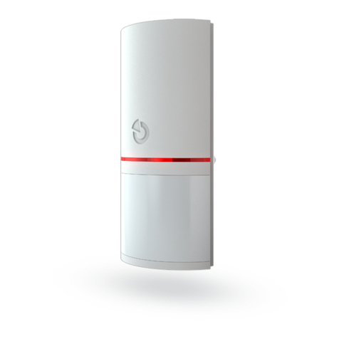
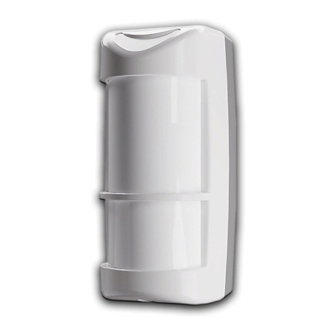
JA-60V Wireless outdoor PIR detector 1MEB 52101
JA-60V Wireless outdoor P.I.R. motion detector
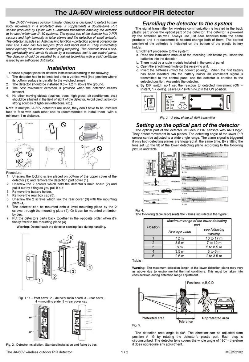
The JA-60V is an outdoor intruder detector designed to detect human
body movement in a protected area. Used PIR detector produced by Optex
has two double-layered detection patterns (upper and lower) both have to
be activated to trigger the alarm. This reduces false alarms, particularly
those caused by temperature changes, light reflection or small animals.
A tamper triggers an alarm if there is any attempt to tamper with the
detector.
The built-in transmitter is fully compatible with all JA-6X control panels.
Specifications
Power 3 V - 2 x AAA battery 1.5V
Battery life time about 1 year
Working frequency 433.92 MHz
RF Power
<
10 mV
Working range max. 100 m (open area)
Specification of the Optex VX 402R detector
Detection method Passive infrared
Coverage 12 m / 90° ; 14 segments
Mounting height 0.8 – 1.2 m
Detection speed 0.3 – 1.5 ms-1
Battery saving timer 5 or 120 seconds
LED indicator only in the test mode
Environmental class IV (EN 50131-1)
Operating temperature -20°C to +50°C
Waterproof IP54
Humidity 95%
Dimension 198 x 80 x 108 mm
Security grade 2 (EN 50131-1)
Can be operated according to ERC/REC 70-03
Hereby, Jablotron Ltd., declares that this JA-60V is in
compliance with the essential requirements and other
relevant provisions of Directive 1999/5/EC.
Original of the conformity assessment can be found at the web page
www.jablotron.cz, section Technical support.
Contents of the set: detector JA-60V, pole mounting kit, screw kit, area
masking plates, 2 AAA batteries
Installation
Select the proper place for mounting the detector according to
following:
1. Install the detector perpendicular to the ground to make upper
detection area parallel to the ground
2. Installation height is 0.8 – 1.2 m
3. Mount the detector so that a majority of traffic flow is across the
detection pattern
4. Too much light such as strong sunlight directed exactly to the sensor
may cause unstable condition. It is highly recommended to avoid
such installation.
3.1.1. 3.
0.8
1.2m
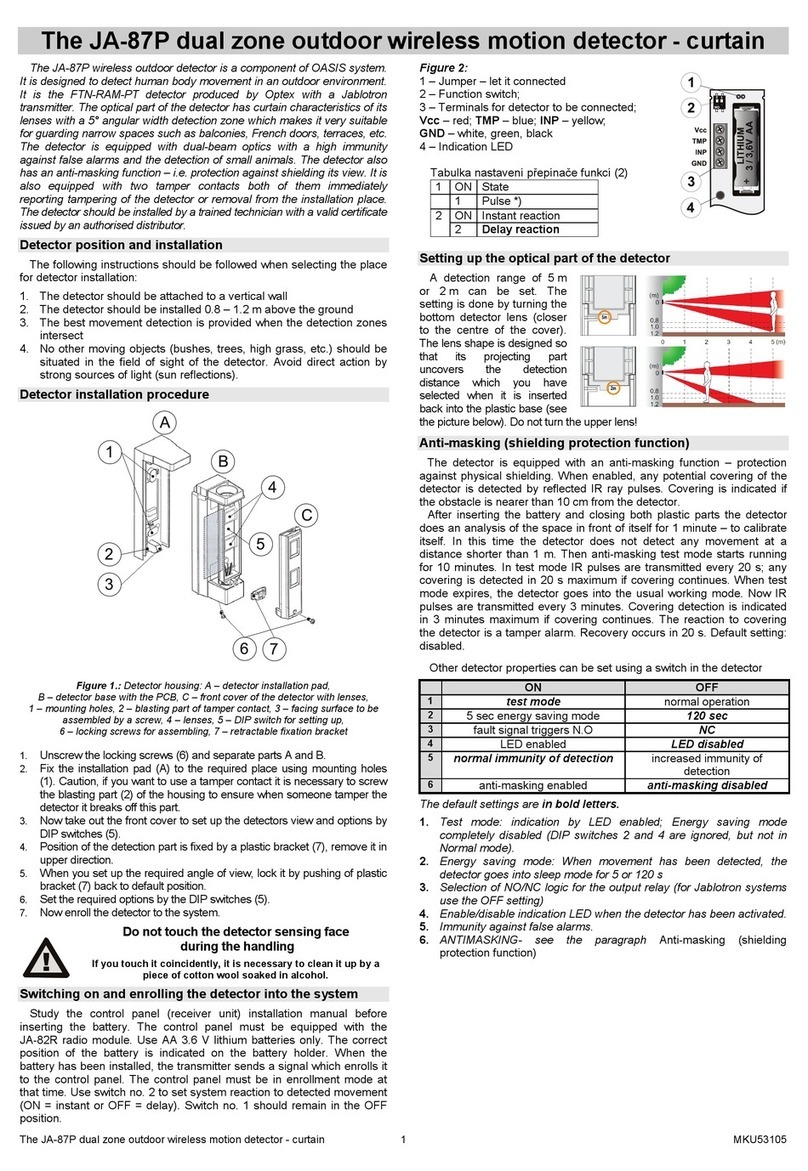
To open the detector:
1. Unscrew the lock screw and remove the top cover.
2. Unscrew the screws fastening the back box. Remove the back
box.
NOTE: never touch surface of the PIR sensor.
Fix the detector to desired place. Detector can be fixed directly on the
wall or by using supplied fix bracket on the pole (Ø 43 – 48 mm).
Optical Part
Cover
Lock Screw
Back Box
Pole Mounting
Bracket
Setting Switches
Enrollment of the detector to the receiver
The transmitter is placed below the optical part of the detector. Study
the installation manual of the receiver unit (control panel) first to learn how
enter the enrolling mode. When the receiver is switched to the enrolment
mode insert the two provided AAA batteries into the detector (polarity is
marked in the detector). The detector will generate an enrollment signal
after the batteries are installed.
INSTANT
DELAY
JA-60N transmitter
• Use DIP switch no. 1 to select the reaction of the system:
- instant (position ON)
- delay (position 1).
• Leave DIP switch no. 2 in position ON.
Adjustment
The upper detection area stays parallel to the ground. The lower area
moves as shown below depending on the position of the setting switch.
Detection length is therefore limited by the length of lower detection
area, since both upper and lower detection area have to be activated
at the same time to trigger the detector.
A
distance 0 - 12 m
D
distance 0 - 2 m
C
distance 0 - 5 m
B
distance 0 - 8 m
JA-60V Wireless outdoor PIR detector 2MEB 52101
Detection length setting table:
Max. detection length
Position Standard See Note bellow
A 12 m 10.0 to 15.0 m
B 8 m 6.0 to 10.0 m
C 5 m 4.0 to 5.5 m
D 2 m 1.5 to 2.5m
NOTE: the maximum detection length may vary as above due to
environmental thermal condition.
Detection Area
Level A,B,C,D
No Detection
Tolerance
Active area angle is 90°. By holding the pyro-electric unit it can be turned
in to desired direction ( in 15° steps).
45 90
45
Area masking – by provided masking plates section of the detection area,
which is exposed to the reflection of the sunlight, car light etc. can be
masked.
Sensitivity of the PIR sensor can be set by “SENS” switch in three
steps:
L - low
M - middle
H - high
Other parameters can be set using a DIP switch:
LED indicator OFF LED indicator ON
120 s 5 s Battery saving timer
4x 2x Pulse count
LED indicator is to be used for testing of the PIR detector. During
normal operation period is recommended to switch it off to save the
battery.
Depending on the 120s/5s battery saving timer DIP switch the movement
sensor will be blocked for a period of 5 or 120 seconds after a movement is
detected to conserves battery energy.
Depending on the Pulse count DIP switch the detector (both upper &
lower detection area) must be triggered 2 or 4 times to transmit the
alarm signal.
Operation test
Turn the LED indicator on, set the “battery saving timer” to 5 seconds
and close the detector. Every 5 seconds any movement in the
detection area will be indicated by the LED indicator and the alarm
information will be sent to the control panel.
Operation
To increase batteries lifetime it is highly recommended to switch the
“battery saving timer” to 120 seconds and switch off the LED indicator
in normal operating mode. The movement sensor will be blocked for 5 or
120 seconds after a movement is detected. This means that if there is
constant movement in the detection area the detector will transmit
information about the movement only once every 5 or 120 seconds.
Battery testing and replacement
The detector automatically checks the condition of its batteries. If it is
necessary to replace the batteries, the detector will inform the control panel
about it. If a low battery is indicated the detector works as normal but,
batteries should be replaced as soon as possible (within a week).
Before replacing the batteries, the control panel must be switched into
mode, which allows detectors opening (User mode or Programming
mode).
Use only high quality alkaline AAA batteries for replacement.
Note: Dispose of batteries safely depending on the type of the batteries and
local regulation. Although this product does not contain any harmful materials
we suggest you to return the product to the dealer or directly to the producer
after usage.
Troubleshooting
Problem Probable cause Remedy
Lower detection area is
unnecessarily long Set the detection area
properly
Detector receives
reflection of the reflector,
sunlight, car light etc.
Remove the reflector,
mask the area exposed to
the reflection of light or
change position of the
detector
There is a heat source in
the area that can cause
fast temperature change
(stove, heater etc.)
Remove the source of
heat or change position of
the detector
Detector
makes false
alarms
There is any moving object
in the area (laundry on the
clothesline, plans etc.)
Remove the moving object
or change position of the
detector
Detection area is not set
properly Set the detection are
properly
Occasionally
no detection Sensitivity is set to low (L) Change sensitivity to
medium (M) or high (H)
Low battery Replace the battery
LED does not light Turn LED switch ON
Detector
fails to work LED indicator lights but no
reaction on the control
panel
The control panel is out of
range, check the battery,
try to replace detector or
control panel
80
198
108
Dimensions
Note: Although this product does not contain any harmful
materials we suggest you to return the product to the dealer
or directly to the producer after usage.
Internet: www.jablotron.cz
Tel.: 483 559 999
fax: 483 559 993
Pod Ska lkou 3 3
466 01 Jablonec nad Nisou
123