manuals.online logo
Brands
  1. Home
  2. •
  3. Brands
  4. •
  5. jablotron
  6. •
  7. Security System
  8. •
  9. jablotron JA-110A II User manual

jablotron JA-110A II User manual

JABLOTRON ALARMS a.s.
Pod Skalkou 4567/33 46601 Jablonec n. Nisou
Czech Republic www.jablotron.com
||
|
JA-110A II Bus internal siren with battery back-up
JA-110A II Bus internal siren with battery back-up 1 / 2 MLP58600
The JA-110A II siren is a component of the JABLOTRON 100+
system. It is used for alarm indication inside a building with
the possibility to distinguish between types of alarm with different types
of indications. It can also be used for other acoustic indications (PG
outputs, entry/exit delays, a doorbell). Pressing a button on the siren
can silence the alarm indication in progress (which can also confirm
somebody’s presence on the premises or trigger a panic alarm (optional
function). The siren takes one position in the system and should
be installed by a trained technician with a valid certificate issued
by an authorized distributor.
Installation
The siren can be installed directly on a plaster wall or into a special
enclosure. The siren contains front and rear tamper contacts.
If you plan to connect the siren to a cable longer than 100 m,
we recommend using the BAT-3V2-CR2 back up battery (not included)
which is able to level loss of voltage. This way the siren can sustain
the alarm sound level stated in the technical specifications.
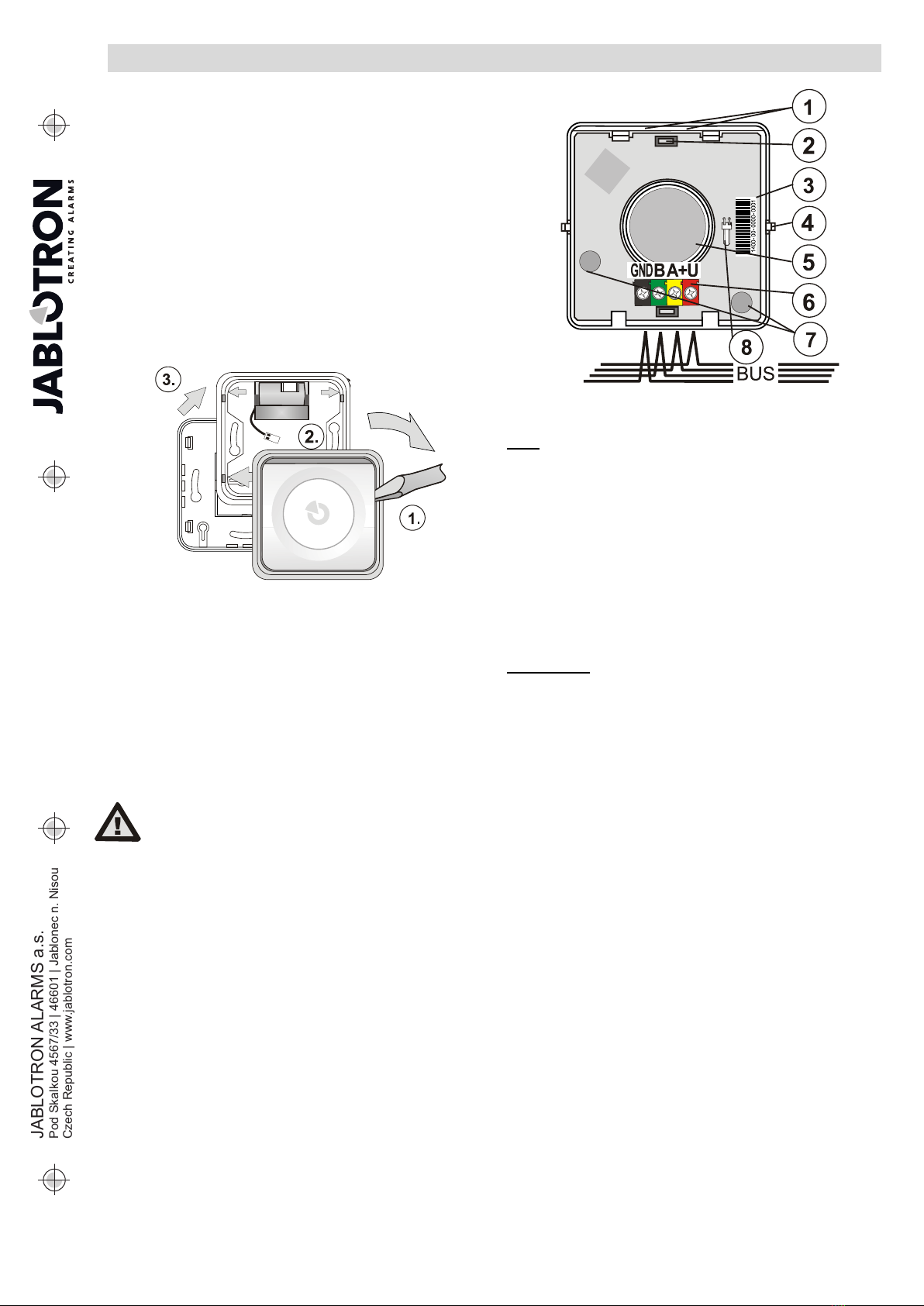
Figure 1: Disassembly of the siren before installation
1. Remove the body (buttons) of the siren from the plastic frame
by pressing on a side of the body (1.) using a screwdriver as shown
in figure 1.
2. Remove the middle part of the frame (3.) by pushing the 4 tabs
indicated by arrows (2.)
3. Push the BUS cable through a designated rectangular recess
in the plastic base.
4. Attach the plastic base to the selected place using screws.
If the siren uses a battery, place it underneath the top side
of the plastic base as shown in figure 1.
5. Assemble the plastic frame with the plastic base which will fix
the battery in position.
6. Connect the BUS cable to the terminals (6.) as shown in the figure
2. When using a battery, connect it to the battery connector (8.).
7. Insert the body (buttons) the plastic frame. Attention, the tamper
sensors (7) must be positioned above the magnets in the plastic
base.
8. Proceed by following the control panel installation manual. Basic
instructions:
a. When the power supply is connected, the yellow LED (1) starts
flashing to indicate the siren has not yet been enrolled into
the system.
b. Open the F-Link software, select an unused position
in the Devices tab and click on the Enrol button to launch
the enrolment mode.
c. Click on Scan/add new BUS devices, select the JA-110A II
siren from the list and double-click on it to confirm your
selection. The yellow LED light (1.) switches off.
Figure 2: 1 – LED indicators; 2 – buttons; 3 – production number;
4 - button tabs; 5 - piezo-electric siren; 6 – BUS terminal; 7 – tamper sensors
8 – battery connector for BAT-3V2-CR2
Notes:
−The enrolment of the siren to the control panel is also possible
by pressing a button (top or bottom). The siren enrols to the system
and the yellow LED switches off.
−Another option is entering the production code via the F-Link
software. The production code is on a sticker with a bar code which
is glued onto the rear side of the siren. All digits of the production
number are required (example: 1400-00-0000-0001).
−If you want to remove the siren from the system, erase it from
its position in the F-Link software.
Setting properties
Open the F-Link software, go to the Devices tab. Click on the
Internal settings button at the siren’s position to open a dialog window
where you can set the following options: (* indicates default settings).
The Setting tab:
Acoustic indication of an intrusion alarm from sections: The selection
of sections which should indicate an intrusion alarm via the siren. The default
setting is the indication of an intrusion from all sections.
Reaction: Determines whether the siren should indicate IW* (internal
warning) or EW (external warning) signals. Alarm indication with this siren
can also be completely disabled (other functions remain active).
Siren sound: Intermittent*, Continuous
Maximum siren time: 1, 2, 3*, 4, 5 minutes and OFF – if the OFF option
is selected then the acoustic indication corresponds with the Alarm length
parameter in the F-Link Parameters tab.
Different fire alarm indication: YES/NO* - Determines whether the siren
will differentiate between acoustic indications of fire and standard alarms.
The indication of an acoustic fire alarm is identical to smoke detectors with
internal sirens – fast beeping.
Other acoustic indication from sections: Selection determines which
sections will indicate other types of alarm via the detector. Indication for
all sections is enabled by default.
When controlled by a section: YES / NO* - If enabled, the siren
beeps 1x after setting, 2x after unsetting and 3x times when unsetting
after an alarm. It only does so for selected sections.
During warning: YES / NO* - when enabled, the siren reacts with
three beeps to the inability to set the system, unsuccessful setting and
unsetting with an active alarm memory.
Entry delay: YES / NO* - if enabled, the siren indicates the entrance
delays of the selected sections.
Exit delay when partially set: YES / NO* if enabled, the siren
indicates the exit delays of the selected sections when the system is set
partially. This option is available only when the entrance delay of fully
set sections is enabled.
Exit delay when fully set: YES / NO* if enabled, the siren indicates
the exit delays of the fully set selected section.
Level of volume of supplementary acoustic indication: Standard*,
Increased, By button, Programmable – Applies only to other acoustic
indication and the acoustic indication of PG outputs. It has no influence
on the volume of alarm indication. If the “By button” option is selected,
the volume can be changed by a user by pressing the lower part
of the siren for 3 seconds (when the system is out of Service mode) –
the change of volume is confirmed by a beep and in the volume
of the new selected volume.
Connect the siren to the BUS only
when the
control panel’s power supply
is completely disconnected.
JA-110A II Bus internal siren with battery back-up
JA-110A II Bus internal siren with battery back-up 2 / 2 MLP58600
The “Programmable” option displays time sliders which set a period
of time to switch between the standard and increased loudness during
the day.
The Signalling PG tab:
LED indicates sounding PG output: If enabled, acoustic indication
is triggered by an active PG output is continuously indicated by LED.
Sound indication can be set for each PG output:
Slow beeping - beeps 1x per second (as long as the PG output
is active).
Quick beeping – beeps 2x per second (as long as the PG output
is active).
1x ON/2x OFF – beeps 1x when the PG is activated, beeps 2x when
the PG is deactivated.
20 sec of beeping – beeps continuously for 20 secs when a PG
output is activated.
Melodies 1 to 4 – available doorbell melodies
System reaction to pressing
a siren button
By default, pressing the siren button during an alarm mutes the siren
and concurrently confirms a person’s presence in the building
(the control panel sends a report). It is possible to change the siren
button settings in the Devices window of the F-Link software to trigger
a different reaction, for example a Panic alarm.
Settings in accordance with security
grade 2
If security grade 2 is required, it can be configured by selecting
EN 50131, grade. 2. from System profiles located in the Parameters
tab in the F-Link software. The device will be configured according
to the selected standard.
Siren indication priority
Fire alarm indication has the highest priority followed by IW and EW
alarm.
A lower indication priority belongs to interaction with the system
(setting/unsetting…) followed by indication upon activation of PG
outputs (PG1 has a higher priority than PG2 etc.). Indication with
a higher priority always terminates indication with a lower priority.
Priority levels of acoustic indication in descending order: Fire alarm,
IW/EW alarm, warning indication, unsetting the system with an active
alarm memory indication, Setting/Unsetting, Entrance/Exit delay, alarm
memory indication, PG output indication and finally, the siren flashes
an LED light when the status of the tamper sensor changes.
Adding a battery to the siren
A battery is not factory-fitted in (the backup battery is optional).
By default, the siren is supplied by a control panel BUS. The siren can
be fitted with the BAT-3V2-CR2 battery for these two reasons:
The first reason may be using a cable longer than 100 m which may
lead to a low sound level due to loss of voltage. The battery prevents
such loss. The second reason may be using it as a backup solution
when the BUS power supply fails.
Connect the battery to the connector (8), the siren automatically
detects it and performs diagnostics. The measured values are then
displayed in the F-Link software.
The siren monitors its own battery status and informs a user
(alternatively the service technician) when the battery is close
to being depleted. The device continues in its function however
it is recommended to replace the battery within 2 weeks.
Use the BAT-3V2-CR2 type of battery specifically.
The battery should be replaced by a service technician while
the control panel is in Service mode. Do not discard the battery
in the trash; dispose of it at a waste collection point.
Note:
−If it is desired to operate the siren again without the battery, you
must first disconnect it from the BUS, disconnect the battery, wait
for 10 seconds and then reconnect the siren without the battery to
the BUS. There will be a new initialization when the siren evaluates
the operation without the battery.
Dimensions
Technical specifications
Power supply 12 V DC (9…15 V), from the BUS
Optional back up battery BAT-3V2-CR2(400mAh)
Current consumption in standby mode (quiescent) 5 mA
Current consumption for cable choice (maximal) 120 mA
Type of warning device type Z/12hr back-up
Siren piezo-electric, 100 dB/m (±5 dB/m)
Dimensions 80 x 80 x 35 mm
Weight (with battery) 92 g
Classification security grade 2/environmental class II
(according to EN 50131-1)
Environment Indoor general
Operating temperature range -10 °C to +40 °C
Average operating humidity 75 % RH, without condensation
Complies with EN 50131-1, EN 50131-4, EN 50130-4, EN 55032,
EN 62368-1, EN 50581
Certification body Trezor Test s.r.o. (no. 3025)
JABLOTRON ALARMS a.s. hereby declares that the JA-110A
II is in a compliance with the relevant European Union
harmonisation legislation: Directives No: 2014/35/EU,
2014/30/EU,
2011/65/EU. The original of the conformity
assessment can be found at www.jablotron.com –
The Downloads Section.
Note:
Although this product does not contain any harmful
materials we suggest you return the product to the dealer
or directly to the producer after use.

Other jablotron Security System manuals

jablotron OS-360A User manual

jablotron

jablotron OS-360A User manual

jablotron 100+ User manual

jablotron

jablotron 100+ User manual

jablotron JA-60 "Comfort" User manual

jablotron

jablotron JA-60 "Comfort" User manual

jablotron JA-162A User manual

jablotron

jablotron JA-162A User manual

jablotron JA-63 PROFI" User manual

jablotron

jablotron JA-63 PROFI" User manual

jablotron UC-261 User manual

jablotron

jablotron UC-261 User manual

jablotron JA-63 PROFI" User manual

jablotron

jablotron JA-63 PROFI" User manual

jablotron JA-63 PROFI" User manual

jablotron

jablotron JA-63 PROFI" User manual

jablotron GT 970 User manual

jablotron

jablotron GT 970 User manual

jablotron Mercury User manual

jablotron

jablotron Mercury User manual

jablotron CA-2103 Athos User manual

jablotron

jablotron CA-2103 Athos User manual

jablotron OS-360A User manual

jablotron

jablotron OS-360A User manual

jablotron JA-151IR User manual

jablotron

jablotron JA-151IR User manual

jablotron JA-60N User manual

jablotron

jablotron JA-60N User manual

jablotron JA-11A User manual

jablotron

jablotron JA-11A User manual

jablotron JA-162A User manual

jablotron

jablotron JA-162A User manual

jablotron JA-151A RB Operating manual

jablotron

jablotron JA-151A RB Operating manual

jablotron JA-162A User manual

jablotron

jablotron JA-162A User manual

jablotron JA-84P User manual

jablotron

jablotron JA-84P User manual

jablotron JA-163A User manual

jablotron

jablotron JA-163A User manual

jablotron Oasis User manual

jablotron

jablotron Oasis User manual

jablotron JA-163A Series User manual

jablotron

jablotron JA-163A Series User manual

jablotron 100+ User manual

jablotron

jablotron 100+ User manual

jablotron Azor User manual

jablotron

jablotron Azor User manual

Popular Security System manuals by other brands

Roger DIAL 1602M Operation and installation instructions

Roger

Roger DIAL 1602M Operation and installation instructions

Leisure Technologies WiTi Operations & installation guide

Leisure Technologies

Leisure Technologies WiTi Operations & installation guide

Pyle PLCM34WIR manual

Pyle

Pyle PLCM34WIR manual

Uniden UDW20553 Manual Del Usuario

Uniden

Uniden UDW20553 Manual Del Usuario

Honeywell Home TUXEDOW Quick installation guide

Honeywell Home

Honeywell Home TUXEDOW Quick installation guide

DSC PG4975 Bulletin

DSC

DSC PG4975 Bulletin

First Alert CO615 user manual

First Alert

First Alert CO615 user manual

Cisco MERAKI GX50 installation guide

Cisco MERAKI

Cisco MERAKI GX50 installation guide

Tyco Security Products DSC Power Series installation guide

Tyco Security Products

Tyco Security Products DSC Power Series installation guide

Vacron MDE52 user manual

Vacron

Vacron MDE52 user manual

PECO II NETMACS II manual

PECO II

PECO II NETMACS II manual

Edaphic Scientific ESRAD-200 operating instructions

Edaphic Scientific

Edaphic Scientific ESRAD-200 operating instructions

Bewator Bewacard BC615 quick guide

Bewator

Bewator Bewacard BC615 quick guide

Lorex SHS-2S instruction manual

Lorex

Lorex SHS-2S instruction manual

GE 60-960-95 installation instructions

GE

GE 60-960-95 installation instructions

API 1005 G quick start guide

API

API 1005 G quick start guide

urmet domus 1092 instructions

urmet domus

urmet domus 1092 instructions

Comax A112 Installation

Comax

Comax A112 Installation

manuals.online logo
manuals.online logoBrands
  • About & Mission
  • Contact us
  • Privacy Policy
  • Terms and Conditions

Copyright 2025 Manuals.Online. All Rights Reserved.