manuals.online logo
Brands
  1. Home
  2. •
  3. Brands
  4. •
  5. jablotron
  6. •
  7. Security System
  8. •
  9. jablotron OS-360A User manual

jablotron OS-360A User manual

OS-360A / OS-365A outdoor siren 1 / 2 MGZ52200
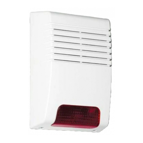
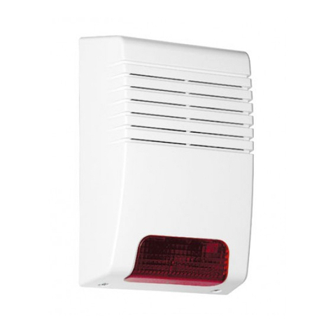
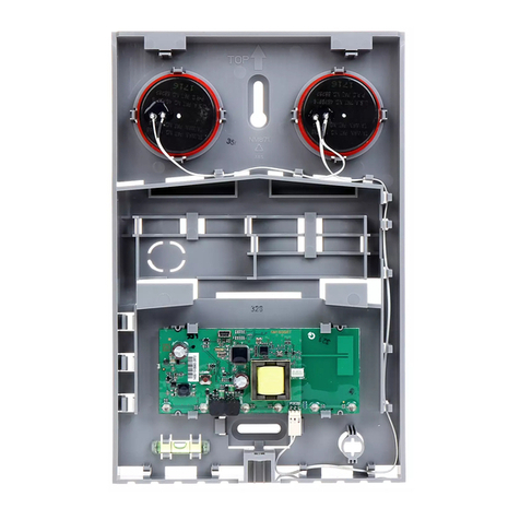
The OS-360A / OS-365A outdoor siren
The OS-360A / OS-365A is an outdoor siren with a rechargeable
backup battery.
Model OS-360A is equipped with a piezo-electric siren mainly
suitable for urban areas with a high building density. If necessary
another piezo-electric siren (ACM-OS360) can be used.
Model OS-365A is equipped with a compressive magneto-
dynamic horn siren mainly suitable for family houses or for buildings
with more space around them.
Two tamper sensors are built into the unit. They react to removing
the cover from the unit or tearing the siren off its position. The siren’s
housing is made of mechanically, weather and UV-resistant plastic.
The circuit board is protected against air humidity by a layer of special
varnish.
The built-in flashing light can be operated separately.
Installation
The siren should be fixed to a place which is not easily accessible,
but which allows for free sound transmission and, preferably, which is
also protected against direct rain. It is recommended to position the
siren in visible places to discourage criminals. It is also an advantage if
the flashing light can be seen from a distance to help the police or
security guards with locating the active siren.
Avoid installation near eaves where ice could form in winter.
• Remove the plastic cover by unscrewing the two screws under
plastic caps (the cover remains hanging on a cord).
• Fix the siren’s rear part onto the desired place.
• Route the cable into the siren through a suitable hole in the rear
part and tighten the fixing screws.
• Connect the cable to the PCB terminals, first removing the PCBs
protective plastic cover by unscrewing its fixing screw.
• Push the cable under the plastic tabs left of the PCB.
• Connect the back-up battery on the PCB, check that the sounder is
connected too and replace the PCB cover.
• Put the siren unit’s plastic cover back on and tighten the screws.
• Insert the plastic caps onto the screws
• Connect the power supply wires from the control panel to the siren
and perform a function test.
Please keep in mind the high acoustic power of the siren and
protect your hearing during testing.
Terminals
+12V – supply voltage (10 to 15 V DC)
GND – common ground
Power supply voltage drops cause the siren to sound (for 5 minutes
maximum) and the flashing light to flash (for a period of 30 minutes).
SIR – siren activation (the flasher is not affected)
FLA – flashing light activation (the siren is not affected)
The SIR and FLA input terminals react to a connection/disconnection
to/from GND according to the NO/NC setting of the jumper located on
the siren circuit board (NO = react to a connection, NC = react to a
disconnection).
ARM – a terminal for additional features
TMP, TMP – NC tamper switch output
Removing the siren cover or tearing the siren off its position causes
the tamper switches to disconnect. The tamper sensors are connected
in series with a 68R resistor which provides magnetic contact
protection against faulty wiring.
There are also NiCd backup battery and siren connectors on the
board. The NiCd backup battery comes from the factory
disconnected. Only connect it during installation.
The ARM, FLA and SIR terminals can also be used for backup
battery instantaneous voltage measurement. (e.g. during security
system checking). You can perform the measurement remotely without
any direct access to the siren. A voltage parameter is measured using
a voltmeter on the corresponding wire (see Table 1) when the wire is
disconnected from GND and the NC/NO jumper is set to ON.
ARM
disconnected voltage during battery charging
FLA
disconnected voltage during flashing (battery load approx. 100mA)
SIR
disconnected voltage during siren sounding (battery load. approx. 1A)
Table 1
OK
NC/NO
FLASH
Terminals Siren ( connectorsounder)
LED flash light
Cover tamper
Rear tamper
NiCd battery connection
Setting jumpers
Fig. 1 : Electronic circuit board front scheme
Setting jumpers
The three jumpers allow for the following settings:
ON the siren flashes 1x in 45 sec (ready state
indication)
OK OFF no ready state indication
ON SIR and FLA inputs react to a disconnection
from GND
NC/NO OFF SIR and FLA inputs react to a connection to
GND
ON flash for 30 minutes after a deactivation of the
siren
FLASH OFF stop flashing immediately after a deactivation
of the siren
Table 2
You can take the circuit board out of the housing to get easier access
to the jumpers.
Finishing installation, siren operation
Three seconds after being powered up (via the 12V terminal) the
siren briefly flashes to indicate readiness for testing. Perform siren
operation tests as described below to check if siren reactions
correspond to the jumper setting.
Warning: If the SIR and FLA input terminals are in an activated
state (according to the settings), then when the power is
connected up the siren will start the sound / light after 3 sec.
Siren operation:
Power supply disconnection. A disconnection from the mains supply
activates the siren – the siren starts to sound and flash. Restoring the
power supply silences the siren with a 3 sec delay. If the power supply
is permanently disconnected, then the siren sounding is stopped in 5
minutes. The flashing always continues for 30 minutes from the last
power supply disconnection.
SIR activation. The siren starts to sound for 5 minutes without flash
indication. A deactivation of the SIR input silences the siren
immediately.
FLA activation. The flashing light starts to flash. Depending on the
FLASH jumper setting, flash indication is terminated either immediately
or 30 minutes after a deactivation of the siren.
ARM state change. Connecting ARM to GND causes the siren to
indicate arming (setting): 1 flash plus 1 short beep. Disconnecting
ARM from GND causes the siren to indicate disarming (unsetting): 1
flash plus 2 short beeps.
Ready state. Normal operation is indicated by the siren flashing once
in every 45 seconds. This means that SIR and FLA are deactivated,
there is a proper power supply and the backup battery is charged. This
indication can be enabled/disabled by setting the OK jumper ON/OFF.
OS-360A / OS-365A outdoor siren 2 / 2 MGZ52200
Control panel wiring examples
If wired according to figure 2, the siren sounds and flashes during the
whole period of control panel alarms. The siren also provides an
acoustic confirmation of system setting/unsetting. The flashing stops
simultaneously with the sound.
JA-80K
OS-365A
01
COM
02
NC
NO
EW-C
IW
PGX
PGY
GND
A
B
+U
1k
PGX
function programmed to
ABC/AB/anything set
OK
NC/NO
FLASH
Fig. 2 Connection to the JA-80K control panel
If wired according to figure 3, the siren sounds and flashes during the
whole period of control panel alarms, with the light continuing to flash
for 30 minutes after alarm deactivation. No confirmation of system
setting/unsetting is provided, only a ready-state indication (1x flash in
every 45 sec) which is independent of the system status.
JA-82K
01
02
COM
03
04
EW
IW
PGX
PGY
GND
A
B
+U
1k
PGX
function programmed to
ABC/AB/anything set
OS-365A
OK
NC/NO
FLASH
Fig. 3 Connection to the JA-82K(R,C) control panel
If wired according to figure 4, the siren sounds and flashes during the
whole period of control panel alarms, with the light continuing to flash
for 30 minutes after alarm deactivation. Both acoustic confirmation of
system setting/unsetting and ready-state indication are provided – 1x
flash in every 45 sec, independently of the system status.
JA-65K
TMP
TMP
PGX
PGY
C
NC
NO
GND
SIR
+U
2k2
OS-365A
OK
NC/NO
FLASH
Fig. 4 Connection to the JA-65K control panel
If wired according to figure 5, the siren sounds and flashes during
power supply faults, with the sound continuing for just 3 more seconds
from the moment the power supply is restored. The flashing continues
for 30 minutes. No confirmation of system setting/unsetting and no
ready-state indication is provided.
JA-63K
OS-365A
L1
L2
COM
L3
L4
NO
NC
C
SIR
PGX
PGY
+U
GND
OK
NC/NO
FLASH
Fig. 5 A simplified two-wired siren-connection
Maintenance
The siren does not need any special maintenance. The NiCd battery
lifetime is about 3 years, depending on the working conditions.
Specialized auto-recharge mode keeps the battery in optimum state. If
the power supply (+12V and GND) is disconnected for a significantly
long period of time, then also disconnect the battery. It is
recommended to perform siren battery checking within general security
system testing – you can check the battery remotely without any direct
access to the siren.
Note: Whenever you handle any of the terminals (e.g. 12V
disconnection) disconnect the battery to avoid siren activation.
Important: An activation of the siren with a disconnected sounder
(see Fig. 1) does not cause any damage to the electronic circuits.
Instead, a high voltage is produced on the sounder connector.
Specification
Power supply 10 to 15 V DC
Standby consumption < 50 mA / 12 V
Maximum load consumption < 800 mA /12 V
Backup battery NiCd pack 4.8 V / 1800 mAh
Lifetime approx. 3 years
Piezoelectric siren (OS-360) sound level 113 dB / 1 m
With second piezo-electric siren (ACM-OS360) 118 dB / 1 m
Electro-acoustic siren (OS-365) sound level 110 dB / 1 m
Siren timer max. 5 minutes
Flasher time alarm duration +15 minutes / 0
Resistance of the tamper loop < 70
Ω
Enclosure IP 34D
Security grade 2 EN 50131-1, CLC/TS 50131-4
Working environment class IV, outdoor general
Operational temperature -25 to +60°C
EMC EN 50130-4, EN 55022
Safety EN 60950-1
Dimensions 230 x 158 x 75 mm
Jablotron Ltd. hereby declares that the OS-360A/365A is in
compliance with the essential requirements and other
relevant provisions of Directives 2004/108/EC and
2006/95/EC. The original of the conformity assessment can
be found on the web site www.jablotron.com, Technical
Support section.
Note: The NiCd backup battery contains cadmium (Cd).
Dispose of batteries safely depending on battery type and
local regulations. Although this product does not contain any
harmful materials we suggest you return the product to the
dealer or directly to the manufacturer after use.

This manual suits for next models

1

Other jablotron Security System manuals

jablotron JA-162A User manual

jablotron

jablotron JA-162A User manual

jablotron JA-114E User manual

jablotron

jablotron JA-114E User manual

jablotron MAESTRO JA-65 User manual

jablotron

jablotron MAESTRO JA-65 User manual

jablotron CA-2103 Athos User manual

jablotron

jablotron CA-2103 Athos User manual

jablotron JA-162A-UK User manual

jablotron

jablotron JA-162A-UK User manual

jablotron JA-152A User manual

jablotron

jablotron JA-152A User manual

jablotron OS-360 User manual

jablotron

jablotron OS-360 User manual

jablotron JA-163A Series User manual

jablotron

jablotron JA-163A Series User manual

jablotron Azor User manual

jablotron

jablotron Azor User manual

jablotron Profi User manual

jablotron

jablotron Profi User manual

jablotron OS-310 FORTE User manual

jablotron

jablotron OS-310 FORTE User manual

jablotron OS-360A User manual

jablotron

jablotron OS-360A User manual

jablotron JA-151A RB Operating manual

jablotron

jablotron JA-151A RB Operating manual

jablotron JA-10 Series User manual

jablotron

jablotron JA-10 Series User manual

jablotron 100+ User manual

jablotron

jablotron 100+ User manual

jablotron JA-63 PROFI" User manual

jablotron

jablotron JA-63 PROFI" User manual

jablotron JA-110A II User manual

jablotron

jablotron JA-110A II User manual

jablotron MAESTRO JA-65 User manual

jablotron

jablotron MAESTRO JA-65 User manual

jablotron Azor User manual

jablotron

jablotron Azor User manual

jablotron GT 970 User manual

jablotron

jablotron GT 970 User manual

jablotron 100 User manual

jablotron

jablotron 100 User manual

jablotron JA-60IR User manual

jablotron

jablotron JA-60IR User manual

jablotron JA-60 "Comfort" User manual

jablotron

jablotron JA-60 "Comfort" User manual

jablotron JA60K User manual

jablotron

jablotron JA60K User manual

Popular Security System manuals by other brands

Sgooway ZC-GSM015 user manual

Sgooway

Sgooway ZC-GSM015 user manual

Topkodas GTalarm2 Application note

Topkodas

Topkodas GTalarm2 Application note

Lorex LW2201 Series Frequently asked questions

Lorex

Lorex LW2201 Series Frequently asked questions

LiveLife 4GX user manual

LiveLife

LiveLife 4GX user manual

INIM Electronics IS1030 manual

INIM Electronics

INIM Electronics IS1030 manual

Heath CA-1 Assembly and operation

Heath

Heath CA-1 Assembly and operation

SENSTAR Symphony 7.2 Series user guide

SENSTAR

SENSTAR Symphony 7.2 Series user guide

AJAX HomeSiren quick start guide

AJAX

AJAX HomeSiren quick start guide

logika Smart Door Guardian product manual

logika

logika Smart Door Guardian product manual

Olarm PRO IDS X Series installation guide

Olarm

Olarm PRO IDS X Series installation guide

SECOLink MAS-800 Short user manual

SECOLink

SECOLink MAS-800 Short user manual

Aico Ei3030 instruction manual

Aico

Aico Ei3030 instruction manual

Lynx LYNXR Installation and setup guide

Lynx

Lynx LYNXR Installation and setup guide

Pix Controller UndercoverEye instruction manual

Pix Controller

Pix Controller UndercoverEye instruction manual

Valet Digital instruction manual

Valet

Valet Digital instruction manual

INVENTIVE SYSTEMS BA-200 Technical manual

INVENTIVE SYSTEMS

INVENTIVE SYSTEMS BA-200 Technical manual

GE 13-949 installation instructions

GE

GE 13-949 installation instructions

Worx WA0865 Get started guide

Worx

Worx WA0865 Get started guide

manuals.online logo
manuals.online logoBrands
  • About & Mission
  • Contact us
  • Privacy Policy
  • Terms and Conditions

Copyright 2025 Manuals.Online. All Rights Reserved.