manuals.online logo
Brands
  1. Home
  2. •
  3. Brands
  4. •
  5. jablotron
  6. •
  7. Security System
  8. •
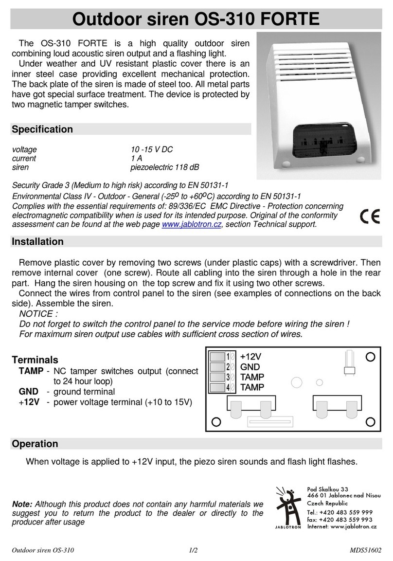
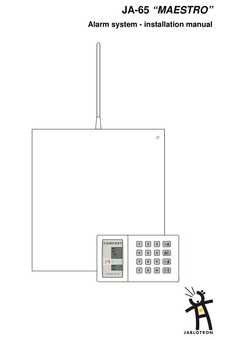
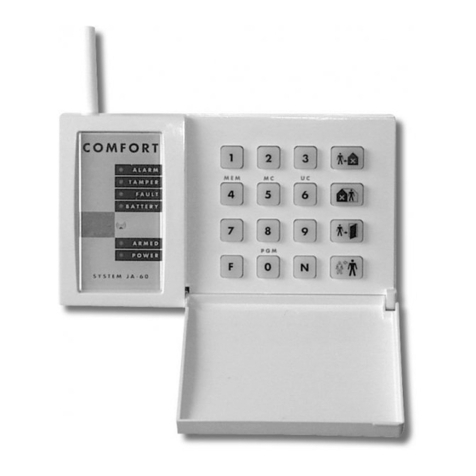
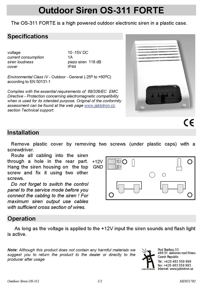
  9. jablotron JA-151IR User manual

jablotron JA-151IR User manual

JABLOTRON ALARMS a.s.
Pod Skalkou 4567/33 46601 Jablonec n. Nisou
Czech Republic www.jablotron.com
||
|
JA-151IR wireless 4beam optical barrier
JA-151IR wireless 4beam optical barrier 1 / 2 MMY51904
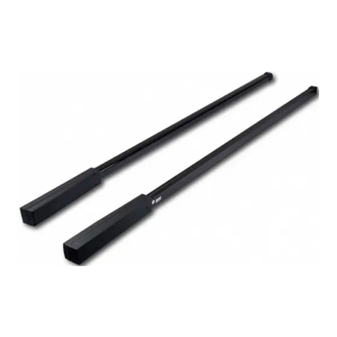
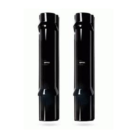
The JA-151IR four-beam infra-red optical barrier is designed for the indication
of a breach into a protected area by crossing the IR line between the transmitter
and the receiver. The barrier is a product SL-350QFR by Optex supplemented
with transmitters JA-150TX-V4 produced by JABLOTRON ALARMS compatible
with the JABLOTRON 100. The device is equipped with a 4-ray optical part with
a high immunity against false alarms and the detection of small animals.
The barrier occupies two positions in the system. The transmitters regularly
perform automatic tests and report their status to the system. The barrier should
be installed by a trained technician with a valid certificate issued by an authorised
distributor.
Barrier installation
The following instructions should be observed when selecting a place for
barrier installation:
 Both units must be installed on a stationary construction (e.g. a wall
or a thick post) at the same height and should face each other.
 The area between the barrier units must not be blocked by any bushes
or tall grass.
 There can be up to a 100 m distance between the units indoors.
(The distance could be reduced outdoors.)
 The receiver unit must not be affected by direct sunlight.
 The units should be installed 0.7 – 1 m above the ground.
 If the IR beam is parallel to a wall, there must be at least a 1 m distance
between the beam and the wall.
 If multiple barriers are used, it is necessary to avoid influencing the beam
of one barrier by another barrier
Fig. 1: Undesirable locations
Installation steps:
The transmitting unit (marked TRANSMITTER) and the receiving unit
(marked RECEIVER) are of identical mechanical construction.
Fig. 2 Barrier parts (identical for transmitter and receiver): A – Front barrier
cover, B – Main unit, C – Base of the unit, D – Rear cover, 1 – The locking
screw of the front cover, 2 – Viewfinder for barrier alignment, 3 – Optical
part, 4 – Setting of optical viewing angle, 5 – Screws for main unit fixing,
6 – Battery holders, 7 – Jablotron transmitter
1. Unscrew the front cover screw (1) and remove it. Use a coin inserted
between the thresholds of the plastic parts to get it out and carefully take
it off by a prying motion.
2. Take away the main unit with the base (B+C) by releasing the 4 screws
(5) in the corner of the base unit (C). Then take the base of the unit away
from the rear cover (D).
3. Install the rear cover (D) onto the selected place, either directly onto a
wall or a post. On the rear plastic case holes are pre-pressed for
installation on the wall (WALL) or for a pole (POLE).
4. The Jablotron transmitter (7) and battery holders (6) are placed inside
the rear cover (D). Everything is connected to the main unit by a coloured
wiring harness with connectors. The connectors are unmistakable.
Enrolling the barrier transmitters into the
system
The radio transmitters for communication with the JABLOTRON 100
system are placed inside the rear cover (D) underneath the optical part
of the detector. The barrier occupies 2 positions in the system.
Barrier activation is reported by the receiving part of the barrier. Both barrier
parts report tampering and battery status.
For powering each unit always use a minimum of two SAFT LSH20
lithium batteries (they are not included in the package). The correct
position of the batteries is marked inside the holder. Mind the correct
polarity during insertion. Four batteries can be inserted into the receiver and
transmitter as well. This prolongs the barrier operational time.
1. Enrol the radio transmitter to the system.
a. There must be a JA-11xR radio module installed in the system.
b. Go to the F-Link software, select the required position in the
Devices window and launch the enrolment mode by clicking on the
Enrol option.
c. Insert the batteries (mind the correct polarity). The enrolment signal
is transmitted when the first battery is inserted into the detector
and the device is enrolled to the selected position.
2. Screw on the base (C) and main (B) unit.
3. Do the barrier optical alignment according to the following chapter.
4. Screw on the cover and test the barrier functioning.
Receiver
N.C. N.O.
Status (INP) Pulse (INP)
AUX Fault AUX Antimasking
Not used
Transmitter
N.C. N.O.
Status (INP) Pulse (INP)
AUX Fault AUX Antimasking
Not used
Factory settings highlighted by bold letters.
Fig. 3 Radio transmitter JA-150TX-V4 (matched transmitter and receiver):
1 – terminals, 2 – option DIP switch (factory pre-set), 3 – external tamper
connector, 4 – external antenna jumper, 5 – external antenna connector
If needed the transmitter can be equipped with an AN-868 (2PIN)
external antenna connected to the connector (5) and disconnect
the jumper (4).
Setting up the optical part of the barrier
Always perform the detector settings and beam alignment when
the tamper contact is blocked. The optical part of the barrier must
be adjusted so that the optical parts facing each other are physically
aligned. Both units are equipped with adjusting elements for the adjustment
of direction and a view-finder for precise adjustment. The unit opposite
the one you want to adjust must be in the centre of the aiming cross and
the cross must be in the centre of the view-finder (see fig. 4). There are
optical covers placed inside the front barrier covers. Slide the cover on the
lower optical part and perform the upper optical part setting then repeat the
procedure for the lower part of the optics. If it is needed to test the barrier
function with a closed front cover it is possible to lock the tamper contact by
a rotating plate to avoid physical closing of the barrier. The rotating plate
is placed next to the tamper contact.
Fig. 4: Setting up the optical part
1234
ON
1234
ON
JA-151IR wireless 4beam optical barrier
JA-151IR wireless 4beam optical barrier 2 / 2 MMY51904
When the setting is complete, it is followed by adjustment of the receiver
unit:
Fig. 5: Setting up using a multimeter
A permanently lit LED on the transmitter/receiver indicates that the beam
has been interrupted (or wrongly adjusted). The better the beam reception,
the longer the break between the LED flashes – see fig. 8, LED 2.
When the LED stops flashing, continue looking for the ideal position indicated
by the highest voltage measured on the voltmeter (see fig. 5). The ideal
measured value should be higher than 2.4 V.
Setting up the electronic part of the barrier
Both units are equipped with settings switches. Each barrier has specific
beam modulation so that´s why several barriers can be installed near each
other. The barriers cannot influence each other.
There is a DIP switch on the receiving unit with six switches. It is possible
to set the beam modulation (the setting has to be the same on the receiver
as on its partner transmitter). For beam modulation setting see figure 6.
For examples of installations, see the original manual in the delivery pack.
It is possible to set a 2 minute sleep time after an alarm (beam interruption)
in order to save the batteries. The setting is done by switching switch no. 3
to the ON position. The auxiliary output is set by DIP no. 4. Don´t change
this setting, it ensures the correct triggering of the fault status. DIP switches
no. 5 and no. 6 determine the reaction sensitivity. See options for settings
in fig. 7.
Note: If the beam strength is reduced (less than 50%) for more than 20 s,
it triggers a fault and a report is sent to the control panel.
Fig. 6: Beam modulation setting
Fig. 7: Reaction time setting
Testing
Perform the barrier test in three places (A, B and C – next to both the
units and in the centre). The setting is completed only if the barrier reacts
successfully in all three positions. You should also check the signal
transmission to the system control panel. Only then is it possible to put back
the unit covers and secure them and then perform the final test.
Fig. 8: Barrier function test
The indication LEDs on the units (fig. 8) have the following functions
when the tamper is unlocked:
Alarm (1) indicator lights when the beam is interrupted.
Level indicator (2), the better the beam reception, the longer the break
between the LED flashes.
Low Battery (3) indicators flash if the batteries in the unit are discharged.
Always replace both (all) batteries at the same time. (SAFT LSH20 lithium
batteries).
Power (4) indicator- lights when the transmitter unit works.
A B
1
2
3
4
3
Fig. 9: Indication LEDs in units: A – Receiver,
B – Transmitter, 1 – Alarm, 2 – Beam quality Level–indicator,
3 – Low Battery indicator, 4 –Transmitter operation indication (Power)
Replacing the batteries
The detector checks the battery status automatically. Nearly drained
battery is reported by continuous flashing of yellow signalling LED
on the detector (1 flash per sec) and at the same time low battery status
is reported to the control panel. The detector remains fully functional.
The battery should be changed as soon as possible.
The control panel must be in service mode before battery changing
(see the control panel installation manual). Tamper contact must be
pressed several times after opening the cover and removing the battery to
discharge capacitors. We recommend to use lithium batteries SAFT LSH20
(3.6 V 13 Ah). Always replace all batteries simultaneously. If it is needed
to increase the lifetime of the batteries you can add two more batteries.
Then you have 4 batteries in one unit.
Technical specifications
Power 4x (8x) LSH20 type lithium batteries (3.6 V/13 Ah)
Please note: Batteries are not included
Current consumption (nominal/maximal) 765 μA/50 mA
Average battery lifetime approx. 3 years* (6 years)*
* with 120 s energy saving mode
Communication band 868.1 MHz, JA-100 protocol
RF range up to 300 m (open area)
Optex barrier parameters
Distance between barrier units max. 100 m
Barrier installation height 0.7 – 1.0 m
Object motion speed as set by an installer
Enclosure protection IP65
Max. relative humidity of the environment 95 %
Weight (receiver + transmitter) 3300 g
Operational environment according to EN 50131-1 IV
Operational temperature range -20 °C to +60 °C
Security grade according to OPTEX
Complies with ETSI EN 300220, EN 50130-4,
EN 55022, EN 60950-1
Can be operated according to ERC REC 70-03
JABLOTRON ALARMS a.s. hereby declares that the JA-151IR composed
of Optex detector SL-350QFR and radio module JA-150TX-V4 is in
a compliance with the relevant Union harmonisation legislation:
Directives No: 2014/53/EU, 2014/35/EU, 2014/30/EU, 2011/65/EU.
The original of the conformity assessment can be found at
www.jablotron.com - Technical Support section.
Note: Although this product does not contain any harmful materials
we suggest you return the product to the dealer or directly to the producer
after use. For more detailed information visit www.jablotron.com.
138
83
452
83,5
222
390
265
Obr. 10: Dimensions of units

Other jablotron Security System manuals

jablotron 100+ User manual

jablotron

jablotron 100+ User manual

jablotron JK-82UK Oasis User manual

jablotron

jablotron JK-82UK Oasis User manual

jablotron JA-60IR User manual

jablotron

jablotron JA-60IR User manual

jablotron GT 970 User manual

jablotron

jablotron GT 970 User manual

jablotron JA-11A User manual

jablotron

jablotron JA-11A User manual

jablotron Azor User manual

jablotron

jablotron Azor User manual

jablotron JA-60 "Comfort" User manual

jablotron

jablotron JA-60 "Comfort" User manual

jablotron JA-150A II User manual

jablotron

jablotron JA-150A II User manual

jablotron JA-63 PROFI" User manual

jablotron

jablotron JA-63 PROFI" User manual

jablotron JA-60N User manual

jablotron

jablotron JA-60N User manual

jablotron MAESTRO JA-65 User manual

jablotron

jablotron MAESTRO JA-65 User manual

jablotron JA-162A User manual

jablotron

jablotron JA-162A User manual

jablotron UC-261 User manual

jablotron

jablotron UC-261 User manual

jablotron JA-16A RB User manual

jablotron

jablotron JA-16A RB User manual

jablotron JA-152A User manual

jablotron

jablotron JA-152A User manual

jablotron JA-110A II User manual

jablotron

jablotron JA-110A II User manual

jablotron 100 User manual

jablotron

jablotron 100 User manual

jablotron JA-151IR User manual

jablotron

jablotron JA-151IR User manual

jablotron JA60K User manual

jablotron

jablotron JA60K User manual

jablotron Oasis User manual

jablotron

jablotron Oasis User manual

jablotron JA-151A User manual

jablotron

jablotron JA-151A User manual

jablotron Oasis RC-87 User manual

jablotron

jablotron Oasis RC-87 User manual

jablotron OS-360A User manual

jablotron

jablotron OS-360A User manual

jablotron JA-163A Series User manual

jablotron

jablotron JA-163A Series User manual

Popular Security System manuals by other brands

Elk ELK-6040 Installation and setup guide

Elk

Elk ELK-6040 Installation and setup guide

Lorex SHS-2S7LD Series instruction manual

Lorex

Lorex SHS-2S7LD Series instruction manual

Rokonet WisDom user manual

Rokonet

Rokonet WisDom user manual

Agri Alert 9600 installation manual

Agri Alert

Agri Alert 9600 installation manual

STI Theft Stopper STI-6200 Series Install

STI

STI Theft Stopper STI-6200 Series Install

ST Engineering Electronics DigiSAFE DiskCrypt M10 user manual

ST Engineering Electronics

ST Engineering Electronics DigiSAFE DiskCrypt M10 user manual

ADEMCO LYNXR24 user guide

ADEMCO

ADEMCO LYNXR24 user guide

Kaba Saflok SAM RF Operation manual

Kaba

Kaba Saflok SAM RF Operation manual

0N3 X5 System user manual

0N3

0N3 X5 System user manual

Lorex SG17LD800 Frequently asked questions

Lorex

Lorex SG17LD800 Frequently asked questions

Nice HSCU1 Instructions and warnings for installation and use

Nice

Nice HSCU1 Instructions and warnings for installation and use

FireAngel CO-9X-10-EU user manual

FireAngel

FireAngel CO-9X-10-EU user manual

Honeywell ADEMCO VISTA-40 Installation and setup guide

Honeywell

Honeywell ADEMCO VISTA-40 Installation and setup guide

DA System Aplique 6/14COM installation guide

DA System

DA System Aplique 6/14COM installation guide

Carmanah R247-E user manual

Carmanah

Carmanah R247-E user manual

ADEMCO Ademco VISTA-40 user guide

ADEMCO

ADEMCO Ademco VISTA-40 user guide

Salto IQ2.0 installation guide

Salto

Salto IQ2.0 installation guide

LifeLink Prodigy LP2500 Operation manual

LifeLink

LifeLink Prodigy LP2500 Operation manual

manuals.online logo
manuals.online logoBrands
  • About & Mission
  • Contact us
  • Privacy Policy
  • Terms and Conditions

Copyright 2025 Manuals.Online. All Rights Reserved.