manuals.online logo
Brands
  1. Home
  2. •
  3. Brands
  4. •
  5. Jamara
  6. •
  7. Motorized Toy Car
  8. •
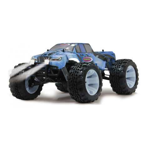
  9. Jamara Vulcano EP RTR 2,4 GHz User manual

Jamara Vulcano EP RTR 2,4 GHz User manual

Other manuals for Vulcano EP RTR 2,4 GHz

3

This manual suits for next models

3

Other Jamara Motorized Toy Car manuals

Jamara 404515 User manual

Jamara

Jamara 404515 User manual

Jamara Robot Spaceman User manual

Jamara

Jamara Robot Spaceman User manual

Jamara 410032 User manual

Jamara

Jamara 410032 User manual

Jamara 460447 User manual

Jamara

Jamara 460447 User manual

Jamara Ultra BL 8 2,4 GHz User manual

Jamara

Jamara Ultra BL 8 2,4 GHz User manual

Jamara 41 0011 User manual

Jamara

Jamara 41 0011 User manual

Jamara Ferrari F1 User manual

Jamara

Jamara Ferrari F1 User manual

Jamara Bugatti Chiron 2,4GHz User manual

Jamara

Jamara Bugatti Chiron 2,4GHz User manual

Jamara Vulcano EP RTR 2,4 GHz User manual

Jamara

Jamara Vulcano EP RTR 2,4 GHz User manual

Jamara 405002 User manual

Jamara

Jamara 405002 User manual

Jamara Mercedes-Benz G55 AMG 2,4GHz User manual

Jamara

Jamara Mercedes-Benz G55 AMG 2,4GHz User manual

Jamara Lamborghini Sián FKP 37 User manual

Jamara

Jamara Lamborghini Sián FKP 37 User manual

Jamara Ferrari 458 Italia 2,4GHz User manual

Jamara

Jamara Ferrari 458 Italia 2,4GHz User manual

Jamara Ice Tiger EP 2,4 GHz User manual

Jamara

Jamara Ice Tiger EP 2,4 GHz User manual

Jamara 405158 User manual

Jamara

Jamara 405158 User manual

Jamara Audi R8 LMS Performance 2,4GHz User manual

Jamara

Jamara Audi R8 LMS Performance 2,4GHz User manual

Jamara Ferrari 458 Italia User manual

Jamara

Jamara Ferrari 458 Italia User manual

Jamara BMW i8 User manual

Jamara

Jamara BMW i8 User manual

Jamara Ferrari 458 Speciale User manual

Jamara

Jamara Ferrari 458 Speciale User manual

Jamara McLaren P1 User manual

Jamara

Jamara McLaren P1 User manual

Jamara Strong Bull User manual

Jamara

Jamara Strong Bull User manual

Jamara 405093 User manual

Jamara

Jamara 405093 User manual

Jamara 402116 User manual

Jamara

Jamara 402116 User manual

Jamara Derago XP1 User manual

Jamara

Jamara Derago XP1 User manual

Popular Motorized Toy Car manuals by other brands

Reely Dune Fighter 3S operating instructions

Reely

Reely Dune Fighter 3S operating instructions

REVELL 1970 Chevelle SS 454 manual

REVELL

REVELL 1970 Chevelle SS 454 manual

Team Losi Micro Rally Car Operation guide

Team Losi

Team Losi Micro Rally Car Operation guide

Eduard Humber Scout Car Mk.I exterior quick start guide

Eduard

Eduard Humber Scout Car Mk.I exterior quick start guide

REVELL 68 CHEVY CHEVELLE SS 396 manual

REVELL

REVELL 68 CHEVY CHEVELLE SS 396 manual

Schumacher Pro Cat instruction manual

Schumacher

Schumacher Pro Cat instruction manual

Tamiya TT-01 TYPE E instruction manual

Tamiya

Tamiya TT-01 TYPE E instruction manual

Eduard Krupp Protze 6x4 1/48 quick start guide

Eduard

Eduard Krupp Protze 6x4 1/48 quick start guide

New Bright 61072UEP quick start guide

New Bright

New Bright 61072UEP quick start guide

Team Durango DEX410v5 manual

Team Durango

Team Durango DEX410v5 manual

PLAYMOBIL 9536 manual

PLAYMOBIL

PLAYMOBIL 9536 manual

Atomic BZ3 instruction manual

Atomic

Atomic BZ3 instruction manual

Aiyaplay 370-290V00 user manual

Aiyaplay

Aiyaplay 370-290V00 user manual

ZEROTRIBE Zetricks ZT1144 instruction manual

ZEROTRIBE

ZEROTRIBE Zetricks ZT1144 instruction manual

INJUSA 412 Assembly instructions

INJUSA

INJUSA 412 Assembly instructions

Maverick MSC-30BR-WP instruction manual

Maverick

Maverick MSC-30BR-WP instruction manual

Land of B. Rollin' Riders quick start guide

Land of B.

Land of B. Rollin' Riders quick start guide

TLR 22SCT 2.0 user manual

TLR

TLR 22SCT 2.0 user manual

manuals.online logo
manuals.online logoBrands
  • About & Mission
  • Contact us
  • Privacy Policy
  • Terms and Conditions

Copyright 2025 Manuals.Online. All Rights Reserved.

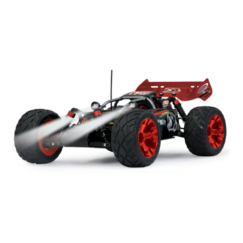
Vulcano EP
RTR 2,4 GHz
No. 053368 EP
No. 053369 EP LiPo
FR - Remarques générales
La société Jamara e. K. n’est pas responsable de dommages, que ce soit au niveau du modèle
ou causé par celui-ci, résultant d’une utilisation non appropriée. Seul le client est responsable
concernant la mise en oeuvre et l’utilisation conforme du matériel; cela va de l’assemblage, en
passant par la charge des accus et allant jusqu’au domaine d’utilisation. Pour cela, veillez lire
attentivement la notice d’assemblage et d’utilisation, celle-ci contient d’importantes informations
ainsi que les consignes de sécurités.
GB - General information
Jamara e.K. is not liable for any damage caused to the product itself or through this, provided this
is due to improper operation or handling errors. The Customer alone bears the full responsibility for
the proper use and handling, including without limitation, the assembly, the charging process, the
use and choice of the operation area. Please refer to the operating and user instructions, it contains
important information and warnings.
Déclaration de conformité
Par la présente, la société Jamara e.K. déclare que ce modèle „Vulcano EP RTR
2,4 GHz, No. 053368, No. 053369“ est conforme en tous points avec les textes de
la directive de l’union européenne sous les directives 1999/5/CE et 2011/65/EU. Vos
pourrez également trouver des informations sur notre site Internet:
www.jamara-shop.com/Conformite
Certicate of Conformity
JAMARA e.K. hereby declares that „Vulcano EP RTR 2,4 GHz, No. 053368, No. 053369“ follow the
regulations and requirements as well as any ther relivant directives of the EEC directive
2014/53/EU and 2011/65/EU.
Further information can also be found at: www.jamara-shop.com/Conformity
Ce modèle n’est pas un jouet !
N‘est pas adapté pour les personnes de moins de 14 ans.
Attention: Garder loin nécessairement enfants de moins de 36 mois.. DANGER
D‘ETOUFFEMENT! Contient de petites pièces facilement avalables.
This model is not a toy!
Not suitable for people under 14 year.
Warning: Not suitable for children under 36 months. RISK OF SUFFOCATION!
Contains small parts which can be swallowed. Keep away necessarily from children.
Attention!
Avant l’utilisation:
Allumez le modèle en premier puis votre radiocommande.
Après utilisation:
Arrêtez le modèle en premier puis votre radiocommande.
●N’utilisez jamais le modèle à une distance hors de votre visibilité. La visibilité maximale
ainsi que la ortée maximale dépendent de plusieurs facteurs tels que le temps, le lieu
d’utilisation et les présentes fréquences perturbatrices. Pour cela, avant chaque usage,
veuillez effectuer un test de visibilité et de portée avec une deuxième personne qui tient
le modèle xé et vériez les réactions du modèle en usage en cas de pertes de signal
due par exemple à des piles usées ou à un émetteur éteint.
Attention!
Before operating:
Switch the transmitter on rst then the model.
When nished:
First switch off the model then the transmitter.
● Never operate your model beyond sight. Both the maximum visibility as well as the max.
range of your model will depend on many factors such as weather, location and
interfering frequencies. Therefore, before each use perform a range test with a second
person securely holding the model and also check how the model reacts if there is a
signal failure e.g. when empty transmitter batteries are installed.
21/17
FR - Notice
GB - Instruction
Empfohlenes Werkzeug Recommended Tool
No. 19 0065
Appareil de mesure
d’inclinaison
Camber adjusting Tool
No. 19 0060
Cales de hauteur
Height lange
No. 23 2060
Ruban adhésif double face
Doublesided power tape
No. 23 2423 medium
Frein  let
Nut lock
No. 23 0461 400 ml
Mouse de nettoyage spécial
Special cleaning foam
No. 50 5401 klein/small
Clip  xation de carrosserie
Body clips
No. 19 3129
Banc de montage avec plateau
tournant
Car Stand
No. 19 7595
Werkzeug 12in1
Tool 12in1
No. 05 9273 1:10
Clip  xation de carrosserie
Body clips
No. 28 1787 Louise
Foret manuel pour gabarit et
couvercle
Body reamer with cap and sizes
No. 15 3060
X-Peak 50 BAL
Chargeur
Charger
No. 28 1730
Lexanschere
Lexan scissors
FR - Veuillez lire attentivement et entièrement la notice et les consignes de sécurités avant tout
utilisation de ce produit!
GB - Read the complete instructions and security instructions carefully before using the model.
No. 15 3055
X-Peak 80 BAL
Chargeur
Charger
No. 15 3058
X-Peak 80 BAL Pult
Chargeur
Charger
2
Adapteur/
Charging adapter
Chargeur/
Charger
Chargeur/Charger
Accu/Battery
Accu/Battery
Vers. 053368
Vers. 053369
Reglulateur
ESC
ON/OFF
Accu/Battery
FR - Premiers pas
Assurez-vous d’avoir toutes les pièces prévues dans le kit.
Emetteur, modèle, chargeur, accu de propulsion (en place).
Dans un premier temps il faut charger l’accu de propulsion.
Branchez le chargeur sur une prise secteur 230V. Connectez
celuici avec l’accu de propulsion.
Si le connecteur du chargeur et le connecteur de l’accu ne
devait pas corre- spondre vous avez un adaptateur à votre dis-
position dans le kit. La durée moyenne de charge de l’accu de
propulsion déchargé livré dans le kit est d’environ 6 - 8 heures.
Placez 4 piles type AA ou accus correspondants dans
l’émetteur. Si vous utilisez des accus pour alimenter l’émetteur
il faut tout d’abord les charger avec un accu acheté séparé-
ment.
Lisez attentivement le chapitre concernant votre radiocomman-
de et ses éléments de commandes.
Mettez en route l’émetteur et assurezvous que les trims soient
bien en position de neutre pour chaque fonction. Vous avez
acheté un modèle RTR. De ce fait votre voiture est préparée en
grandes lignes pour être utilisé de suite.
Néanmoins il est important de véri er avant et après chaque
utilisation qu’il n’y ait pas de dégâts mécaniques ou de prob-
lèmes électriques. De même il faut contrôler toutes les pièces
mobiles qu’elles soient libres de toutes contraintes, sans jeu et
que toutes les vis soient correctement serrées. Mettez
en place l’accu de pro dans son compartiment. Veillez à ce que
le support d’accu soit à nouveau bien  xé avec les deux goupil-
les et que l’accu de propulsion est bien  xé dans son support
sans grand jeu. Connectez l’accu de
propulsion avec le régulateur du modèle. Tenez la voiture en
l’air au cas où lemoteur démarrerait brutalement lors de la mise
en marche. Mettez en marche le régulateur avec le bouton On/
Off. Posez le modèle sur le sol et testez le bon fonctionnement
des différentes commandes. Directionnel gauche/droite,
vitesse avant/arrière. Si les roues ne devaient pas être droites
vers l’avant alors que le volant de l’émetteur est au centre il est
possible de réci er cette position à l’aide du trim sur l’émetteur.
Trim L/R = direction
Trim V/R = avant/arrière
Si les roues devaient tourner en avant ou en arrière alors que
vous n’avez pas touché à la commande des gaz, il faut com-
penser cette action en utilisant le trim de la fonction gaz jusqu’à
ce que les roues restent immobiles.
Nous vous conseillons maintenant d’activer la fonction Failsafe
de votre récepteur. Cette fonction est désactivée en sortie
d’usine. Vous pouvez activer la fonction Failsafe en laissant le
manche des gaz de l’émetteur en
position de neutre (voir chapitre Fail Safe) et en appuyant sur
la touche Failsafe de votre récepteur jusqu’à ce que la LED
clignote puis en relâchant la touche. N’activez cette fonction
qu’avec le manche des gaz en position de neutre pour une
voiture électrique a n que la fonction gaz du modèle,
en cas de perte de signal, se place automatiquement en
position ralentie dé nie au préalable.
Maintenant vous pouvez effectuer un circuit test avec votre
voiture. Si ce modèle est votre première voiture radiocomman-
dée nous vous conseillons de faire rouler votre modèle sur une
petite piste de test a n de vous familiariser avec les différentes
fonctions de celui-ci et de votre émetteur.
GB - Getting Started
Make sure that all parts from the box content are included.
Transmitter, Car, Charger, battery pack.
The battery pack has to be charged before use. Plug the charger
into a 230V outlet. Connect the charger to the battery. If the plug
of the charger and battery do not match, then you will nd a
connection lead in your box. The average charging time of the
empty battery is about 6 - 8 hours.
Place 4 pieces of AA batteries into the transmitter. If rechargeba-
le, please also make sure these are fully charged.
Read the chapter for usage of the transmitter and its controls
carefully.
Turn the radio off and make sure all the trim buttons on the trans-
mitter are in neutral position. You have purchased a RTR model,
which means it should be ready for immediate use after charging
all batteries. You need to check the car, electronics and all plas-
tic parts after each use to make sure no parts are damaged.
Also all the moving parts must be checked for their clearance,
bolts and screws that they are tight. Now put the battery into the
battery holder in the vehicle. Make sure that the battery holder
is secured properly with the 2 included clips for the battery hol-
der. Now connect the battery to the speed control in the model.
Keep the car in the air in case that the motor turns at full power.
Switch the speed control on the On / Off switch. Set the model
on the ground and test it for proper functioning. Steering right/
left, throttle/ brake, forward and backward. If the wheels do not
point straight forward even though the steering wheel on the
transmitter is in neutral, you can adjust it with the trim button on
the transmitter.
Trim L/R = steering
Trim V/R = forward/backward
Should the wheels rotate forward or backward, even though no
command was given through the transmitter, then also the thrott-
le needs to be trimmed on the transmitter.
We encourage you now to activate your receiver‘s built-in Fail-
safe unit. On delivery it is turned off. Leave the throttle lever
in neutral position (see chapter Fail Safe). Press the fail-safe
button on the receiver until it ashes and let go to activate.
Check this principle in an electric vehicle only in the neutral
position of the throttle, because otherwise the model goes
into the previously programmed throttle position in a loss of
the transmitter signal.
Now you can make the rst test drive. If this is your rst rc car, we
recommend to drive it on a small test track to familiarise yourself
with the control of the vehicle and the controls of the transmitter.
Wichtig!
Bei verwenden von LiPo-Akkus muss die Unterspannungs-
abschaltung des Reglers aktiviert werden. Anderenfalls kann
Ihr LiPo-Akku durch Tiefenentladung beschädigt werden.
Important!
By using LiPo batteries take care that the undervoltage shut-
down is activated. Otherwise, your LiPo battery can be da-
maged by deep discharge.
FR - Attention!
Débranchez toujours après chaque arrêt la batterie du chargeur. Débranchez aussi toujours
le chargeur immédiatemment après avoir débranché la batterie de l´alimentation. Laissez
brancher la chargeur ou la batterie peuvent causer des dommages à la batterie, à votzre
chargeur ou câble d´alimentation (risque d´incendie).
GB - Danger.
Always disconnect the battery from the charger immediately after charging. Always discon-
nect the charger from the power supply immediately after disconnecting the battery. Inser-
ting the rechargeable battery or charger after charging will result in damage to the battery,
charger or the power supply (re hazard).
ON/OFF
L/R V/R
Attention: Applicable uniquement aux batteries LiPo
Chargez uniquement pour cette batterie est avec ce chargeur. La batterie appropriée est la batterie
polymère au lithium. Avec 2 cellules max. de 7.4V et maximum de . 5000mAh.
La batterie doit avoir un équilibreur du type JST-XH. Le chargement de la batterie ne convient pas,
ce changement risque d‘endommager le chargeur et de la batterie.
Risque d‘incendie! L‘équilibreur du chargeur ne doit jamais être ressoudé ou changé!
Caution: Only applicable for LiPo batteries
Only charge suitable battery‘s with this charger. Suitable battery‘s are lithium polymer battery‘s with
max. 2 cells, max. 7.4 V nominal voltage and max. 5000mAh. The battery must have a balancer
plug type JST-XH. The charging of unsuitable battery‘s can cause damage to the charger and the
battery‘s. Fire Hazard! The balancer plug of the charger is not allowed to get altered or soldered to
a different balancer plug type!
Achtung: Applicable uniquement aux batteries NiMh
Chargez uniquement pour cette batterie est avec ce chargeur. La batterie appropriée est la batterie
Nickel metal hydride. Avec 6 cellules max. de 7.2V et maximum de . 2000mAh.
La batterie doit avoir un équilibreur du type JST-XH. Le chargement de la batterie ne convient pas,
ce changement risque d‘endommager le chargeur et de la batterie.
Risque d‘incendie! L‘équilibreur du chargeur ne doit jamais être ressoudé ou changé!
Caution: Only applicable for NiMh batteries
Only charge suitable battery‘s with this charger. Suitable battery‘s are Nickel metal hydride battery‘s
with max. 6 cells, max. 7,2 V nominal voltage and max. 2000mAh. The battery must have a tamiya
plug. The charging of unsuitable battery‘s can cause damage to the charger and the battery‘s.
Fire Hazard! The charging connection of the charger is not allowed to get altered or soldered to a
different balancer plug type!
3
50 5080
50 5081
07 9996
50 5079
50 5080
50 5081
07 9996
50 5079
FR - Attention!
Votre modèle possède un système d’accrochage des roues
avant type Pivot. Cela a un bon nombre d’avantages. Celui-ci
est très robuste et facile d’entretien. En sortie d’usine les régla-
ges sont effectués de telle manière que l’écartement des roues
ne permet pas aux axes d’entraînements de sortir de
son logement. Naturellement, comme pour toutes les voitures,
dans la phase de rodage toutes les parties d’accrochages ainsi
que les vis peuvent bouger de l’ordre du millimètre. Ce jeu
résultant peut faire en sorte que les axes
d’entraînements risquent de sortir de leur logement sous
contrainte maximale. De ce fait il est très important de véri er
avant chaque utilisation le bon maintien de toutes les vis de 
xations, les écrous de roues etc. et que le jeu des pièces de
mouvements soient corrects. Si vous tournez la vis rotule inter-
ne 505081 au niveau de l’axe de train Pivot 505079 (voir liste
des pièces de rechanges) vous in uencez sur le jeu ainsi que
sur le parallélisme résultant.
Il est conseillé de serrer les Pivot de la même manière en haut
et en bas e telle manière à ce que l’axe, lorsque vous tournez
complètement les roues, ne soit pas sous tension et qu’il ne
sorte pas de son logement. Les vis six pans
extérieurs 505080 servent à sécuriser le maintien des jambes
de trains sur la vis rotule.
Celles-ci ne devraient en aucun cas êtres trop serrées sinon la
direction ne pourrait plus bouger sans contraintes ce qui in
uencerait négati-
vement le comportement de votre voiture.
GB - Attention!
Your vehicle has a pivot front suspension. This has a number of
advantages. It is very robust and easy to maintain. The set-up of
the car has been done so the drive shaft will not pop out. As with
any model, screws and bolts can losen during break-in of the
car. This can result in tolerance of the drive shaft. The drive shaft
can then pop out if high pressure is applied. The inner ball screw
(item No.: 505081) will enable you to adjust the tolerance resul-
ting in ne adjustments of the track width. For best results when
setting up the pivot ball for the rst time, please always adjust
the upper and lower pivot in the same way. Fasten as far as the
pivot can still be pulled up and down easyly but not as far that it
will pop out if you give full steering angle. The outer plastic socket
screw (item No.: 505080) is only used for securing of the steering
knuckle. This should not be too tight, otherwise the steering is
not smooth and the handling can be adversely affected.
FR - Attention!
Attention: dans la mesure où votre modèle dispose d´un
interupteur marche / arrêt, eteignez votre modèle aprés
chaque utilisation. Si votre modèle dispose d´une batterie
amovible et un connecteur séparable pour la batterie, ap-
rès chaque utilisation la batterie doit être déconnectée du
modèle immédiatement. La batterie peut-être totalement dé-
chargée si celui-ci reste allumé lors du chargement et peut être
contaminé. Une décharge profonde peut entrainer une perte de
la puissance de la batterie et peut ainsi endommagé celle-ci,
une charge ou décharge est plus possible lorsque la batterie est en charge ou peut entainer une
combustion spontanné ( risque d´incendie). Ne tentez jamais de décharger profondément les
batteries à charger ou à décharger.
La tension de la batterie ne doit jamais être sous 6 Volt applicable uniquement aux batteries NiMh
pour éviter une décharge profonde. La batterie complètement chargée a une tension d‘environ 8,4
Volt et la batterie NiMH 8,5 Volt.
Après utilisation, la batterie intacte doit immédiatement être complètement chargées après une
phase de refroidissement de min. 10 minutes,
mais au plus tard au bout de 12 heures pour éviter une décharge profonde travers l’auto-déchar-
ge. En cas d‘inutilisation de la batterie ou du stockage, est nécessaire de vérier ou rechargés la
batterie tous les 3 mois, tension (Pour LiPo min. 8 Volts, pour NiMh min. 7,4 Volt).
En cas de dommages disposer correctement.
GB - Danger.
If your model has an on/ off switch, always turn off the model immediately after each use. If
your model has a removable battery or a disconnectable connector to the battery, the batte-
ry should be disconnected from the model immediately after each use. The battery can be
deep-discharged by accidentally turning it on or by leaving the battery plugged in. By deep
discharge the battery it loses power, can be damaged so much that charging or discharging
is no longer possible and the battery can ignite itself during charging or discharging (re
hazard). Never attempt to charge or discharge deep-discharge batteries.
The voltage of the battery should never be under 6 volt to avoid a deep discharge. The fully
charged battery has a voltage of 8,4 volt. After usage, the intact battery has to be fully char-
ged after a cooling phase of at least 10 min but not longer than 12 hrs. This is to avoid a
deep discharge caused by a self-discharge. When not using or storing the battery it has to
be checked at least every three months for voltage (min. 8 volt) or damage and if necessary
charged or disposed.
FR
Attention!
La tête de rotule avant et arrière absorbe la majeure partie
de l‘énergie du moteur et les transmet dans les systèmes
d‘attachement des trains Avant et arriére.
De ce faite, les vis de serrage pans à 6 creux doivent qui
maintiennent la tête de rotule sur les arbres de sortie de trans-
mission maintienent avant la première utilisation
et son contrôllés régulièrement ( toute les 5 – 7 utilisations) et
ressérrés en cas de besoin
L´avant et l´arrière de la tête de rotule doivent être inséré via
l ´anneau en caoutcouch. Veuillez vérier le jeu d´arbre de
transmission. La marge de manoeuvre devrait être environ de
1-2mm. Vous devrez peut-être déplacez la tête de rotule pour
adapter le jeu. Cela vous oblige à desserrer les vis de réglage
avec un tournevis et régler le panoramique de la tête de rotule.
Veuillez ensuite resserer les vis de réglage. Au cas contraire,
les arbres de transmission de la tête de rotule
ainsi que la tête de rotule et le milieu de l´arbre d ‚entraînement
risque d´être endommagé.
GB
Attention!
The front and rear bone pan absorbs most of the motor‘s
energy and directs it to the front and rear axles. Therefore,
the hexagon socket screws which hold the bone pans on the
transmission output shafts must be checked and, if necessary,
tightened before the rst use and in regular intervals e.g 5-7
uses. Insert a rubber ring to the front and the back connection
cup. Please check the tolerance of the drive shaft. The tole-
rance should be approx. 1 – 2mm. You may have to move the
connection cups to adapt the tolerance. Therefore you need to
loosen the grub screws to adapt the connection cup.
Afterwards tighten the grub screws. If not, the connection cups
will move on the gear output shaft. That might cause the con-
nection cup and the middle drive shaft to get damaged.
Consignes de sécurité
• Protéger le chargeur de la poussière, la saleté, l‘humidité et la lumière directe du soleil.
• Le chargeur et la batterie ne peut pas être exploité sur combustible et sans surveillance.
• Éviter strictement tous courts-circuits et faites attention à la polarité de la tension d‘entrée et la
batterie.
• Charger ou décharger des batteries chaudes, laissez la batterie refroidir après utilisation.
• Ne pas utiliser les chargeurs défectueux ou endommagés. Ne jamais charger des batteries défec-
tueuses ou endommagées.
• Lire toutes les informations précisés par le fabricant en ce qui concerne la batterie.
Safety Information
• Never expose the charger to moisture or direct sun light.
• Never leave the charger unattended when in use, and always operate it on a re proof surface.
• Avoid short circuits at all costs. Always observe the correct polarity.
• Batteries should always be allowed to cool down before you charge or discharge them.
• Never try to charge/discharge damaged charger.
• Never try to charge/discharge damaged packs or cells.
• Follow the directions given by the battery manufacturer.
4
FR - Synchronisation entre l’émetteur et le récepteur
Pour un émetteur moderne il est absolument nécessaire de synchroniser l’émetteur avec le récep-
teur du modèle. Après ce procédé, le récepteur n’accepte plus que les signaux émis par cet émetteur.
Si pour une raison quelconque vous souhaitez refaire une synchronisation, procédez comme suit:
A. Mettez en place des accus chargés ou de nouvelles piles dans l’émetteur.
Laissez l’émetteur éteint en attendant.
B. Branchez le câble de synchronisation dans la sortie du canal 3
C. Allumez le système du récepteur en connectant la batterie du récepteur au récepteur. En fonc
tion de la version du logiciel votre récepteur va donner des signaux différents pour le
mode de synchronisation (au lieu de clignoter la lumière LED va par exemple briller ou
s’éteindre complètement). Le mode de synchronisation est cependant le même quelque soit
la version. La LED sur le récepteur se met à clignoter et indique donc qu’il est synchronisé.
D. Restez appuyé sur la touche de synchronisation de l’émetteur et mettez le en marche.
E. L‘émetteur commence à clignoter pour indiquer qu‘il est synchronisé.
F. Relâchez la touche de synchronisation de l’émetteur et enlevez la prise du récepteur.
G. Maintenant éteignez l‘émetteur. A la prochaine mise en marche de l’installation tout est
synchronisé..
H. Installez tout correctement et véri ez soigneusement le bon fonctionnement de l’ensemble.
I. Si le processus ne s’est pas effectué avec succès, réitérez le processus de synchronisation.
L’illustration vous montre graphiquement le déroulement de la synchronisation et
désigne les différents éléments devant êtres actionnés.
I. Si le processus ne s’est pas effectué avec succès, réitérez le processus de synchronisation.
L’illustration vous montre graphiquement le déroulement de la synchronisation et
désigne les différents éléments devant êtres actionnés.
GB - Binding the receiver to the transmitter
As with all modern 2.4GHz R/C systems the receiver must be bound to the transmitter to ensure that
the receiver will only react to signals from that transmitter.
If you wish to re-bind the receiver with the transmitter please proceed as follows:
A. Ensure that the transmitter is tted with fresh or fully charged batteries and leave the transmitter
off.
B. Plug the binding plug (included) into the channel 3 socket on the receiver.
C. Switch the receiver system on by connecting the battery or turn in a BEC operating on a control-
ler to control. Depending on your software version of your receiver indicates the different
binding mode (instead of ashing lights for example LED or remains out completely).
The binding process as such is in all versions. The receiver LED will begin to ash indicating
that the receiver is in bonding mode.
D. Press and hold down the binding button on the transmitter whilst switching it on.
E. The transmitter will begin to ash indicating that the receiver is in bonding mode.
F. Release the binding button on the transmitter and disconnect the receiver from the battery or
turn off the controller. Release the binding plug from the receiver.
G. Switch of the transmitter. And remove the binding wire. The system be bound at the next start .
H. Install all properly and check anything very precisely.
I. If the receiver fails to bond or does not function after bonding repeat the above procedure until
a successful bonding is achieved.
The diagram illustrate the bonding process and show the locations of the relevant components.
Connecteur de
synchronisation
Binding Plug
Programmation de la fonction Fail Safe
1. Description de la fonction
L’unité Fail Safe intégrée est surtout d’utilité pour les bateaux et les voitures. Elle sert à éviter
la perte du modèle lorsque la fonction gaz reste accrochée lorsque le signal de commande
n’est plus réceptionné. Lorsque le récepteur perd la communication avec l’émetteur, celui-ci
place automatiquement le servo des gaz ou le régulateur dans une position préprogrammée.
2. Réglages
a. Mettez en marche l’émetteur.
b. Mettez en marche le récepteur. La LED clignote continuellement et vous indique que le
récepteur est utilisable.
c. Placez le manche des gaz en position de freinage ou ralenti du servo ou du régulateur.
Gardez la commande dans cette position.
d. Appuyez sur la touche Setup du récepteur. La LED clignote durant 3 secondes (voir il
lustration de gauche).
e. La position est mémorisée et vous pouvez relâcher la commande des gaz
3. Test et réglages
a. Mettez en marche l’émetteur
b. Mettez en marche le récepteur.
c. Eteignez l’émetteur.
d. Le récepteur perd le signal et place donc le servo des gaz ou le régulateur dans la posi
tion préprogrammée.
e. Si cela ce déroule comme indiqué vous avez programmé avec succès la fonction Fail
Safe, sinon il faut refaire un réglage.
How to setup the fail safe function
1. The instruction of function
The function of protection of losing control is mainly for r/c boats and cars and keeps them
away from damage through throttle channel. When the receiver is out of control signal, the
receiver of throttle will automatically return to the initial position which set up before starting to
avoid the error action :
2. How to set the function
a. Switch on the transmitter power and enter into the working condition
b. Connect the receiver with power and enter into the working condition, the signal light on
receiver will blink
all the time.
c. Control the throttle of transmitter and keeps the servo or ESC in the neutral position.
d. Press the setting button, the LED will be ash for 3 seconds (see on pict. left).
e. Release the setting button. The setting is nished.
3. Testing
a. Switch on the transmitter and enter the working condition.
b. Contact the receiver with power and enter the working condition.
c. Turn off the power of transmitter.
d. The throttle of servo will be set automatically.
e. Finish these steps above means the setting is ok.
LED
Setup
Fail Safe
FR - Radiocommande 2,4 GHz 3CH GB - Transmitter 2,4 GHz 3CH
Eléments de commandes
Vus de côté
1. Boite de
programmation
2. Antenne 2,4 GHz
3. Volant directionnel
4. Commande de gaz
5. Compartiment pour
accus/piles
Controls
Side View
1. Programming Box
2. 2,4 GHz Antenna
3. Steering Wheel
4. Throttle Lever
5. Battery Hatch
Champ de
programmation
6. Inversion directionnel
7. Power LED
8. Trim directionnel
9. Interrupteur On/Off
A. Inverseur Gaz
B. Power Check
C. Touche de
synchronisation
D. Dual-Rate
E. Trim Gaz
Programming Panel
6. Steering Reverse
7. Power LED
8. Steering Trim
9. ON/OFF Switch
A. Throttle Reverse
B. Power Check
C. Binding Button
D. Dual Rate
E. Throttle Trim
Face arrière
F. Prise de charge
G. Prise pour simulateur
Si vous souhaitez recharg-
er votre émetteur au trav-
ers de la prise de charge,
veillez ouvrir le comparti-
ment d’accus. Cela permet
un meilleur refroidissement
des accus.
Rear Side
F. Charge Socket
G. Simulator Cable Socket
If charging the batteries via
the charging socket, the
battery hatch cover should
be removed to ensure suf-
cient cooling.
G
Fixez l’antenne de réception
verticalement, comme indiqué
sur l’illustration. Il est interdit
de xer l’antenne sur les pi-
èces mécaniques, la portée
serait raccourcie.
Mount the 2.4 GHz antenna
vertically as shown in the
diagram. Do not allow any
metal object to come into
contact with the antenna or
to shield it as this will reduce
the range.
1
2
3
4
5
8
6
7
9
A
C
D
B
E
Par modication judicieuse de l’affectation des touches, interrupteurs, commutateurs et de
l’afchage LCD vous pouvez programmer rapidement et simplement votre émetteur CCX Car 2,4
GHz. Tous les canaux peuvent êtres trimés et, de plus, vous pouvez inverser le sens de rotation
des servos. De plus vous avez à votre disposition la fonction Dual-Rate, une fonction de synchro-
nisation. De plus vous disposez d’une LED indiquant l’état des piles de l’alimentation de celui-ci.
GB
Thanks to the logical and well thought out lay-out of the Programming Panel and the positioning of
the switches and transmitter can be quickly and simply programmed. Both channels can be trimmed
and the direction changed. Furthermore the transmitter is equipped with a Dual Rate system and a
red LED indicates the state of the battery charge.
Empfänger
Receiver
2,4 GHz Antenne
2,4 GHz Antenna
F
5
Connexion des piles
Battery connector
Câble de commande
Signal wire
Ein/Aus Schalter
On/Off switch
Connexion des motor
Motor connector
Connexion des motor
Motor connector
FR - Données techniques:
Tension d’alimentation 7,2 - 7,4 V
Accu 2 Lipo | 6 NiCd/NiMh éléments
Résistance interne Fwd: 0.002 Ohm, Bwd: 0.004 Ohm
Tension BEC BEC 2A/5V (Linear mode BEC)
Domaine d’utilisation RC-Car 1:10
Système de sécurité Courant constant admis.
Courant constant admis. 40 A
Dimensions ~ 45 x 32 x 26 mm
GB - Controller (installed) Version EP
Technical Data:
Operating Voltage 7,2 - 7,4 V
Battery Pack 2 Lipo | 6 NiCd/NiMh Cells
Internal Resistance Fwd: 0.002 Ohm, Bwd: 0.004 Ohm
BEC Voltage BEC 2A/5V (Linear mode BEC)
Intended use RC-Car 1:10
Protection Circuit Under voltage cut off
Continuous load 40 A
Size ~ 45 x 32 x 26 mm
Au cas où vous utilisez un accu Lipo, vous devez activer le mode Lipo à travers Jumper (pont
en chable). Votre variateur s’éteint ainsi de lui-même avant que votre Accu Lipo n’atteigne
une sous-tension pouvant lui être nuisible. Seulement comme ça l’accu Lipo est protégé de
la décharge à fond ou contre des dégâts par décharge à fond. En cas d’un seuil de 6
V tensions entières le régulateur éteindra pour ne pas décharger l’accu complètement. Uti-
lisez après coup un accu NiMh, ce bouton doit être mis en OFF. Dans ce cas le régulateur
n’éteint pas à 6 V tensions entières, mais il permet une décharge jusqu’à 4 V tensions en-
tières environ.
This regulator has two battery modes which will be set with jumpers. If you are using a Lipo
battery this jumper has to be set to Lipo. This function protects the lipo battery against deep
discharge and possible damage due to deep discharge! At a threshold voltage of 6 V total

the esc switches autom. off to safe the battery from under voltage. If you are using a NiMH
battery this jumper has to be set to NiMh. The controller allows a voltage less than 6 V down
to 4 V.
FR - ATTENTION
Votre régulateur est protégé contre les éclaboussures mais il n’est pas étanche à l’eau.
Il éviter les  aques d‘eau profondes que le régulateur installé dans le véhicule. Ne plongez pas le
régulateur sous l‘eau. Après chaque opération sur le mouillé tout le régulateur doit être complète-
ment séché. Les dommages causés par une mauvaise utilisation, de surcharge ou de manque de
soins ne sont pas couverts par la garantie.
GB - WARNING
Your controller is Splash-proof. Not waterproof.
Avoid puddles that are higher than the controller is installed in the vehicle. Do not get the model un-
der water. After each ride in the wet, the complete controller must be thoroughly dried and lubricate
the mechanical components. Damage caused by improper use overload or lack of maintenance is
not covered under warranty.
FR - Utilisation de votre régulateur
Procédez comme suit pour l’utilisation de votre régulateur:
• Mettez en marche l’émetteur et assurez-vous que le réglage du servo des gaz est bien
+/- 100%.
• Branchez l’accu en vous assurant que la polarité est bien respectée et que le régulateur
est toujours éteint.
• Mettez en marche le système de réception.
• Dès que l’accu est branché le régulateur est activé. Procédez avec prudence, il y a dan
ger de blessure parmise en marche intempestivement du moteur.
• Branchez l’accu uniquement juste avant l’utilisation de votre modèle et, une fois terminé,
débranchez celui-ci directement du régulateur.
• Avant d’utiliser votre modèle, effectuer un test de porté avec votre modèle. Par ce biais
véri ez la portée dans toutes les con gurations (plein gaz, mi-gaz et ralenti), et recher
chez les éventuelles perturbations. Pour cela surveillez la réaction des servos branchés.
Un tremblement du servo ou une position  n de course atteste la
présence de perturbations.
• Si vous souhaitez activer la fonction frein, pendant que vous faite aller en avant votre
voiture et que la gâchette de gaz se trouve en position marche avant, il faut placer rapi
dement celle-ci en  n de course pour la marche arrière. Pour effectuer une marche
arrière, bougez la gâchette de gaz en position de neutre, attendez un court moment puis
bougez celleci en position marche arrière a n d’atteindre la vitesse de marche arrière
souhaitée.
GB - Using your controller
To operate the ESC, proceed as follows:
• Switch on your transmitter and ensure that the throw for the throttle channel is set to +/-
100%.
• Ensure that the receiver switch is in the OFF position and connect a battery pack ensuring the
correct polarity (+ and -).
• Switch the receiver system ON.
• Once a battery is connected the system is ‘live‘ and extreme caution must be exercised to
prevent injury due to the motor suddenly starting to turn.
• Do not connect the battery pack until directly before operating the model and disconnect the
pack immediate after use.
• Conduct a range test before running the model for the rst time. This test should be carried out
at full, half and low throttle and if the servos jitter or make uncontrolled movements do not
operate the model until the reason for the interference has been established and corrected.
• When the vehicle is being driven forwards, pulling the throttle back past the neutral position will
cause the vehicle to brake. To make the vehicle then reverse, the throttle stick must rst be
moved back to the neutral position for a short period and then the model will reverse.
• If you want to disable the backward function just set the jumper to disable. If the jumper is set to
enable the backward function is enabled.
FR - Con guration du régulateur
Le régulateur Speed se calibre automatiquement en fonction du signal d’émission. Pour cela il faut
que le trim du canal gaz de l’émetteur en position de neutre. Mettez en marche l’émetteur en premier
puis le régulateur. Votre régulateur con rme la calibration avec une petite mélodie puis celui-ci est
utilisable. Si votre régulateur Speed ne reconnaît pas un signal ou si le trim ne se trouve pas en
position de neutre, celui-ci ne s’initialise pas.
GB - Conguring your controller
The speed controller automatically calibrates itself to the transmitter signal. For this, the trim button
of the gas channel at the transmitter must be set to neutral. Turn on the transmitter and then the
speed controller. The speed controller signals the calibration with a short melody and is ready for
use. In case the speed controller has no clear signal or the trim control is not set to neutral, the speed
controller will not initialize.
FR - Pour une bonne utilisation de votre régulateur veillez respecter ces quelques règles:
• N’utilisez que des accus dans les limites des spéci cationstechniques (2 LiPo cells, 6
NiCd-/NiMH-cells).
• Laissez le régulateur suf samment refroidir après l’avoir utilisé.
• Après chaque utilisation, sortez l’accu du modèle.
• Mettez toujours en marche l’émetteur en premier puis le récepteur, dans l’ordre inverse lorsque
vous souhaitez éteindre l’ensemble
• N’utilisez que des câbles de liaisons de grande qualité ainsi que les connecteurs.
• Veillez à avoir toujours une circulation d’air suf sante a n de refroidir correctement le régulteur.
Le radiateur qui équipe le régulateur doit toujours être libre a n de pouvoir laisser passer beau
coup d’air pour assurer un bon refroidissement.
When using the controller please observe the following safety notes:
• Use only batteries which not exceed the max. operating voltage (2 Lipo cells | 6 NiCd/NiMh cells).
• Allow the ESC to cool down completely before operating it again.
• Remove the battery from the model when not in use.
• Always switch off the receiver rst and then the transmitter. On switching on, switch on the
transmitter rst and then the receiver.
• Only use top quality cables and connectors.
• Make sure that the ESC is adequately cooled and never wrap the unit in anything that insulates.
6
DE - Résolution des problèmes
Le modèle ne réagit pas
1. Accus pas chargés ou piles vides
- Chargez l’accu, changez les piles
2. Moteur défectueux
- Changez le moteur
3. Câbles mal connectez
- Branchez correctement les câbles ou
changez les si nécessaire
4. Emetteur éteint, perte de Binding
- Mettre en marche l’émetteur, effectuez la
synchronisation
5. Récepteur défectueux
- Changez le récepteur
6. Régulateur défectueux ou mal branché
- Changez le régulateur ou branchez correc
tement les  ls
Le modèle réagit d’une manière Incontrôlée
1. Emetteur éteint, perte de Binding.
- Mettre en marche l’émetteur, effectuez la
synchronisation.
2. Régulateur mal calibré
- Effectuez une nouvelle calibration
3. Récepteur défectueux
- Changez le récepteur
Le modèle démarre inopinément a la mise
en marche de l’émetteur
1. Fail Safe mal réglé
- Refaire un réglage des positions Fail Save
2. Trim des gaz mal positionné
- Placez le trim en position neutre
Le modèle ne fait qu’avancer
1. Régulateur mal calibré
- Effectuez une nouvelle calibration
Seul la direction répond
1. Régulateur ou moteur défectueux
- Changez le régulateur ou le moteur
La direction ne réagit pas
1. Servo directionnel défectueux
- Changez de servo
2. Dual Rate trop faible ou à 0
- Augmentez le Dual Rate
3. Levier directionnel, jambe de train très sale
- Nettoyez le levier directionnel ou jambe de
train
Fort dégagement de fumé de la propulsion
1. Pignon principal, pignon moteur ou différen
tiel défectueux
- Ne plus rouler, changez les pièces défectu
euses
2. Mauvais pignon d’entraînement
- Changez le pignon d’entraînement
Le régulateur arrête le moteur pendant
l’utilisation
1. Arrêt par sous-tension, tension de l’accu
trop faible
- Changez l’accu
2. Arrêt par surchauffe
- Laissez refroidir votre régulateur
Les axes de transmissions
1. L’écartement des roues est trop grand
- Réduisez le sortent de leurs logements
GB - Troubleshooting
Model does not respond
1. Battery or batteries empty or defective
- Charge battery or replace
2. Motor broken
- Replace motor
3. Loose or damaged cable
- Reconnect cable or replace
4. Transmitter turned off, lost or damaged
binding
- Transmitter back on, bind or replace
5. Defective receiver
- Replace receiver
6. Speed controller is defective or connection
issue
- Connect properly or replace
Model react uncontrolled
1. Transmitter turned off, lost or damaged
binding
- Transmitter back on, bind or replace
2. Controller not calibrated or programmed
incorrectly
- Recalibrate or reprogram
3. Defective receiver
- Replace receiver
Engine is running when you turn on
inadvertently
1. Incorrectly set Failsafe
- Failsafe program to neutral
2. Throttle trim on the transmitter is not in
neutral
- Throttle trim set to neutral
Model moves forward only
1. Controller not calibrated or programmed in
correctly
- Recalibrate or reprogram
Only steering response
1. Regulator or Motor is defective or not
Calibrated
- Calibrate speed controller or replace motor
Steering does not respond
1. Power steering defect
- Replace servo
2. Dual Rate on the transmitter set too low or
to 0
- Dual rate increase
3. Very dirty steering lever or steering knuckle
- Clean and lubricate well
Loud noise from the drive
1. Main gear, pinion or differential damage
- Do not continue! affected part needs to be
replaced
2. Incorrect gear mesh
- Reset gear mesh
Speed controller shuts off while driving
1. Low voltage cut-off, battery voltage too low
- Charging the battery
2. Overtemperature
- Let speed controller cool
Front drive shafts fall out
1. Too large track width
- Track width reduction
Assemblage de la transmission
centrale
Front gear assembly diagram
50 5078
50 5075
50 5073 50 5071
50 5071
50 5074
50 5072
50 5071
50 5076
07 9989
No. 50 5155
Différentiel complet
Differencial complete
No. 50 5155
Différentiel complet
Differencial complete
Assemblage de la transmission arrière
Rear gear assembly diagram
50 5078
50 5075
50 5071
07 0806
07 9996
50 5074
50 5024
50 5023
50 5166 50 5024 50 5073
07 9989
50 5076
7
Assemblage de la jambe de train pivot bas
Steering assembly diagram
50 5080
50 5081
50 5079
50 5100
07 9989
50 5099
07 9996
50 5054
50 5097
50 5087
50 5054
07 9989 50 5082
07 9996
Assemblage de la fusée arrière
Rear shaft assembly
50 5064
Assemblage des amortisseurs
Shock assembly
50 5064
8
50 5029
50 5029
Assemblage des amortisseurs
Buffer assembly
50 5027
07 4430
07 9841
50 5093
50 5480
50 5167
Assemblage du moteur
Motor assembly
Assemblage de la platine radio
Buffer assembly
9
FR - Inclinaison Positif / Négatif
avant et arrière
A Négatif:
Meilleur adhérence sur le
terrain, du fait que les bords
des roues s’enfoncent
dans le sol pendant les
virages ce qui permet une
vitesse plus élevé dans
les virages. Il est conseillé
d’avoir une inclinaison négati
ve d’environ 1,5 ° à l’avant et
0° à l’arrière comme valeur
moyenne. Un angle négatif
trop élevé peut dégrader les
caractéris tiques de tenue
de route de votre voiture
BPositif:
Une inclinaison positive doit
être évité du fait que celle-ci
dégrader les caractéristiques
de tenue de route de
votre voiture.
GB - Negative camber / positive
camber front and rear
A Negative camber:
Better grip on terrain, as the
edge of the wheels stem into
the ground allowing higher
cornering speed. We
recommend approx. imately
1.5 degrees negative front
and an average of 0 degree
to the rear. An excessive
negative camber angle can
deteriorate the ride quality.
B Positive camber:
A Positive camber should be
avoided in your vehicle due to
poorer ride quality.
FR - Réglage de la partie cycle
Les réglages suivants sont possibles:
Avance / retard de la partie avant
A Avance: le comportement de la partie direction
nelle est transmis beaucoup moins di
rectement et la voiture tend à survirée,
néanmoins la tenue en ligne droite est
excellente.
B Retard: le comportement de la partie direction
nelle est transmis très rapidement, la te
nue en ligne droite est bien moins
bonne.
GB - Suspension Settings
The following settings are possible:
toe-in / toe-out
AToe-in: The responsiveness of the steering is
less direct and the vehicle tends to
oversteer, but it has better directional
stability.
BToe-out: More direct steering response and
understeer, but has a worse directional
stability.
A
A
BB
straff
rm straff
rm
mou
soft
Coude d’atténuation
Shock angle
Pré tension de ressort
Spring tension
mou
soft
Tige directionnelle
Raccourcir = Retard
Rallonger = Avance
Débattement
Spring travel
Turnbuckle
turn shorter = Toe-out
turn more = Toe-in Rear camber
Inclinaison arrière
B
A
FR - Retard élevé / faible avant
Faible: moins de retard aura une incidence négati
ve sur la tenue en ligne droite mais une
meilleure prise de virage.
Elevé: un retard plus élevé aura comme effet une
amélioration de le tenu en ligne droite
mais perd en prise de virage.
GB - Front caster high / low
Less caster: Less caster has a worse directional
stability, but provides a better steering on
corner entries.
High caster: A higher caster has a better directional
stability, but can result in worse corner
turn-in.
FR - Pré tension des ressorts dur /
mou avant et arrière
Tendu: réaction rapide de la
partie cycle mais
tenues de route moindre.
Mou: réaction plus lente mais
excellente tenue de route.
Angle d’amortissement mou /
ferme avant et arrière
Mou: directionnel directe
Tendu: directionnel tempéré
Course d’amortisseur plus/moins
avant et arrière
Moins: moins de garde au sol et
centre de gravité plus bas
Plus: plus de garde au sol et
centre de gravité
plus haut
GB - Spring tension
hard / soft front and rear
Harder: More direct response of
the suspension but
reduced grip.
Softer: Less direct response of
the chassis but more grip.
Damper angle soft / rm
front and rear
Soft: More direct steering
Firming: Less direct steering
Spring defelxion
more / less front and rear
Less: Less ground clearance
and lower center of
gravity.
More: More ground clearance
and higher center of
gravity.
Angle de retard
Caster angle
Clip
Monté devant =
retard plus élevé
Montage derrière =
retard plus faible
Clip
front mounted =
higher caster
rear mounted =
lower caster
tendu
 rm
mou
soft
A
A
BB
straff
rm
Spring travel
Turnbuckle
turn shorter = Toe-out
turn more = Toe-in Rear camber
B
A
Clip
front mounted =
higher caster
rear mounted =
lower caster
Coude d’atténuation
Shock angle
Pré tension de ressort
Spring tension
10
Pré tension de ressort-
Spring tension
Coude d’atténuation
Shock angle
Coude d’atténuation
Shock angle
Coude d’atténuation
Shock angle
Coude d’atténuation
Shock angle
FR - Points de réglages| GB - Setting points
Pré tension de ressort
Spring tension
Coude d’atténuation
Shock angle
Coude d’atténuation
Shock angle
Coude d’atténuation
Shock angle
Inclinaison
(Seulement vis interne)
Camber
(only inner screw)
Pré tension de ressort
(moins ou plus de clips)
Pré tension de ressort
(moins ou plus de clips)
Spring tension
(less or more clip)
Coude d’atténuation
arrière / haut
Coude
d’atténuation
Shock angle
Inclinaison arrière
Inclinaison avant
Track front
Retard
Caster
Spring tension
(less or more clip)
Shock angle
rear / top
Rear camber