Jason International, Inc. • 501.771.4477 Page 5 of 16 Customer Service : 800.255.5766
Copyright © 2014 Jason International
INSTALLATION INSTRUCTIONS (cont.)
ELECTRICAL
Electrical Power Supply: These instructions are written as-
suming 60Hz, 120v power supply. Special notations are also
included for export versions of the equipment and power supply.
WARNING: Verification of electrical requirements MUST
be made before installation. Refer to the equipment labels
for voltage and frequency requirements.
NOTE: The bath is designed for indoor use only. The
electrical equipment must not be exposed to direct or indirect
water or moisture contact. The electrical equipment must
also be protected from dust and other airborne debris before,
during, and after installation.
1. Electrical Service: A licensed electrician must provide
the “dedicated” electrical service protected by a GFCI. The
location of the GFCI must be at least five (5) feet (152cm)
away from the inside surface of the bath, accessible for
regular testing. Use copper conductors only.
DANGER — RISK OF ELECTRIC SHOCK: Connect only
to a circuit protected by a Ground Fault Circuit Interrupter
(GFCI). In the unlikely occurrence of a current imbalance
in the power conductors, the GFCI will interrupt the power
to the bath.
WARNING: The electrical service to the GFCI must not
be interrupted by any control device. Likewise, the electri-
cal service from the GFCI to the bath control should be
direct and not interrupted by a switch. Never use a switch
in conjunction with a control device. This will VOID THE
MANUFACTURER’S WARRANTY.
2. GROUNDING IS REQUIRED
The unit should be installed by a qualified service
representative and properly grounded.
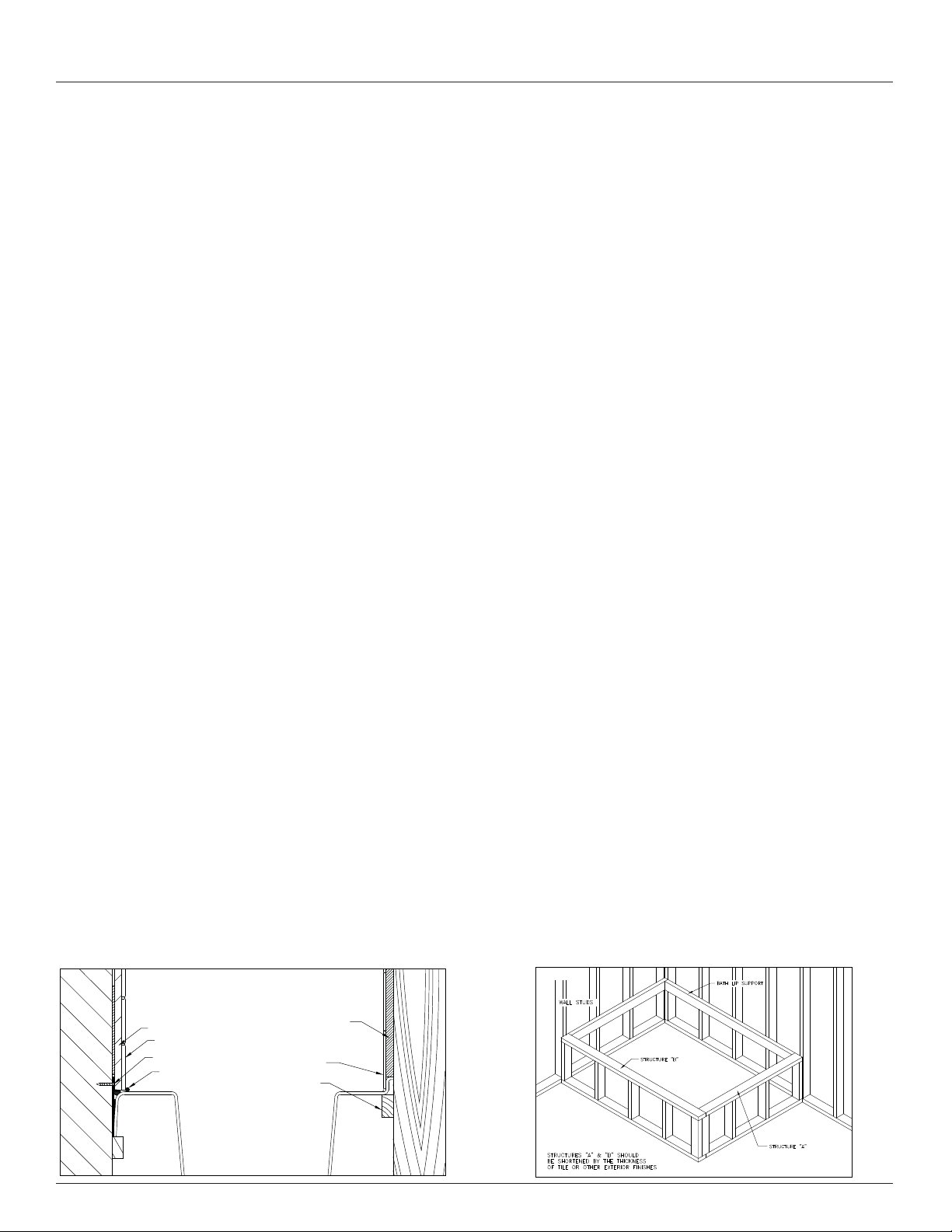
3. I N S TA L L S E R V I C E CO N N EC T I O N AT L E A S T 6" (15 c m)
ABOVE SUB FLOOR.
ALL LOCAL AND STATE ELECTRICAL AND PLUMB-
ING CODES MUST BE OBSERVED. Where there are
no local codes, the National Electric Code (NEC) and
Uniform Plumbing Code (UPC) shall be observed.
It is the responsibility of the installer/owner to determine
specific code compliance prior to installation of the
product.
NOTE:IntheCommonwealthofMassachusetts,installation
is to be done by a Massachusetts licensed plumber.
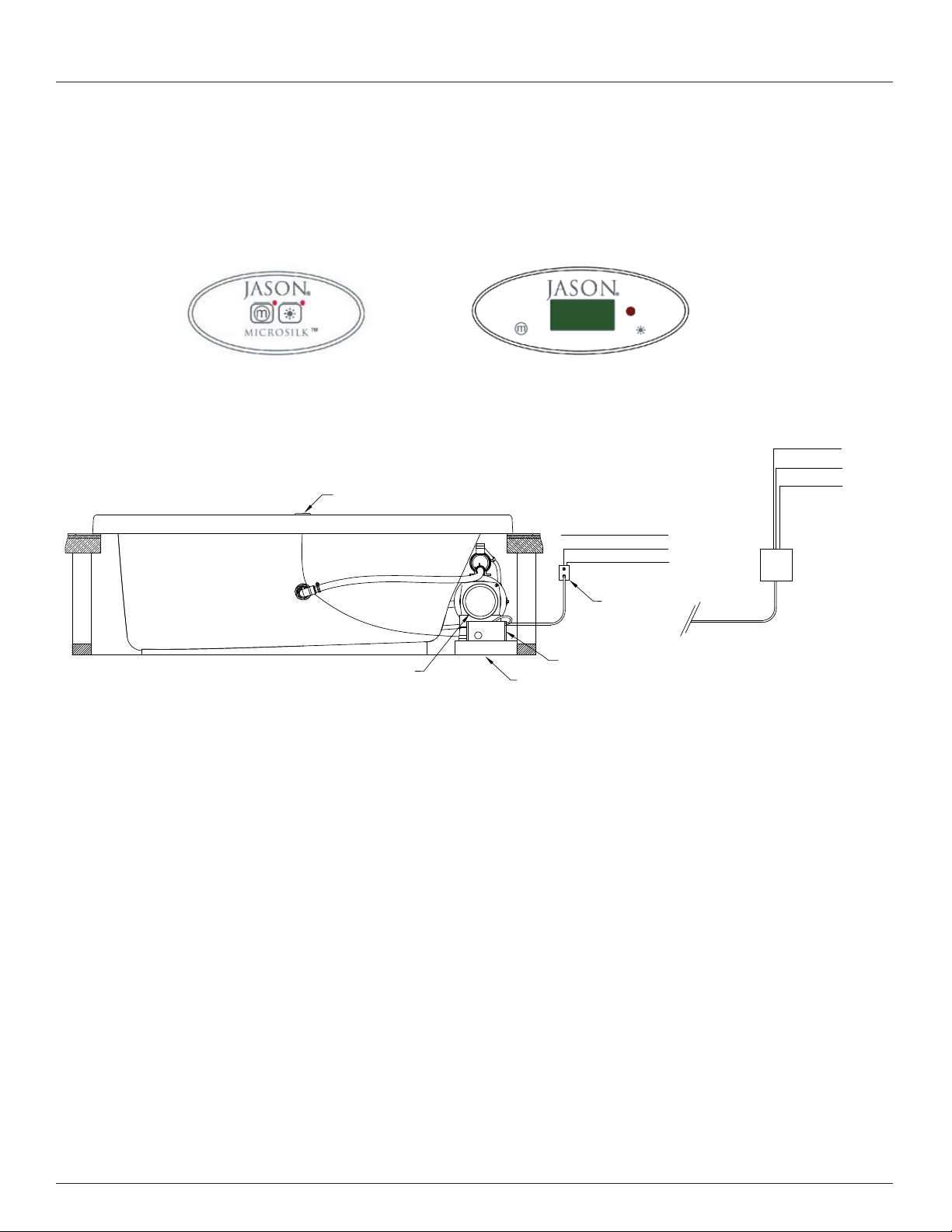
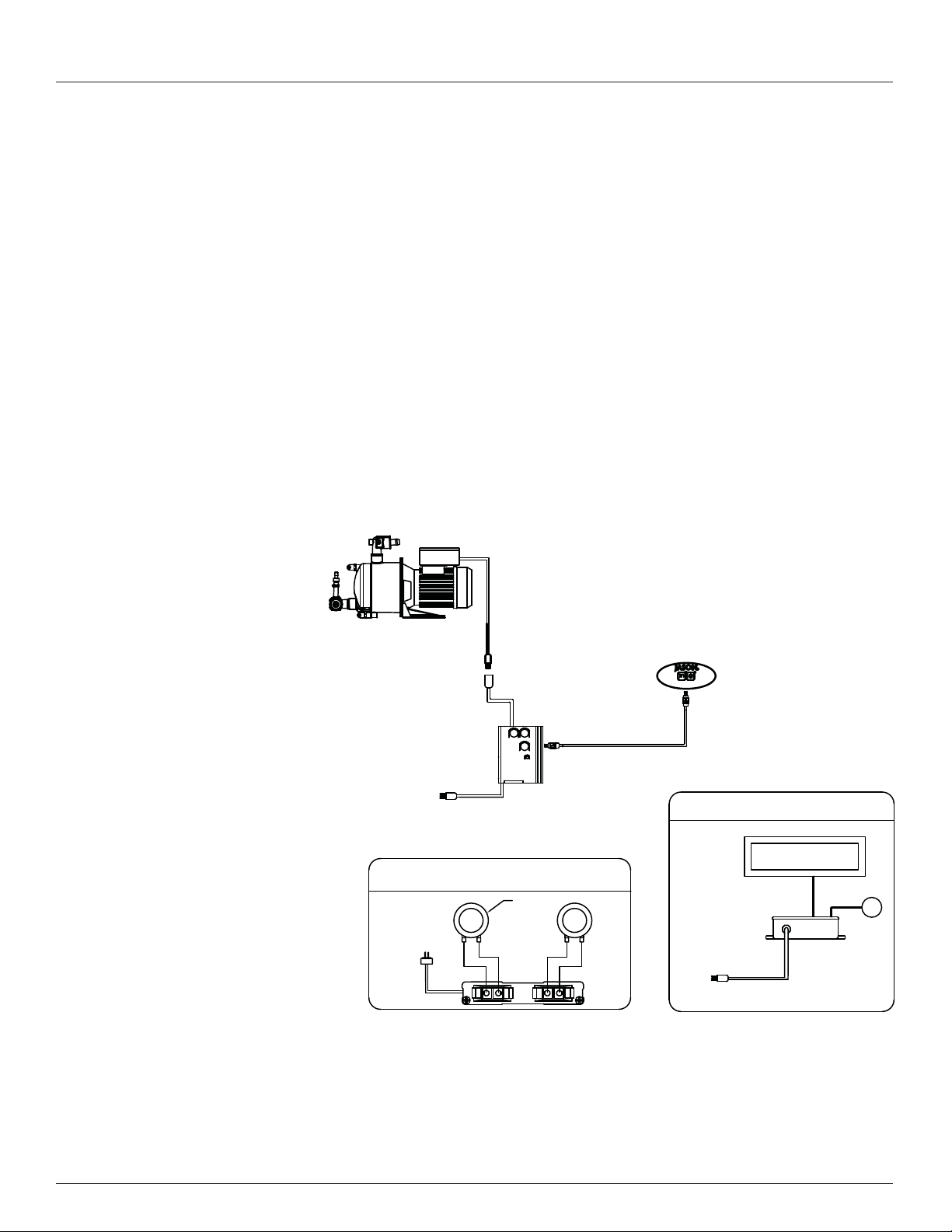
4. 120V Electrical Service- MicroSilk®Control Box.
TheMicroSilk®generatorunit may beshipped separatefrom
the bath. Follow the instructions for the MicroSilk®Pump
Assembly Field Installation in the Installation section of
this owner’smanual (instructions arealso packagedwiththe
MicroSilk®unit packaging). Thecontrolboxhas a36" (91cm)
cord with plug end. The MicroSilk®control box is mounted
on a stand that is temporarily secured to the packing board
for shipping. During installation, the control box bracket
and controls must be positioned horizontally and located
to permit access for inspection and servicing. If the Micro-
Silk®generator unit is shipped separate from the bath, the
MicroSilk®pump’s power cord will need to be plugged
into the control box. Connect the pump’s male NEMA
plug to the female NEMA plug of the control box’s
load line. The MicroSilk control must be plugged into
a dedicated 120V, 20A, 60Hz, GFCI protected circuit
(See Figure 8).
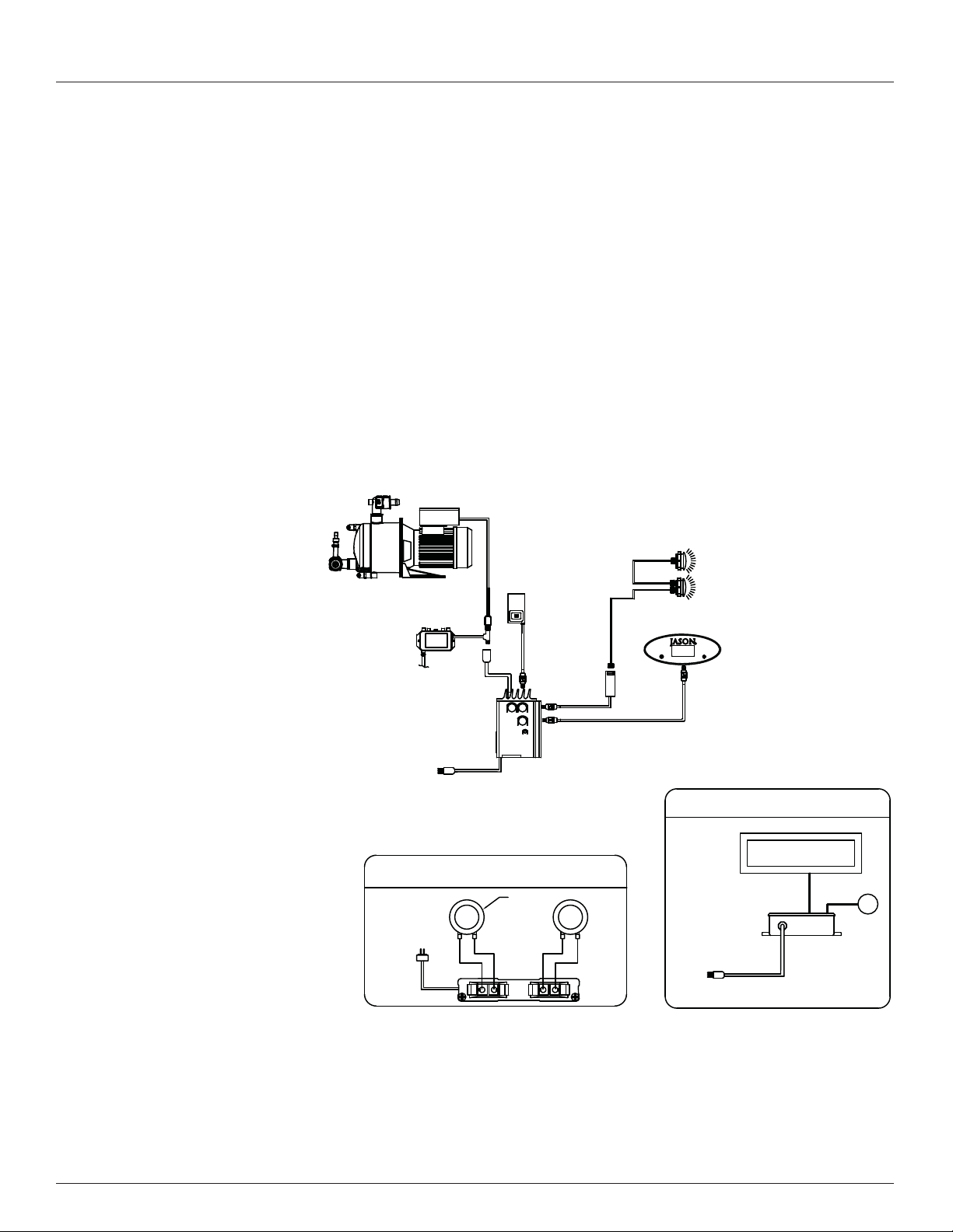
5. 240VElectricalService-MicroSilk®Control Box (Export).
TheMicroSilk®generatorunit may beshipped separatefrom
the bath. Follow the instructions for the MicroSilk®Pump
Assembly Field Installation in the Installation section of
this owner’smanual (instructions arealso packagedwiththe
MicroSilk®unit packaging). Thecontrolboxhas a36" (91cm)
cord with a junction box connection. The MicroSilk®control
box is mounted on a stand that is temporarily secured to the
packing board for shipping. During installation, the control
boxbracketand controlsmust bepositioned horizontallyand
located to permit access for inspection and servicing. If the
MicroSilk®generator unit is shipped separate from the
bath, the MicroSilk®pump’s power cord will need to be
plugged into the control box. Connect the pump’s male
J+J plug to the female J+J plug of the control box’s load
line. The MicroSilk®control must be plugged into a dedi-
cated 240V,vffgdg 20A, 50 or 60 Hz, GFCI protected circuit
(See Figure 8).
DANGER: Do not alter the factory installed wiring. All
building materials and wiring should be routed away from the
equipment or other heat-producing components of the unit.