JBI 0043 Installation and operation manual

John Berends
Implements Pty Ltd
AGRICULTURAL ENGINEERS
OPERATOR’SMANUAL
PARTSLIST
Stick Rakes
PRODUCT NO.
0043 6’ Stick Rake bottom only
0044 7’6” Stick Rake bottom only
0045 9’ Stick Rake bottom only
0046 10’6” Stick Rake bottom only
0138 Fixed Top
0139 Offset top
0342 7’6” Stick Rake complete with toolbar linkage – 15 tines
0343 9’ Stick Rake complete with toolbar linkage – 19 tines
0344 10’6” Stick Rake complete with toolbar linkage – 21 tines
130 FRANKSTON/DANDENONG RD, DANDENONG SOUTH, VIC. 3175 AUSTRALIA
PHONE (03) 9791 2494 FAX NO. (03) 9794 5568
www.johnberendsimplements.com.au

2
TABLEOFCONTENTS
PageNo.
SAFETY FEATURES............................................................................................. 3
SAFETY INSTRUCTIONS................................................................................... 6
ASSEMBLY.............................................................................................................7
OPERATION...........................................................................................................7
MAINTENANCE......................................................................................................8
SPARE PARTS.......................................................................................................8

3
SAFETY
Farm machinery is dangerous if operated incorrectly so please read this manual in its entirety
prior to operating the machine.
No operator, however experienced in farm machinery operation, should attempt to use
any machine they have not been competently trained to use. Your local Department of
Agriculture can help you with training, as can most Occupational Health and Safety offices,
Agricultural schools and colleges and farm equipment dealerships.
All instructions relating to tractor safety as per the tractor operators manual should be
followed. When making any machine adjustments, stop the tractor engine first and wait for all
moving parts to stop. Maintain the tractor to ensure it remains safe to use. Do not operate
faulty or damaged equipment.
Extreme caution should be taken when fitting equipment to the tractor’s three point
linkage. Avoid standing between the implement and the tractor when coupling machinery.
All machines should be mounted and retained correctly. All guards must be kept in
place and correctly maintained. P.T.O. shafts must be correctly attached and secured to both
the tractor and the machine. Decals must be visible and legible at all times. Keep well clear of
all moving parts.
Keep all people and animals at a safe distance from all moving parts. Children must not
be allowed to operate this equipment and all passengers must have the same level of
protection as the operator.
Wear protective clothing where appropriate.
Never operate when tired (not alert) or in poorly lit areas and stay alert for humps and
other hidden hazards. Remove all timber, rocks and foreign objects prior to operation.
Avoid operating the machine in wet conditions.
Exercise extreme caution when changing direction on hills. Avoid sudden movement,
sudden breaking, high speeds, rough terrain and steep slopes.

4
If machine starts to vibrate, stop tractor using method as described in the operation
section
After striking a foreign object or if the there are doubts about the performance of the
machine, stop the tractor as described and check if machine is making excessive noise.
Extreme caution must be taken when working in public areas (roadsides etc). It is
recommended that flaps and chains are fitted in these areas. These are available as optional
extras. Rear flaps are compulsory in public areas.
Do not modify this equipment in anyway, or use it for any other purpose than it was
designed to do.
Never work under unsupported machines or adjust unsupported machines. Do not
enter the danger zone where a load being carried by a machine could fall on you, for example
a round bale from a bale fork, a log from a carryall or material from a rear end loader.
These instructions should be used in conjunction with any local regulations regarding safety ie
OHS.
Maintenance is essential for safe operation. Ensure maintenance is carried out regularly
by people qualified to do so. This is of particular importance on P.T.O. drive machines
where driven parts can fly off at high speed if wearing parts are not properly maintained.
FAILURETOFOLLOWTHESEINSTRUCTIONSAND
PROCEDURESMAYRESULTINEQUIPMENT
MALFUNCTION,ORDAMAGE,SERIOUSINJURYOR
EVENDEATH.

5
INTRODUCTION:
This manual was developed specifically for the machine you have purchased. The information within is
to assist you in preparing, operating and maintaining your machine. Please read and understand the
contents of the manual completely before attempting to operate your machine, paying special attention
to all safety details. With our policy of continuous improvement, products and specifications may change
without notice and without incurring the obligation to install such changes on any unit previously
delivered.
Stick Rakes
The range of stick rakes come with the option of a fixed top (no offset), toolbar headstock or an offset top
which enables the rake to be operated outside the tractor wheels. All tines are spaced at 6” spacings and
are fitted with replaceable points and other points are available for different applications. The toolbar is
constructed from 2” square K1045 (high tensile) solid bar. Wheel kits can also be fitted to control depth.
MACHINESPECIFICATIONS
MODEL 6’ 7’6” 9’ 10’6”
No of tines 11 15 19 21
Tine Size 32 x 10 32 x 10 32 x 10 32 x 10
Tractor H.P. (minimum) 16 H.P. 16 H.P. 25 H.P. 35 H.P.
Tractor CAT connection Cat 1/2 Cat 1/2 Cat 1/2 Cat 1/2
Nett Weight (kg) 110 130 160 180
WARRANTY
John Berends Implements P/L warrants each new product sold to be free from defects in material and
workmanship, under normal use and service, as outlined in the operators manual, for a period of 12
months.
This warranty is void if any damage to the machine has been caused by misuse or non genuine parts
have been used or any repairs have been made by any persons other than authorised dealer service
personnel.
The manufacturer/dealer is not obligated to any transportation charges incurred in the repair or
replacement of parts.
This warranty does not exclude any condition or warranty implied by the Trade Practices Act 1974 or any
other legislation which implies any condition which cannot be excluded.
Copyright 1998 This Safety Manual is copyright and no part may be reproduced without
the written permission of John Berends Implements.

6
SafetyFeatures
1. SERIAL NUMBER (Decal)
2. WARNING DECAL
3. BERENDS DECAL
3
2
1

7
ASSEMBLY
Line the lower linkage arms between the lower linkage plates of the stick rake top, slide the
linkage pins through the holes and secure with linch pins. Attach the top link to the stick rake. It
may be helpful to support the linkage at the right height with a stable block or similar. Sway
chains or bars should be used to prevent the machine swinging around in use.
OPERATION
Once all safety procedures have been followed, start the tractor and raise the stick rake off the
ground
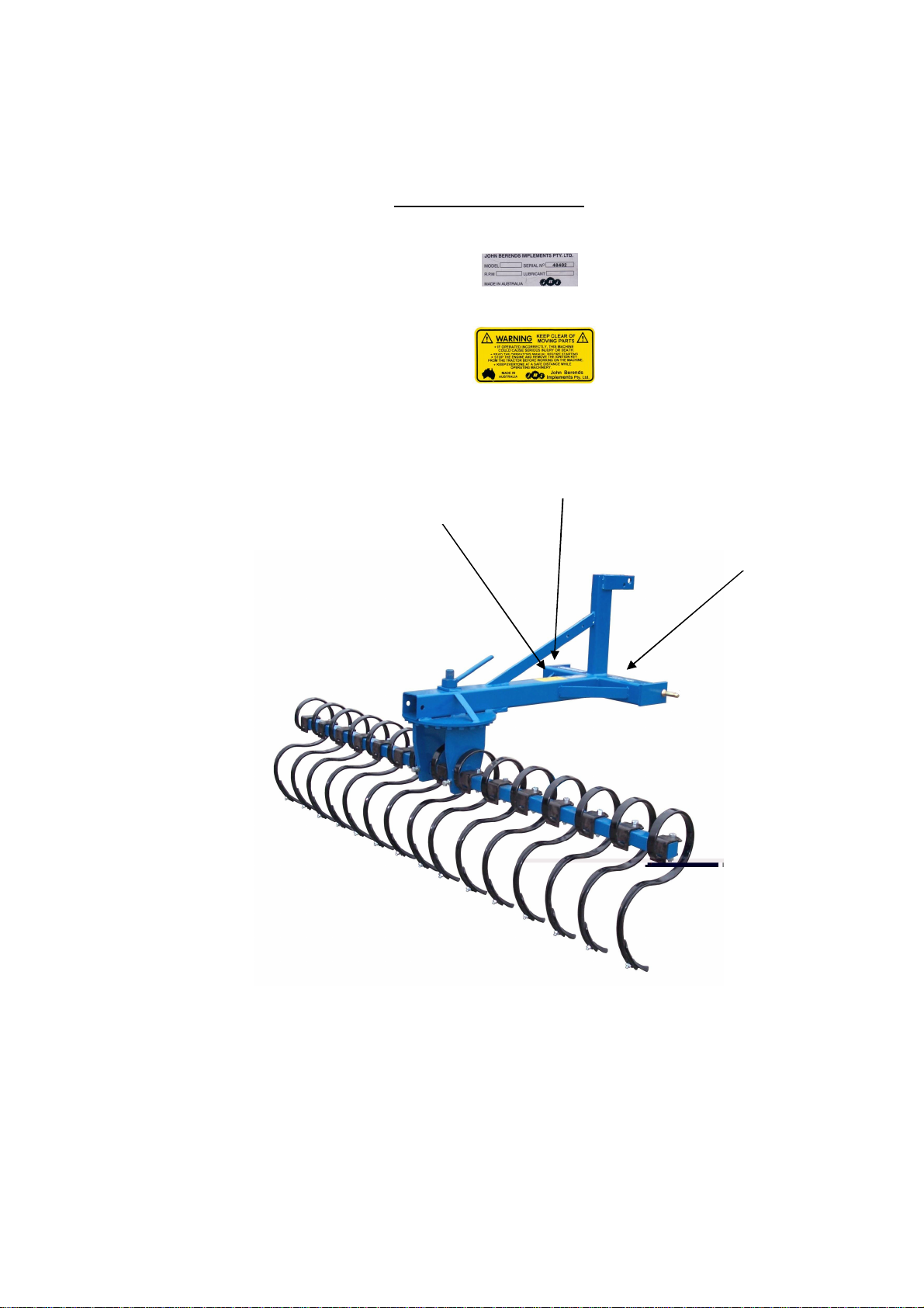
There are four positions of offset on either side of the rake (except for the standard fixed and
toolbar models). The offset adjusting arm has to be mounted on the side on which the rake is
required to be offset, left for left and right for right. It is adjusted by fitting the pin at the rear
end of the adjusting arm in one of the four alternative holes in the beam. To do this level the
machine so it will not swing around under its own weight, then remove the pin, move the rake
beam across until the hole in the offset arms lines up with a hole in the beam at the desired
offset.
The second adjustment is the angle. The rake is locked in position by a locking lug under the
beam and is held tight by the pivot nut handle. Loosen the handle so that the rake drops below
the locking index. This is best done by lifting the machine slightly off the ground using the
linkage arms on the tractor. Rotate the rake to the desired angle and ensure the angle
adjustment handle (nut handle) is secure. Apply some grease to the pivot pin to prevent it from
seizing up over time.
Always have the stick rake tines facing straight forward when operating to prevent tine
damage. You will only need to adjust the angle when altering the offset position.
Caution:
When adjusting any stick rake angle or offset, make sure the machine is level so it will not
swing around under its own weight.
The toolbar type can also be offset simply by knocking out the wedges holding the bar inside
the clamps and relocating the toolbar to one side. Knock the wedges back in with a hammer to
ensure they lock the toolbar inplace.
The offset model will tilt via the linkage pins. When connecting the stick rake, position the
tractors lower linkage arms in different holes to vary the tilt. The rake can be tilted from the
tractor using the levelling box without altering the pins. There are probably not many situations
where a stick rake will use a tilt function however it is still incorporated in the unit in case a
grader blade is mounted at any stage.
Caution:
Only operate the stick rake on even ground. If ground is undulating it is advised that depth
wheels be mounted on either side to prevent excessive force on outer tines.

8
Turning
Lift the stick rake off the ground. Never turn before the tines are completely free from the soil,
otherwise the inner most tines will be forced sideways and backwards. Alternatively a large
wide sweep can be taken providing the tines never move backward.
Reversing
Never reverse with the tines in the soil, but make sure the rake is fully raised. Reversing can
overload the tines eventually leading to tine breakage.
Stopping
Lower the stick rake, stop the tractor engine (removing the ignition key) and apply the park
brake. Ensure that the stick rake is well supported when not in use.
MAINTENANCE
When doing any type of maintenance on this machine, always follow the safety steps
described in this manual. Use only authorised genuine parts for replacement.
The stick rake must be adequately supported under its body (Make certain it cannot fall).
Tines
Check all tines clamps are tight. Ensure points are not too worn. If so they must be reversed or
replaced before they wear the tine out.
Wheel kit
Check tyre pressure. Wheel must run freely on axle and yoke must be lubricated.
Note: Bearings are replaceable if necessary.
SPARE PARTS
ORDER SPARE PARTS THROUGH YOUR ORIGINAL SUPPLIER OR YOUR LOCAL JOHN
BERENDS IMPLEMENTS DEALER.
Always quote the machine serial number or product number, spare part number and its part
name as stated in the operator’s manual.

9
10
1
2
3 & 4
5
6
7
8
9
11
Stick Rake (0044-0046, 0342-0344)
Key No. Part No.
Quantity Description
1 1670 ar Tine with point 32 x 10
2 3849 ar Clamp bracket, bolt/nut/sw to fit 1670 to 50 x 50 frame
3 1678 ar Reversible point
1684 ar Lucerne or grass point (optional)
4 1686 ar Plough bolt/nut
5 3850 1 7’6” high tensile toolbar only
3851 1 9’ high tensile toolbar only
3852 1 10’6” high tensile toolbar only
6 1514 1 Nut handle (angle adjustment on )
7 3853 1 Cog (angle) complete with pivot pin/support legs
8 1496 1 Pivot pin
9 3854 2 Toolbar locking bolts/square nuts
10 0587 2 Wedges hold clamp
11 1967 2 Cat 1 bolt on pin
This manual suits for next models
8
Table of contents