11
Neben den in der Gebrauchsanleitung
enthaltenen Sicherheitshinweisen und
den besonderen Vorschriften Ihres
Landes sind die für den Betrieb von
Holzbearbeitungsmaschinen
allgemein anerkannten
fachtechnischen Regeln zu beachten.
Jeder darüber hinaus gehende
Gebrauch gilt als nicht
bestimmungsgemäß und für daraus
resultierende Schäden haftet der
Hersteller nicht. Das Risiko trägt allein
der Benutzer.
3.2 Allgemeine Sicherheitshinweise
Holzbearbeitungsmaschinen können
bei unsachgemäßem Gebrauch
gefährlich sein. Deshalb ist zum
sicheren Betreiben die Beachtung der
zutreffenden Unfallverhütungs-
vorschritten und der nachfolgenden
Hinweise erforderlich.
Lesen und verstehen Sie die
komplette Gebrauchsanleitung bevor
Sie mit Montage oder Betrieb der
Maschine beginnen.
Bewahren Sie die
Bedienungsanleitung, geschützt vor
Schmutz und Feuchtigkeit, bei der
Maschine auf, und geben Sie sie an
einen neuen Eigentümer weiter.
An der Maschine dürfen keine
Veränderungen, An- und Umbauten
vorgenommen werden.
Überprüfen Sie täglich vor dem
Einschalten der Maschine die
einwandfreie Funktion und das
Vorhandensein der erforderlichen
Schutzeinrichtungen.
Festgestellte Mängel an der Maschine
oder den Sicherheitseinrichtungen
sind zu melden und von den
beauftragten Personen zu beheben.
Nehmen Sie die Maschine in solchen
Fällen nicht in Betrieb, sichern Sie die
Maschine gegen Einschalten durch
Ziehen des Netzsteckers.
Zum Schutz von langem Kopfhaar
Mütze oder Haarnetz aufsetzen.
Enganliegende Kleidung tragen.
Schmuck, Ringe und Armbanduhren
ablegen.
Tragen Sie Schutzschuhe, keinesfalls
Freizeitschuhe oder Sandalen.
Verwenden Sie die durch Vorschriften
geforderte persönliche
Schutzausrüstung.
-Augenschutz
-Gehörschutz
-Staubschutz
Beim Arbeiten mit der Maschine keine
Handschuhe tragen.
Zum sicheren Handhaben der
Fräswerkzeuge geeignete
Arbeitshandschuhe tragen.
Beachten Sie das in dieser
Betriebsanleitung enthaltene Kapitel
zu den Sicheren Arbeitsweisen.
Achten Sie auf die gebremste
Auslaufzeit der Maschine, sie darf in
keinem Fall 10 s übersteigen.
Eingeklemmte Werkstücke nur bei
ausgeschaltetem Motor und Stillstand
der Maschine entfernen.
Die Maschine so aufstellen, dass
genügend Platz zum Bedienen und
zum Führen der Werkstücke gegeben
ist.
Sorgen Sie für gute Beleuchtung.
Achten Sie darauf, dass die Maschine
standsicher auf festem und ebenem
Grund steht.
Beachten Sie dass die elektrische
Zuleitung nicht den Arbeitsablauf
behindert und nicht zur Stolperstelle
wird.
Den Arbeitsplatz frei von
behindernden Werkstücken, etc.
halten.
Seien Sie aufmerksam und
konzentriert. Gehen Sie mit Vernunft
an die Arbeit.
Achten Sie auf ergonomische
Körperhaltung.
Sorgen Sie für sicheren Stand und
halten Sie jederzeit das Gleichgewicht.
Arbeiten Sie niemals unter dem
Einfluss von Rauschmitteln wie
Alkohol und Drogen an der Maschine.
Beachten Sie, dass auch
Medikamente Einfluss auf Ihr
Verhalten nehmen können.
Halten Sie Unbeteiligte, insbesondere
Kinder vom Gefahrenbereich fern.
Entfernen Sie keine Späne,
Werkstücke und Werkstückabschnitte
bevor die Maschine stillsteht.
Die laufende Maschine nie
unbeaufsichtigt lassen.
Vor dem Verlassen des Arbeitsplatzes
die Maschine ausschalten.
Benützen Sie die Maschine nicht in
der Nähe von brennbaren
Flüssigkeiten oder Gasen.
Beachten Sie die Brandmelde- und
Brandbekämpfungsmöglichkeiten z.B.
Standort und Bedienung von
Feuerlöschern.
Benützen Sie die Maschine nicht in
feuchter Umgebung und setzen Sie sie
nicht dem Regen aus.
Achten Sie stets darauf, dass keine zu
große Staubkonzentration entsteht –
verwenden Sie stets eine geeignete
Absauganlage.
Holzstaub ist explosiv und kann
gesundheitsschädigend sein.
Insbesondere tropische Hölzer und
harte Hölzer wie Buche und Eiche sind
als krebserregend eingestuft.
Vor der Bearbeitung Nägel und andere
Fremdkörper aus dem Werkstück
entfernen.
Die Maschine niemals mit abgebauten
Schutzeinrichtungen betreiben. Hohe
Verletzungsgefahr!
Verwenden Sie je nach Einsatzzweck
die entsprechende Schutzeinrichtung,
die ein sicheres Führen des
Werkstückes gewährleistet.
Passen Sie die Schutzeinrichtung
genau an den Einsatzzweck und die
Weckstückabmessungen an.
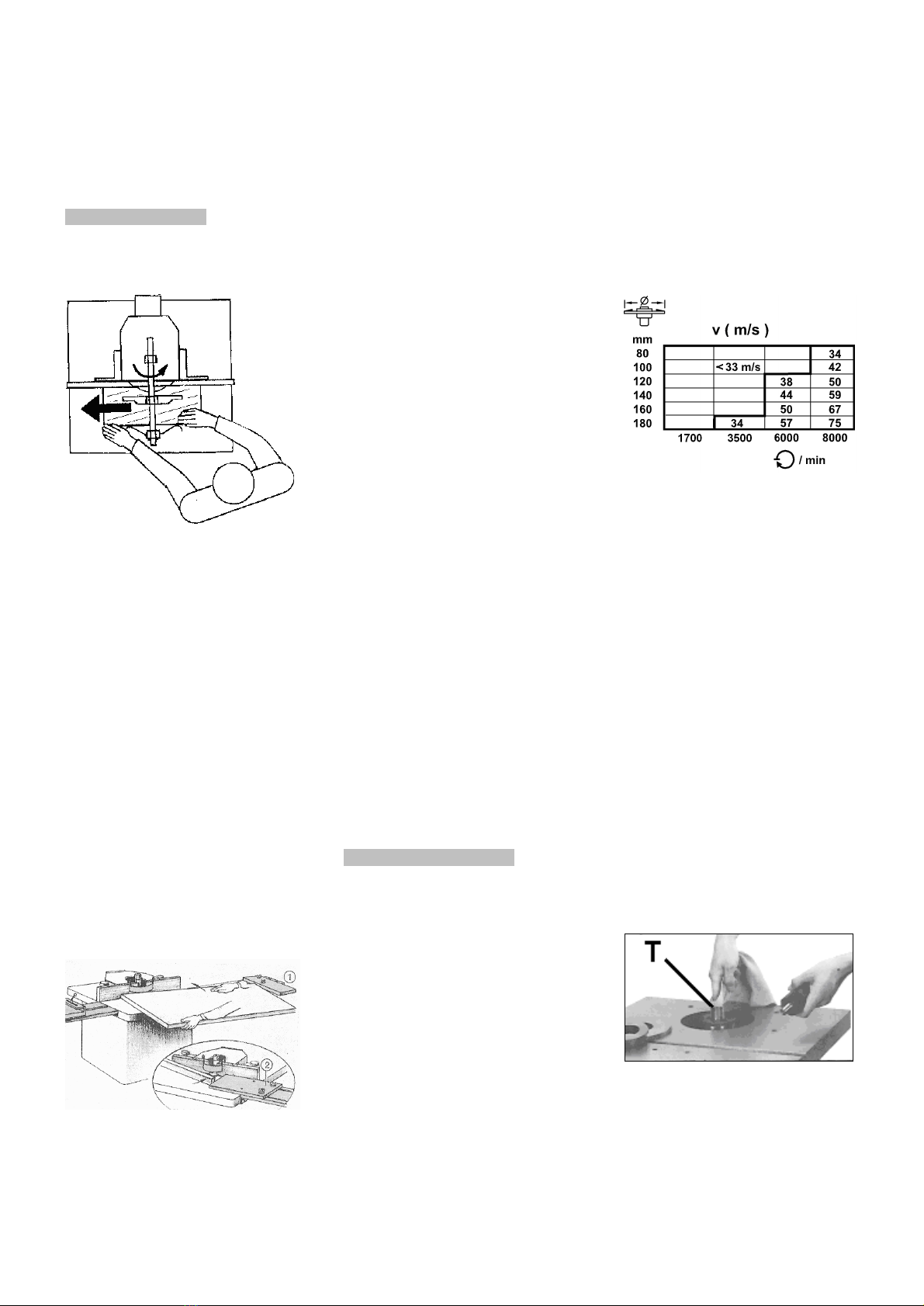
Passen Sie die Frässpindeldrehzahl
an den Werkzeugdurchmesser an.
Halten Sie immer ausreichend
Abstand zum Fräswerkzeug.
Fassen Sie beim Führen des
Werkstücks niemals mit den Händen
unter den Frässchutz!
Bearbeiten Sie nur ein Werkstück, das
sicher auf dem Tisch aufliegt.
Das Werkstück nur gegen die
Fräserlaufrichtung vorschieben.
Bei Werkstücklängen unter 300mm
sind besondere Hilfsmittel (z.B.
Schiebelade) erforderlich.
Bearbeiten Sie kein Werkstück
welches nicht mit einem
ausreichenden Sicherheitsabstand
zum Fräswerkzeug geführt werden
kann.
Zapfenschneiden und Schlitzen
erfordern die optional erhältliche
Zapfenschneid Vorrichtung.
Bei schmalen Werkstücken am Ende
der Bearbeitung mit dem Schiebeholz
vorschieben.
Der Schiebestock oder der Handgriff
für eine Schiebeholz sollte bei
Nichtbenützung immer an der
Maschine aufbewahrt werden.
Die min. und max.
Werkstückabmessungen müssen
eingehalten werden.
Späne und Werkstücke nur bei
stehender Maschine entfernen.