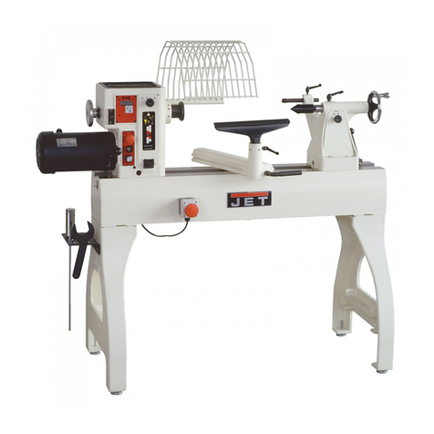
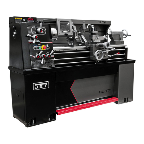
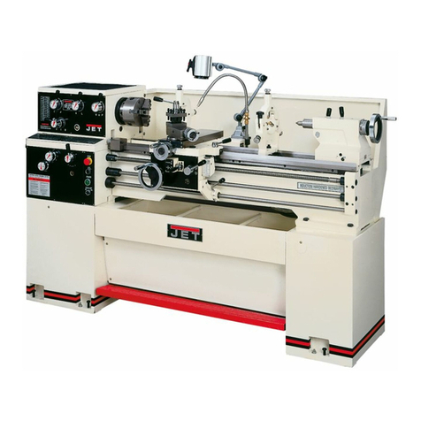
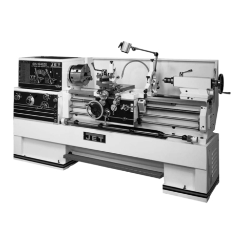
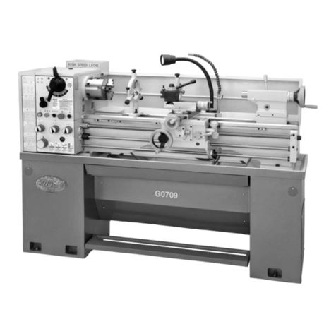
Jet GH-1640ZX User manual

3
GB - ENGLISH
Operating Instructions
Dear Customer,
Many thanks for the confidence you have shown in us with the purchase of your new JET-machine. This manual has been
prepared for the owner and operators of a JET GH-1640/ 1840/ 1860/ 1880/ 2260/ 2280 ZX metal lathe to promote safety during
installation, operation and maintenance procedures. Please read and understand the information contained in these operating
instructions and the accompanying documents. To obtain maximum life and efficiency from your machine, and to use the
machine safely, read this manual thoroughly and follow instructions carefully.
…Table of Contents
1. Declaration of conformity
2. Warranty
3. Safety
Authorized use
General safety notes
Remaining hazards
4. Machine specifications
Technical data
Noise emission
Contents of delivery
Machine description
5. Transport and start up
Transport and installation
Assembly
Mains connection
Initial lubrication
Starting operation
Break in procedure
6. Machine operation
Controls
Chucking
Tool setup
Spindle speed selection
Turning with auto feed
Thread cutting
Drilling operation
Z-axis rapid feed (option)
7. Setup and adjustments
Turning between centres
Taper turning with tailstock
Taper turning with top slide
Three jaw universal chuck
Four jaw independent chuck
Live centre
Steady and follow rest
Bed gap removal
8. Maintenance and inspection
Annual lubrication
Weekly lubrication
Daily lubrication
Slide adjustments
Shear pin replacement
Headstock alignment
Coolant system
9. Trouble shooting
10. Environmental protection
11. Available accessories
1. Declaration of conformity
On our own responsibility we hereby declare that this
product complies with the regulations* listed on page 2.
Designed in consideration with the standards**.
2. Warranty
The Seller guarantees that the supplied product is free from
material defects and manufacturing faults. This warranty
does not cover any defects which are caused, either directly
or indirectly, by incorrect use, carelessness, accidental
damage, repair, inadequate maintenance or cleaning and
normal wear and tear.
Guarantee and/or warranty claims must be made within
twelve months from the date of purchase (date of invoice).
Any further claims shall be excluded.
This warranty includes all guarantee obligations of the Seller
and replaces all previous declarations and agreements
concerning warranties.
The warranty period is valid for eight hours of daily use. If
this is exceeded, the warranty period shall be reduced in
proportion to the excess use, but to no less than three
months.
Returning rejected goods requires the prior express consent
of the Seller and is at the Buyer’s risk and expense.
Further warranty details can be found in the General Terms
and Conditions (GTC). The GTC can be viewed at
www.jettools.com or can be sent by post upon request.
The Seller reserves the right to make changes to the product
and accessories at any time.
3. Safety
3.1 Authorized use
This metal lathe is designed for turning and drilling
machinable metal and plastic materials only. Machining of
other materials is not permitted and may be carried out in
specific cases only after consulting with the manufacturer.
Never cut magnesium-
high danger to fire!
The workpiece must allow to safely be loaded and clamped.

4
The proper use also includes compliance with the operating
and maintenance instructions given in this manual.
The machine must be operated only by persons familiar with
its operation and maintenance and who are familiar with its
hazards.
The required minimum age must be observed.
The machine must only be used in a technically perfect
condition.
When working on the machine, all safety mechanisms and
covers must be mounted.
In addition to the safety requirements contained in these
operating instructions and your country’s applicable
regulations, you should observe the generally recognized
technical rules concerning the operation of metalworking
machines.
Any other use exceeds authorization.
In the event of unauthorized use of the machine, the
manufacturer renounces all liability and the responsibility is
transferred exclusively to the operator.
3.2 General safety notes
Metalworking machines can be dangerous if not used
properly. Therefore the appropriate general technical rules
as well as the following notes must be observed.
Read and understand the entire instruction manual before
attempting assembly or operation.
Keep this operating instruction close by the machine,
protected from dirt and humidity, and pass it over to the new
owner if you part with the tool.
No changes to the machine may be made.
Daily inspect the function and existence of the safety
appliances before you start the machine.
Do not attempt operation in this case, protect the machine
by unplugging the power cord.
Remove all loose clothing and confine long hair.
Before operating the machine, remove tie, rings, watches,
other jewellery, and roll up sleeves above the elbows.
Wear safety shoes; never wear leisure shoes or sandals.
Always wear the approved working outfit.
Do not wear gloves.
Wear goggles when working
Install the machine so that there is sufficient space for safe
operation and work piece handling.
Keep work area well lighted.
The machine is designed to operate in closed rooms and
must be placed stable on firm and levelled ground.
Make sure that the power cord does not impede work and
cause people to trip.
Keep the floor around the machine clean and free of scrap
material, oil and grease.
Stay alert!
Give your work undivided attention. Use common sense. Do
not operate the machine when you are tired.
Keep an ergonomic body position.
Maintain a balanced stance at all times.
Do not operate the machine under the influence of drugs,
alcohol or any medication. Be aware that medication can
change your behaviour.
Never reach into the machine while it is operating or running
down.
Never leave a running machine unattended. Before you
leave the workplace switch off the machine.
Keep children and visitors a safe distance from the work
area.
Do not operate the electric tool near inflammable liquids or
gases.
Observe the fire fighting and fire alert options, for example
the fire extinguisher operation and place.
Do not use the machine in a dump environment and do not
expose it to rain.
Work only with well sharpened tools.
Always close the chuck guard and pulley cover before you
start the machine.
Remove the chuck key and wrenches before machine
operation.
Specifications regarding the maximum or minimum size of
the work piece must be observed.
Do not remove chips and work piece parts until the machine
is at a standstill.
Do not stand on the machine.
Connection and repair work on the electrical installation may
be carried out by a qualified electrician only.
Have a damaged or worn power cord replaced immediately.
Never place your fingers in a position where they could
contact any rotating parts or chips.
Check the save clamping of the work piece before starting
the machine.
Don’t exceed the clamping range of the chuck.
Work pieces longer than 3 times the chucking diameter
need to be supported by the tailstock or a steady rest.
Avoid small chucking diameters at big turning diameters.
Avoid short chucking lengths.
Avoid small chucking contact.
Never exceed the max speed limitation of the work holding
device.
Choose a small spindle speed when working unbalanced
work pieces and for threading and tapping operations.
Any work piece stock extending the rear end of the
headstock must be covered on its entire length. High danger
of injury!
Long work pieces may need a steady rest support. A long
and thin work piece can suddenly bend at high speed
rotation.
Never move the tailstock or tailstock quill while the machine
is running.
5
Remove cutting chips with the aid of an appropriate chip
hook when the machine is at a standstill only.
Never stop the rotating chuck or work piece with your hands.
Measurements and adjustments may be carried out when
the machine is at a standstill only.
Setup, maintenance and repair work may only be carried out
after the machine is protected against accidental starting by
pulling the mains plug.
3.3 Remaining hazards
When using the machine according to regulations some
remaining hazards may still exist.
The rotating work piece and chuck can cause injury.
Thrown and hot work pieces and cutting chips can lead to
injury.
Chips and noise can be health hazards. Be sure to wear
personal protection gear such as safety goggles and ear
protection.
The use of incorrect mains supply or a damaged power cord
can lead to injuries caused by electricity.
4. Machine specifications
4.1 Technical data
GH-1640 (1840/ 1860/ 1880) [2260/ 2280] ZX:
Swing over bed 406(460) [560]mm
Swing over bed gap 657 (698) [775]mm
Swing over cross slide 254 (280) [350]mm
Centre distance 1015/ 1524/ 2032mm
Width of bed 340 mm
Spindle taper MT-7
Spindle nose DIN 55029 D1-8
(Camlock)
Hole through spindle ∅80 mm
Spindle speeds…12 25-1800 rpm
Tailstock ram travel 124mm
Tailstock taper MT4 [(MT-5)]
Steady rest capacity 12 – 178 mm
Follow rest capacity 15 – 90 mm
Cross slide travel 228 [280] mm
Top slide travel 130 mm
Tool size max 25 x 25 mm
Longitudinal feeds 122
0,038–2,3mm/r
Cross feeds 122
0,015-0,9 mm/r
Metric threads...24 0,5–20 mm/r
Inch threads…61 1 5/8 – 72 TPI
Modular Pitch 20 0,25 – 10MP
Diametral Pitch 45 96 – 3 ¼ DP
Lead screw pitch 6 mm
Coolant tank capacity 15 L
GH-1640 (1840 / 1860 / 1880)ZX:
Overall L x W x H
2462 (2462/ 2960/ 3458) x 1016 x 1220 (1241) mm
Net weight 2483 ( 2712 / 2832 / 2988) kg
Mains 400V ~3L/PE 50Hz
Output power 5,5 kW (7,5 HP) S1
Reference current 14 A
Extension cord (H07RN-F): 4x4 mm²
Installation fuse protection 25A
GH-2260 / 2280 ZX:
Overall L x W x H 2960 / 3458 x 1016 x 1291 mm
Net weight 2900 / 3145 kg
Mains 400V ~3L/PE 50Hz
Output power 7,5 kW (10 HP) S1
Reference current 18A
Extension cord (H07RN-F) 4x4 mm²
Installation fuse protection 25A
Z-axis rapid feed (option):
rapid feed speed 5 m/min
4.2 Noise emission
Acoustic pressure level (according to EN ISO 11202):
Idling at maximum speed LpA 81,2 dB(A)
The specified values are emission levels and are not
necessarily to be seen as safe operating levels.
As workplace conditions vary, this information is intended to
allow the user to make a better estimation of the hazards
and risks involved only.
4.3 Content of delivery
Cast iron stand
6 Leveling pads
Pull out chip tray
Splash guard
250mm 3-jaw universal chuck
400mm 4-jaw independent chuck (300mm/ GH-1640ZX)
300mm faceplate
Four way tool post
Steady rest
Follow rest
Foot brake
Coolant system
Halogen work light
MT-5 life centre
(MT-4/ GH-1640ZX)
MT-5 fixed centre
MT-5/MT-7 centre sleeve
Threading dial
Operating tools in tool box
Oil can
Operating manual
Spare parts list.

6
4.4 Machine description
Fig 1
A….Lathe bed
B….Headstock
C….Carriage
D….Top slide
E….Cross slide
F….Four way tool post
G….Apron
Fig 2-1
A…..Tailstock
B…..Lead screw
C…..Feed rod
D….Gear box
E…..Follow rest
F…..Steady rest
Fig 2-2
N….Pulley cover
O.….Chuck guard
P….Tool post guard
Q……Halogen machine light
R…...3-axis digital readout (option)
S…..Coolant nozzle
5. Transport and start up
5.1 Transport and installation
The machine will be delivered in a closed crate.
For transport use a forklift or hand trolley. Make sure the
machine does not tip or fall off during transport.
The machine is designed to operate in closed rooms and
must have sufficient floor space to operate it and to have
access from all sides.
Floor plan see appendix.
5.2 Assembly
If you notice transport damage while unpacking, notify your
supplier immediately. Do not operate the machine!
Dispose of the packing in an environmentally friendly
manner.
Clean all rust protected surfaces with petroleum, diesel oil or
a mild solvent.
Unbolt the lathe from the shipping crate bottom.
Move the tailstock to the tailstock end of the bed.
Place 2 steel rods of sufficient strength into 2 holes of lathe
bed.
Sling the lathe with properly rated straps ( Fig 3-1)

7
Fig 3-1
Caution:
The machine is heavy!
GH 1640 ZX 2483 kg
GH 1840 ZX 2712 kg
GH 1860 ZX 2832 kg
GH 1880 ZX 2988 kg
GH 2260 ZX 2900 kg
GH 2280 ZX 3100 kg
Use great care.
Assure the sufficient load capacity and proper condition
of your lifting devices.
Never step underneath suspended loads.
Fig 3-2
For lifting the machine with a forklift, use wooden riser
blocks to avoid foot pedal damage (Fig 3-2).
Attention:
The machine is left weighted. The center of weight is near
the headstock.
Foundation:
The machine must be installed on a solid foundation.
Leveling:
Use a machinist’s precision level on the bed ways and check
to make sure that the lathe bed is level.
The lathe bed must be level to be accurate.
a) Deviation over bed length max 0,02/1000mm
b) Deviation over bed length max 0,04/1000mm
5.3 Mains connection
Mains connection and any extension cords used must
comply with applicable regulations.
The mains voltage must comply with the information on the
machine licence plate.
The mains connection must have a
25 A surge-proof fuse.
Only use power cords marked H07RN-F
Connections and repairs to the electrical equipment may
only be carried out by qualified electricians.
Connection takes place on the terminal box on the back of
the machine.
5.4 Initial lubrication
The lathe must be serviced at all lubrication points and all
reservoirs filled to operating level before the lathe is placed
into service!
Failure to comply may cause serious damage to the lathe!
(see chapter 8 for lubrication).
After one month of operation the oil must be changed
on headstock, gearbox and apron.
The coolant tank has to be filled with coolant (see chapter
8.7)
5.5 Starting operation
Before starting the machine check the proper chucking
(see chapter 6.2).
Turn ON the main power switch (located on the electric box
at the rear of the machine).
You can now start the machine with the forward/ reverse
lever (A, Fig 4).

8
Fig 4
Push the lever
- right and down for forward rotation
-right and up for backward rotation.
Return the lever to its 0-position to stop the machine.
The spindle jog button (D, Fig 6) advances the spindle
momentarily.
The foot break will stop all lathe functions and break down
the spindle rotation.
Attention:
Lathe still has electric power.
The emergency stop button (C, Fig 6) stops all machine
functions.
Attention:
Lathe still has electric power.
Turn emergency stop button clockwise to reset.
Note:
The pulley cover (N, Fig 2-2) and the chuck guard (O) are
limit switch protected. They must be closed to operate the
machine.
5.6 Break in procedure:
To allow time for the gears and bearings to break-in and run
smoothly, do not run the lathe above 560 rpm for the first 6
hours.
6. Machine operation
Warning:
Setup work may only be carried out after the machine is
protected against accidental starting.
With pressed emergency stop button.
Measurements and adjustments may be carried out when
the machine is at a standstill only.
Check the save clamping of the work piece before starting
the machine.
Never stop the rotating chuck or work piece with your hands.
Never place your fingers in a position where they could
contact any rotating parts or chips.
Remove cutting chips with the aid of an appropriate chip
hook when the machine is at a standstill only.
Always close the chuck guard and pulley cover before you
start the machine.
Choose a small spindle speed when working unbalanced
work pieces and for threading and tapping operations.
Never cut magnesium-
high danger to fire!
In case of danger step on the foot break and press the
emergency stop button.
6.1 Controls
Fig 5
A….Foot break
B….Micro stop for carriage
C….Bed cover (remove for cleaning)

9
Fig 6
A….Coolant On/Off switch
B…. Spindle jog button
C….Emergency stop button
D…. Power indicator light
(shows that electric power is on)
E….Feed reversing lever
F….Sindle speed levers
H….Feed / Lead selector levers
F, D…for feed rod
E, C…for lead screw
Fig 7-1
A…..Cross slide lock
B…..Carriage lock
C….Longitudinal travel hand wheel
D…..Half-nut lever (thread cutting)
E…..Automatic Ffed lever
longitudinal feed …..push left and down
cross feed…………..push right and up
F…..Adjustable feed clutch
G…..Feed engage lever
H…..Cross slide hand wheel
J……Top slide hand wheel
K…..Tool post clamping lever
Z-axis rapid feed (option):
Fig 7-2
M…..Rapid feed select switch left/right
N…..Emergency stop button
Fig 8
A….Tailstock spindle locking lever
B.….Tailstock locking lever
C….Tailstock spindle hand wheel
D….Tailstock off-set adjustment

10
6.2 Chucking
Chuck removal:
Before removing the chuck from the spindle, place board
across the bed ways under the chuck.
Support the chuck while turning three cam locks ¼ turn
counter-clockwise.
Line up the two marks (A, Fig 9) for removal.
Fig 9
Carefully remove the chuck form the spindle.
Clean all contact surfaces.
Mounting the chuck:
Lift the chuck up to the spindle nose and press onto the
spindle.
Tighten in place by turning the cam locks ¼ turn clockwise.
The index mark (A) on the camlock should be between the
two indicator arrows (B).
If not, adjust the cam studs by turning them in or out by one
turn as needed.
Tighten cam locks.
Attention:
Never exceed the max speed limitation of the work holding
device.
Jaw teeth and scroll must always be fully engaged.
Otherwise chuck jaws may break and fly off in rotation (Fig
10).
Fig 10
Avoid long workpiece extensions. Parts may bend (Fig 11)
or fly off (Fig 12).
Use tailstock or rests to support.
Fig 11
Fig 12
Avoid short clamping contact (A, Fig 13) or clamping on a
minor part diameter (B).
Fig 13
Face locate the workpiece for added support.

11
6.3 Tool setup
The cutting angle is correct when the cutting edge is in line
with the centre axis of the work piece. Use the point of the
tailstock centre as a gauge and shims under the tool to
obtain the correct centre height.
Use a minimum of two clamping screws when installing the
cutting tool to the four way tool post.
Avoid big tool extensions.
6.4 Spindle speeds selection
The correct spindle speed depends on the type of
machining, the cutting diameter, the material to be
machined and the cutting tool.
These are recommended max. speeds for a 50mm cutting
diameter with carbide (HM) tools:
Aluminium, brass 1500 RPM
Cast iron 1000 RPM
Mild steel 800 RPM
High carbon steel 600 RPM
Stainless steel 300 RPM
If high speed steel (HSS) tools are used about 5 times lower
speeds must be chosen.
Generally speaking, the larger in relation the cutting
diameter, the smaller the possible RPM.
For example:
Turning mild steel at a diameter of 25mm allows a speed of
1600 RPM max. with carbide tool
320 RPM max. with HSS tool
To change the spindle speed:
The speed may never be changed when the spindle or motor
are still running.
Move the speed select levers (F, Fig 6) according to the
speed you desire.
It may be necessary to turn the chuck by hand to help the
gears to engage.
6.5 Turning with auto feed
Several automatic longitudinal and cross feeds are readily
available by selection on the gearbox levers
(E, F, H, G, Fig 14).
Fig 14
Set the lever G to the feed ( ) position….in this position
the lead screw is disengaged.
The feed direction can be chosen with the feed reversing
lever (A, Fig 14).
Do not shift levers while the machine is running.
Move the lever (D, Fig 15):
- for longitudinal feed…….left and down
- for cross feed…………....right and up
Fig 15

12
The correct feed depends on the material to be cut, the
cutting operation, the type of tool, the rigidity of the
work piece chucking, the depth of cut and the desired
surface quality.
For example:
Longitudinal OD-turning, mild steel of 25mm diameter with
a carbide tool at 1400 RPM and with rigid chucking.
Stock removal and roughing cut:
Depth of cut 2mm
Feed per revolution 0,2mm
(change gear box position 4, G and I )
Finishing cut:
Depth of cut 0,5mm
Feed per revolution 0.1mm
(change gear box position 4, G and II )
Micro finishing and calibration cut:
Depth of cut 0,2mm
Feed per revolution 0.05mm
(change gear box position 4, G and III )
When roughing big diameters reduce the depth of cut!
6.6 Thread cutting
Threading is performed in multiple passes with a threading
tool.
Each depth of cut should be about 0,2mm and become less
for the finishing passes.
The threading direction can be chosen with the feed
reversing lever (A, Fig 14).
Set the feed rate selectors (E, F, G, H, Fig 14) in proper
position.
A) To cut inch and metric threads
Set the machine up for the desired threading pitch and first
depth of cut.
Engage the halve nut (A, Fig 15).
The halve nut must be engaged during the entire threading
process.
- Start the machine at the lowest spindle speed.
- When the tool reaches the end of cut, stop the motor and
at the same time back the tool out of the part so that it
clears the thread (Attention inertia: Stop the motor in time)
- Reverse the motor direction to allow the cutting tool to
travel back to the starting point.
Repeat these steps until you have obtained the desired
results.
B) To cut metric threads with threading dial:
On most metric threads the threading dial can be used.
The halve nut can be opened at the end of cut, rather than
the motor being stopped and reversed.
The halve nut may only be engaged at the corresponding
graduation match on the threading dial (see Fig 16)
Fig 16
For thread pitches of 0,5 / 0,6 / 0,75 / 1 / 1,5 / 2 / 3 / 6 mm
the halfe nut can be engaged at any time.
(lead screw pitch = 6 mm = dividable by thread pitch).
6.7 Drilling operation
Use a drill chuck with MT-4(MT-5) arbour (option) to hold
centring drills and twisted drills in the tailstock.
For recommended speedsrefer to section 6.4
To eject the drill chuck, fully retract the tailstock quill.

13
6.8 Z-axis rapid feed (option)
Fig 17
When Z-axis rapid feed is needed:
- Disengage the longitudinal travel handwheel (C, Fig 7).
- Disengage the auto feed
set lever (G, Fig 7) to the position (push down).
- Engage the longitudinal feed.
set lever (E, Fig17) to the position
(push left and down).
- Rotate the rapid feed switch (M, Fig 17) in the desired
direction
Warning:
Before operating the Z-axis rapid feed, the longitudinal travel
handwheel (C, Fig7) must be disengaged (pulled).
7. Setup and adjustments
Warning:
Setup and adjustment work may only be carried out
after the machine is protected against accidental
starting. Turn off the main switch and press the
emergency stop button!
7.1 Turning between centres
Mount the workpiece fitted with the drive dog between
centres. The driver is driven by the face plate (Fig 18).
Fig 18
7.2 Taper turning with tailstock
Turning up to a side angle of 5° can be achieved by off-
setting the tailstock.
Fig 19
To offset the tailstock, loosen the locking handle (A, Fig 19),
loosen the front adjusting screw (B) and take up the same
amount on the rear adjusting screw.
Tighten the adjusting screws and the locking nut to hold the
tailstock in position.
The workpiece must be held between centres and driven by
the face plate and drive dog.
After taper turning, the tailstock must be returned to its
original position.
Turn a test piece and adjust until the machine turns a
perfect cylinder.
7.3 Taper turning with top slide
By angling the top slide, tapers may be turned.
Loosen two nuts (B, Fig 15) and rotate the top slide
according to the graduated scale.

14
7.4 Three jaw universal chuck
With this universal chuck, cylindrical, triangular and
hexagonal stock may be clamped (Fig 20).
Fig 20
To hold big diameter stock, reverse the top jaws.
Use Molykote Paste G (or adequate grease) to lubricate the
jaws.
7.5 Four jaw independent chuck
This chuck has four independently adjustable chuck jaws.
These permit the holding of square and asymmetrical pieces
and enable the accurate concentric set-up of cylindrical
pieces.
7.6 Live centre
The live centre is mounted in ball bearings.
Its use is highly recommended for speeds above 500 RPM.
To eject the live centre, fully retract the tailstock quill.
7.7 Steady and follow rest
The steady rest
serves as a support for longer shafts and ensures a safe
and chatter free operation. The steady rest is mounted on
the bed way with a locking plate.
Tighten the fingers so that they are snug but not tight
against work piece.
Lubricate the fingers to prevent premature wear.
The follow rest
is mounted on the saddle and follows the movement of the
tool. It prevents flexing of long and thin work pieces under
pressure from the tool.
Set the fingers snug but not overly tight. Lubricate the
fingers to prevent premature wear.
7.8 Bed gap removal
Pull the taper pins (A, Fig 21) by tightening the hex nuts.
Remove the screws (B).
Bed gap can now be removed.
Fig 21
Before you install the bed gap, clean the contacting surfaces
thoroughly.
Remove nuts form the taper pins.
Slide taper pins into the holes and seat using a mallet.
Tighten the screws.
8. Maintenance and inspection
General notes:
Maintenance, cleaning and repair work may only be
carried out after the machine is protected against
accidental starting.
Turn off the main switch and press the emergency stop
button.
Clean the machine regularly.
Defective safety devices must be replaced immediately.
Repair and maintenance work on the electrical system may
only be carried out by a qualified electrician.
8.1 Annual Lubrication
- Headstock:
Change the hydraulic oil
(GH 1640 ZX….8 Liter)
(GH 1840/ 1860/ 1880 ZX….12Liter)
(GH 2260/ 2280 ZX….16 Liter)

15
DIN 51517-2 CL ISO VG 32
(e.g. BP Energol HLP32, Castrol Hyspin AWS 32, Mobil DTE
Oil Light )
Oil must be up to indicator mark in oil sight glass (A, Fig
22).
Fill oil by pulling plug located on top of the headstock
underneath the rubber mat.
Fig 22
Drain oil after first month of operation by removing drain
plug on the left side of the headstock at the lower rear
corner.
Clan out any metal shavings.
Refill with oil.
Then change the oil in the headstock annually (respectively
every 700 operating hours).
- Gearbox:
Change the hydraulic oil (1,8 litre)
DIN 51517-2 CL ISO VG 68
(e.g. BP Energol HLP68, Castrol Hyspin AWS 68, Mobil DTE
Oil Heavy Medium)
Oil must be up to indicator mark in oil sight glass (B, Fig
22).
Fill oil by removing 2 screws on the top cover.
Drain oil after first month of operation by removing drain
plug (C, Fig 22). Refill with oil.
Then change the oil in the gearbox annually (respectively
every 700 operating hours).
- Apron:
Change the hydraulic oil (1,5 litre)
DIN 51517-2 CL ISO VG 68
(e.g. BP Energol HLP68, Castrol Hyspin AWS 68, Mobil DTE
Oil Heavy Medium)
Oil must be up to indicator mark in oil sight glass (A, Fig
23).
Fig 23
Fill oil by removing plug (B).
Drain oil after first moth of operation by removing drain
plug on the bottom. Refill with oil.
Then change the oil in the apron annually (respectively
every 700 operating hours).
One shot lubrication system:
Daily pull knob (C) on the one shot lubrication system and
hold for several seconds to allow oil to fill the pump. When
the knob is released, oil will flow through various oil lines to
lubricate the ways and cross slide surfaces.
When the oil level is below the indicator mark, oil must be
added.
8.2 Weekly Lubrication
Weekly inspect the oil sight glasses, fill oil on demand (see
8.1).
Weekly apply grease:
DIN 51807-1 non slinging grease
(e.g. BP L2, Mobilgrease Special).
- Rack
Apply grease on entire length.
- Change gears
Coat all gears with grease
8.3 Daily Lubrication
Daily operate the apron one-shot lubrication system
(chapter 8.1)

16
Daily apply oil:
DIN 51502 CG ISO VG 68
(e.g. BPMaccurat 68, Castrol Magna BD 68, Mobil Vectra 2)
Fig 24
- Longitudinal handwheel
Lubricate 1 ball oiler (A, Fig 24)
- Top slide
Lubricate 4 ball oilers (B)
- Cross slide
Lubricate 1 ball oiler (C)
- Lead screw and feed rod
Apply oil on entire length.
Fig 25
- Lead screw/ feed rod hub
Lubricate 2 ball oilers (A, Fig 25)
Fig 26
- Tailstock
Lubricate 1 ball oiler (A, Fig 26)
8.4 Slide adjustments
Each slide is fitted with tapered gib.
Loosen the rear gib screw (A, Fig 27 for top slide shown) by
one turn.
Fig 27
Tighten front gib screw (B, Fig 27 for cross slide shown)
appr. a quarter turn.
Try and repeat until slide moves freely without play.
Gently tighten the rear gib screw.
8.5 Shear pin replacement
Lead screw and feed shaft are equipped with shearing pins
to protect the drive against overload.
If a shear pin breaks it must be replaced.

17
Knock out the broken pin.
Line up the holes and fit a new pin.
8.6 Headstock alignment
The headstock has been aligned at the factory.
Check that the machine bed is level and correct before
proceeding.
Turn a test piece for inspection.
The diameter should be the same on the whole turning
length.
If headstock alignment is needed:
Loosen the 4 headstock bolts that hold the headstock to the
bed. Do not loosen completely; some drag should remain.
Adjust on the lateral adjustment bolts located on the rear of
the headstock.
Tighten all headstock bolts.
8.7 Coolant system
Remove access cover on tailstock end of machine stand
(Fig 28).
Fig 28
Pour 15 litres of coolant mix into dip pan.
Follow coolant manufacturer’s recommendations for use,
care and disposal.
9. Trouble shooting
Motor doesn’t start
*Chuck guard is open
close chuck guard.
*Pulley cover is open-
close pulley cover.
*No electricity-
check mains and fuse.
*Defective switch, motor or cord-
consult an electrician.
Machine vibration
*Unbalanced work piece-
Reduce spindle speed.
*Workpiece deflection-
improve chucking length or diameter, support workpiece on
tailstock end.
*Tool deflection-
reduce tool length.
*Slide backlash-
adjust slide gibs.
*Slides running dry-
lubricate with oil.
*Dull tool tip-
resharpen or change tool.
*Chip load too high-
reduce depth of cut or feed-
Tool tip burns
*Cutting speed too high-
reduce spindle speed.
*Dull tool tip-
resharpen tool tip.
Machine turns a taper
*Tailstock alignment is offset-
align tailstock position.
*Machine bed is twisted-
machine bed must be level.
No automatic power feed
*Shear pin has broken-
replace shear pin
10. Environmental protection
Protect the environment.
Your appliance contains valuable materials which can be
recovered or recycled. Please leave it at a specialized
institution.
11. Available accessories
Article No: 321291
Taper turning attachment
450mm x 10°
Refer to the Jet-Pricelist for various accessories.

18
DE - DEUTSCH
Gebrauchsanleitung
Sehr geehrter Kunde,
vielen Dank für das Vertrauen, welches Sie uns beim Kauf Ihrer neuen JET-Maschine entgegengebracht haben. Diese Anleitung
ist für den Inhaber und die Bediener zum Zweck einer sicheren Inbetriebnahme, Bedienung und Wartung der Metalldrehbank
GH-1640/ 1840/ 1860/ 1880/ 2260/ 2280 ZX erstellt worden. Beachten Sie bitte die Informationen dieser Gebrauchsanleitung
und der beiliegenden Dokumente. Lesen Sie diese Anleitung vollständig, insbesondere die Sicherheitshinweise, bevor Sie die
Maschine zusammenbauen, in Betrieb nehmen oder warten. Um eine maximale Lebensdauer und Leistungsfähigkeit Ihrer
Maschine zu erreichen befolgen Sie bitte sorgfältig die Anweisungen.
Inhaltsverzeichnis
1. Konformitätserklärung
2. Garantieleistungen
3. Sicherheit
Bestimmungsgemäße Verwendung
Allgemeine Sicherheitshinweise
Restrisiken
4. Maschinenspezifikation
Technische Daten
Schallemission
Lieferumfang
Maschinenbeschreibung
5. Transport und Inbetriebnahme
Transport und Aufstellung
Montage
Elektrischer Anschluss
Erstschmierung
Inbetriebnahme
Einlaufphase
6. Betrieb der Maschine
Bedienungselemente
Werkstückaufspannung
Einspannen des Drehmeißels
Wahl der Spindeldrehzahl
Automatischer Längsvorschub
Gewindeschneiden
Bohren
Bettschlitten Eilgang
7. Rüst- und Einstellarbeiten
Drehen zwischen Spitzen
Konusdrehen mit Reitstock
Konusdrehen mit Oberschlitten
Universal Dreibackenfutter
Vierbackenfutter
Mitlaufkörnerspitze
Steh- und Lauflünette
Bettbrücke Entfernung
8. Wartung und Inspektion
Schmierung jährlich
Schmierung wöchentlich
Schmierung täglich
Schlittenführung Nachstellung
Scherstiftwechsel
Spindelstock Ausrichtung
Coolant system
9. Störungsabhilfe
10. Umweltschutz
11. Lieferbares Zubehör
1. Konformitätserklärung
Wir erklären in alleiniger Verantwortlichkeit, dass dieses
Produkt mit den auf Seite 2 angegebenen Richtlinien*
übereinstimmt.
Bei der Konstruktion wurden folgende Normen**
berücksichtigt.
2. Garantieleistungen
Der Verkäufer garantiert, dass das gelieferte Produkt frei
von Material- und Fertigungsfehlern ist. Diese Garantie trifft
nicht auf jene Defekte zu, welche auf direkten oder
indirekten, nicht fachgerechten Gebrauch, Unachtsamkeit,
Unfallschaden, Reparatur, mangelhafte Wartung bzw.
Reinigung sowie normalen Verschleiß zurückzuführen sind.
Garantie- bzw. Gewährleistungs-ansprüche müssen
innerhalb von 12 Monaten ab dem Verkaufsdatum
(Rechnungsdatum) geltend gemacht werden.
Weitergehende Ansprüche sind ausgeschlossen.
Die vorliegende Garantie umfasst sämtliche
Garantieverpflichtungen seitens des Verkäufers und ersetzt
alle früheren Erklärungen und Vereinbarungen betreffend
Garantien.
Die Garantiefrist gilt für eine tägliche Betriebszeit von 8
Stunden. Wird diese überschritten, so verkürzt sich die
Garantiefrist proportional zur Überschreitung, jedoch
höchstens auf 3 Monate.
Die Rücksendung beanstandeter Ware bedarf der
ausdrücklichen vorherigen Zustimmung vom Verkäufer und
geht auf Kosten und Gefahr des Käufers.
Die ausführlichen Garantieleistungen sind den Allgemeinen
Geschäftsbedingungen (AGB) zu entnehmen. Die AGB sind
unter www.jettools.com einzusehen oder werden auf
Anfrage per Post zugestellt.
Der Verkäufer behält sich das Recht vor, jederzeit
Änderungen am Produkt und Zubehör vorzunehmen.

19
3. Sicherheit
3.1 Bestimmungsgemäße Verwendung
Diese Metalldrehbank ist ausschließlich zum Drehen und
Bohren von zerspanbaren Metallen und Kunststoffen
geeignet.
Die Bearbeitung anderer Werkstoffe ist nicht zulässig bzw.
darf in Sonderfällen nur nach Rücksprache mit dem
Maschinenhersteller erfolgen.
Niemals Magnesium zerspanen-
Hohe Feuergefahr!
Es dürfen nur Werkstücke bearbeitet werden welche sicher
zugeführt und gespannt werden können.
Die bestimmungsgemäße Verwendung beinhaltet auch die
Einhaltung der vom Hersteller angegebenen Betriebs- und
Wartungsanweisungen.
Die Maschine darf ausschließlich von Personen bedient
werden, die mit Betrieb und Wartung vertraut und über die
Gefahren unterrichtet sind.
Das gesetzliche Mindestalter ist einzuhalten.
Die Maschine darf nur in technisch einwandfreiem Zustand
betrieben werden.
Beim Arbeiten an der Maschine müssen alle
Sicherheitseinrichtungen und Abdeckungen vorhanden sein
Neben den in der Gebrauchsanleitung enthaltenen
Sicherheitshinweisen und den besonderen Vorschriften Ihres
Landes sind die für den Betrieb von
Metallbearbeitungsmaschinen allgemein anerkannten
fachtechnischen Regeln zu beachten.
Jeder darüber hinaus gehende Gebrauch gilt als nicht
bestimmungsgemäß und für daraus resultierende Schäden
haftet der Hersteller nicht. Das Risiko trägt allein der
Benutzer.
3.2 Allgemeine Sicherheitshinweise
Metallbearbeitungsmaschinen können bei unsachgemäßem
Gebrauch gefährlich sein. Deshalb ist zum sicheren
Betreiben die Beachtung der zutreffenden Unfallverhütungs-
Vorschriften und der nachfolgenden Hinweise erforderlich.
Lesen und verstehen Sie die komplette Gebrauchsanleitung
bevor Sie mit Montage oder Betrieb der Maschine beginnen.
Bewahren Sie die Bedienungsanleitung, geschützt vor
Schmutz und Feuchtigkeit, bei der Maschine auf, und geben
Sie sie an einen neuen Eigentümer weiter.
An der Maschine dürfen keine Veränderungen, An- und
Umbauten vorgenommen werden.
Überprüfen Sie täglich vor dem Einschalten der Maschine
die einwandfreie Funktion und das Vorhandensein der
erforderlichen Schutzeinrichtungen.
Festgestellte Mängel an der Maschine oder den
Sicherheitseinrichtungen sind zu melden und von den
beauftragten Personen zu beheben.
Nehmen Sie die Maschine in solchen Fällen nicht in Betrieb,
sichern Sie die Maschine gegen Einschalten durch Ziehen
des Netzsteckers.
Zum Schutz von langem Kopfhaar Mütze oder Haarnetz
aufsetzen.
Enganliegende Kleidung tragen, Schmuck, Ringe und
Armbanduhren ablegen.
Tragen Sie Schutzschuhe, keinesfalls Freizeitschuhe oder
Sandalen.
Verwenden Sie die durch Vorschriften geforderte
persönliche Schutzausrüstung.
Beim Arbeiten an der Maschine keine Handschuhe tragen.
Beim Arbeiten Schutzbrille tragen.
Die Maschine so aufstellen, dass genügend Platz zum
Bedienen und zum Führen der Werkstücke gegeben ist.
Sorgen Sie für gute Beleuchtung.
Achten Sie darauf, dass die Maschine standsicher auf
festem und ebenem Grund steht.
Beachten Sie dass die elektrische Zuleitung nicht den
Arbeitsablauf behindert und nicht zur Stolperstelle wird.
Den Arbeitsplatz frei von behindernden Werkstücken, etc.
halten.
Niemals in die laufende Maschine greifen.
Seien Sie aufmerksam und konzentriert. Gehen Sie mit
Vernunft an die Arbeit.
Achten Sie auf ergonomische Körperhaltung.
Sorgen Sie für sicheren Stand und halten Sie jederzeit das
Gleichgewicht.
Arbeiten Sie niemals unter dem Einfluss von Rauschmitteln
wie Alkohol und Drogen an der Maschine. Beachten Sie,
dass auch Medikamente Einfluss auf Ihr Verhalten nehmen
können.
Niemals in die laufende Maschine greifen.
Die laufende Maschine nie unbeaufsichtigt lassen.
Vor dem Verlassen des Arbeitsplatzes die Maschine
ausschalten.
Halten Sie Unbeteiligte, insbesondere Kinder vom
Gefahrenbereich fern.
Benützen Sie die Maschine nicht in der Nähe von
brennbaren Flüssigkeiten oder Gasen.
Beachten Sie die Brandmelde- und
Brandbekämpfungsmöglichkeiten z.B. Standort und
Bedienung von Feuerlöschern.
Benützen Sie die Maschine nicht in feuchter Umgebung und
setzen Sie sie nicht dem Regen aus.
Nur mit gut geschärften Werkzeugen arbeiten.
Arbeiten Sie nie bei geöffnetem Bohrfutterschutz oder
Riemenschutz.
Entfernen Sie vor dem Start den Drehfutterschlüssel und
andere Werkzeuge.
Angaben über die min. und max. Werkstückabmessungen
müssen eingehalten werden.
Späne und Werkstückteile nur bei stehender Maschine
entfernen.
Nicht auf der Maschine stehen.

20
Arbeiten an der elektrischen Ausrüstung der Maschine
dürfen nur durch eine Elektrofachkraft vorgenommen
werden.
Tauschen Sie ein beschädigtes Netzkabel sofort aus.
Halten Sie mit ihren Fingern ausreichend Abstand zu
rotierenden Teilen und Spänen.
Kontrollieren Sie vor der Bearbeitung ob das Werkstück
sicher eingespannt ist.
Den Spannbereich der Drehfutter nicht überschreiten.
Fliegend nur kurze Werkstücke einspannen.
Falls die Werkstücklänge den Spanndurchmesser 3-mal
übersteigt muss mit dem Reitstock gegengelagert werden.
Vermeiden Sie kleine Spanndurchmesser bei großen
Drehdurchmessern.
Vermeiden Sie kurze Einspannlängen.
Das Werkstück soll satt anliegen
Die Drehzahlbegrenzung des Spannmittels darf nicht
überschritten werden.
Gewindebohren, Gewindeschneiden und das Zerspanen
unwuchtiger Werkstücke nur bei niederer Drehzahl
vornehmen.
Das über den Spindelstock herausragende Stangenmaterial
ist über die gesamte Länge mit einem festen Schutz zu
umgeben.
Hohe Verletzungsgefahr!
Lange Werkstücke mit Stehlünette abstützen. Ein langes
und dünnes Werkstück kann sich bei schneller Rotation
plötzlich verbiegen.
Niemals den Reitstock oder die Reitstockpinole während des
Laufes verstellen.
Späne nur bei Maschinenstillstand und mit Hilfe eines
geeigneten Spänehakens entfernen.
Das Spannfutter oder Werkstück nicht mit der Hand
abbremsen.
Führen Sie Mess- und Einstellarbeiten nur bei
Maschinenstillstand durch.
Umrüst-, Einstell- und Reinigungsarbeiten nur im
Maschinenstillstand und bei gezogenem Netzstecker
vornehmen.
3.3 Restrisiken
Auch bei vorschriftsmäßiger Benutzung der Maschine
bestehen die nachfolgend aufgeführten Restrisiken.
Verletzungsgefahr durch das rotierende Werkstück und
Spannfutter.
Gefährdung durch wegfliegende und heiße Werkstücke und
Späne.
Gefährdung durch Lärm und Späne.
Unbedingt persönliche Schutzausrüstungen wie Augen- und
Gehörschutz tragen.
Gefährdung durch Strom, bei nicht ordnungsgemäßer
Verkabelung.
4. Maschinenspezifikation
4.1 Technische Daten
GH-1640 (1840/ 1860/ 1880) [2260/ 2280] ZX
Drehdurchmesser
über Bett 406(460) [560]mm
über Bettbrücke 657 (698) [775]mm
über Schlitten 254 (280) [350]mm
Spitzenweite 1015/ 1524/ 2032mm
Maschinenbettbreite 340mm
Spindelkegel MK-7
Spindel DIN 55029 (Camlock) D1-8
Spindeldurchlass ∅80 mm
Geschwindigkeiten..12 25-1800U/min
Reitstock Pinolenhub 124mm
Pinolenkegel MK4 [(MK-5)]
Stehlünette Durchm. 12 – 178mm
Lauflünette Durchm. 15 – 90mm
Querschlitten Hub 228 [280]mm
Oberschlitten Hub 130mm
Werkzeuggröße max 25 x 25 mm
Längsvorschübe 122 0,038–2,3mm/U
Quervorschübe 122 0,015–0,9mm/U
Metrische Gewinde 24 0,5–20mm/U
Zöllige Gewinde 61 72 - 1 5/8 G/1“
Modul Gewinde 20 0,25 – 10MP
Diametral Gewinde 45 96 – 3 ¼ DP
Leitspindel Steigung 6mm
Kühlmittelbehälter 15 L
GH-1640 (1840/ 1860/ 1880)ZX:
Abmessungen L x B x H
2462 (2462/ 2960/ 3458) x 1016 x 1220 (1241) mm
Maschinengewicht 2483 ( 2712 / 2832 / 2988) kg
Netzanschluss 400V ~3L/PE 50Hz
Abgabeleistung 5,5 kW (7,5 PS) S1
Betriebsnennstrom 14 A
Anschlussleitung (H07RN-F) 4x4mm²
Bauseitige Absicherung 25A
GH-2260 / 2280 ZX:
Abmessungen L x B x H
2960 / 3458 x 1016 x 1291 mm
Maschinengewicht 2900 / 3145 kg
Netzanschluss 400V ~3L/PE 50Hz
Abgabeleistung 7,5 kW (10 PS) S1
Betriebsnennstrom 18A
Anschlussleitung (H07RN-F)4x4mm²
Bauseitige Absicherung 25A
Bettschlitten Eilgang (optional):
Eilgang Geschwindigkeit 5 m/min

21
4.2 Schallemission
Schalldruckpegel( nach EN ISO 11202):
Leerlauf Maximaldrehzahl LpA 81,2 dB(A)
Die angegebenen Werte sind Emissionspegel und sind nicht
notwendigerweise Pegel für sicheres Arbeiten.
Sie sollen dem Anwender eine Abschätzung der Gefährdung
und des Risikos ermöglichen.
4.3 Lieferumfang
Maschinenständer aus Grauguß
6 Nivellierschuhe
Ausziehbare Spänewanne
Spritzschutzwand
Dreibackenfutter 250mm mit Grund- und Umkehrbacken
Planscheibe 300mm
Aufspannscheibe 400mm (300mm/ GH-1640ZX)
Vierfach Stahlhalter mit Rastfunktion
Stehlünette
Mitlauflünette
Fußbremse
Kühlmitteleinrichtung
Halogen-Maschinenleuchte
Mitlaufende Körnerspitze MK-5 (MK-4/ GH-1640ZX)
Feste Körnerspitze MK-5
Reduzierhülse MK-7/MK-5
Gewindeschneiduhr
Bedienwerkzeug in Werkzeugbox
Ölkanne
Bedienungsanleitung
Ersatzteilliste
4.4 Maschinenbeschreibung
Fig 1
A….Maschinenbett
B….Spindelstock
C….Bettschlitten
D….Oberschlitten
E….Querschlitten
F….Vierfach Stahlhalter
G….Schlosskasten
Fig 2-1
A…..Reitstock
B…..Leitspindel
C…..Zugspindel
D….Vorschubgetriebe
E…..Mitlauflünette
F…..Stehlünette
Fig 2-2
N…..Räderdeckel
O.….Futterschutz
P…..Stahlhalterschutz
Q…..Halogen-Maschinenleuchte
R…..3-Achs-Positionsanzeige (optional)
S…..Kühlmitteldüse

22
5. Transport und Inbetriebnahme
5.1. Transport und Aufstellung
Die Maschine wird geschlossen auf Palette geliefert.
Zum Transport verwenden Sie einen handelsüblichen
Stapler oder Hubwagen. Sichern Sie die Maschine beim
Transport gegen Umfallen.
Die Aufstellung der Maschine sollte in geschlossenen
Räumen erfolgen, werkstattübliche Bedingungen sind dabei
ausreichend.
Fundamentplan siehe Anhang.
5.2 Montage
Wenn Sie beim Auspacken einen Transportschaden
feststellen, benachrichtigen Sie umgehend Ihren Händler,
nehmen Sie das Gerät nicht in Betrieb.
Entsorgen Sie die Verpackung bitte umweltgerecht.
Entfernen Sie das Rostschutzfett mit Petroleum, Dieselöl
oder einem milden Lösungsmittel.
Schrauben Sie die Maschine von der Palette ab.
Bewegen Sie Bettschlitten und Reitstock nach rechts.
Schieben Sie 2 ausreichend starke Stahlstangen in die 2
Öffnungen des Maschinenbetts.
Mit ausreichend starken Tragegurten anheben (Fig 3-1).
Fig 3-1
Achtung: Die Maschine ist schwer!
GH 1640 ZX 2483 kg
GH 1840 ZX 2712 kg
GH 1860 ZX 2832 kg
GH 1880 ZX 2988 kg
GH 2260 ZX 2900 kg
GH 2280 ZX 3100 kg
Achten Sie auf ausreichende Tragfähigkeit und
einwandfreien Zustand der Hebezeuge.
Treten Sie niemals unter schwebende Lasten.
Fig 3-2
Zum Anheben der Maschine mit dem Gabelstapler,
verwenden Sie Zwischenhölzer um das Fusspedal zu
schützen (Fig 3-2).
Achtung:
Die Maschine ist linksgewichtig. Der Schwerpunkt liegt nahe
am Spindelstock.
Aufstellung:
Achten Sie darauf, dass die Maschine standsicher auf
festem und ebenem Grund steht.
Nivelierung.
Verwenden Sie eine Maschinenwasserwaage um das
Maschinenbett eben auszurichten.
Die Maschinengenauigkeit ist nur bei ebenem Bett gegeben.
a) Abweichung über Bettlänge max. 0,02/1000mm
b) Abweichung über Bettlänge max 0,04/1000mm
5.3 Elektrischer Anschluss
Der kundenseitige Netzanschluss sowie die verwendeten
Verlängerungsleitungen müssen den Vorschriften
entsprechen. Die Netzspannung und Frequenz müssen mit
den Leistungsschilddaten an der Maschine übereinstimmen.
Die bauliche Absicherung muss dabei 25A betragen.
Verwenden Sie nur Anschlussleitungen mit Kennzeichnung
H07RN-F
Anschlüsse und Reparaturen der elektrischen Ausrüstung
dürfen nur von einen Elektrofachkraft durchgeführt werden.
Der Elektroanschluss erfolgt an der Klemmenleiste im
Schaltschrank.
Other manuals for GH-1640ZX
1
This manual suits for next models
5
Table of contents
Languages:
Other Jet Lathe manuals

Jet
Jet Elite E-1236VS Parts list manual

Jet
Jet BDB-1340A User manual

Jet
Jet JWL-1640EVS Service manual

Jet
Jet JWL-1220 User manual

Jet
Jet JWL-1840EVS Service manual

Jet
Jet GHB-1236 Troubleshooting guide

Jet
Jet JWL-1642EVS User manual

Jet
Jet BD-920W User manual

Jet
Jet JWL-1221VS Service manual

Jet
Jet GH-1340W User manual
Popular Lathe manuals by other brands

AA4C
AA4C C9372 user manual

Grizzly
Grizzly G0694 owner's manual

Vicmarc Machinery
Vicmarc Machinery VL150 Series owner's manual

Parkside
Parkside 337006 2004 Operating and safety instructions

HENNESSY INDUSTRIES
HENNESSY INDUSTRIES AMMCO 2800 installation instructions

King Canada
King Canada KWL-1443VS instruction manual