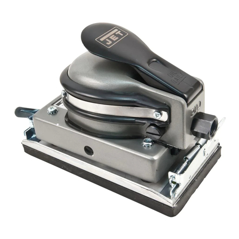
Jet JSB-10H User manual

OWNER'S MANUAL
JSB-10L/H Buffer & Sander
WMH TOOL GROUP
Consumer/Light Industrial Products Division
P.O. BOX 1349
Auburn, WA 98071-1349
Ph: 1-800-274-6848
▪
Fax: 1-800-274-6840
E-mail: jet@wmhtoolgroup.com
www.wmhtoolgroup.com M-577110 01/03
Copyright © WMH Tool Group

2
This manual has been prepared for the owner and operators of a JSB-10L/H. Its purpose, aside from
machine operation, is to promote safety through the use of accepted correct operating and maintenance
procedures. Completely read the safety and maintenance instructions before operating or servicing the
machine. To obtain maximum life and efficiency from your buffer/sander, and to aid in using the machine
safely, read this manual thoroughly and follow instructions carefully.
Warranty & Service
The WMH Tool Group warrants every product it sells. If one of our tools needs service or repair, one of
our Authorized Repair Stations located throughout the United States can give you quick service.
In most cases, any one of these WMH Tool Group Repair Stations can authorize warranty repair, assist
you in obtaining parts, or perform routine maintenance and major repair on your JET, Performax, Wilton,
or Powermatic tools.
For the name of an Authorized Repair Station in your area, please call 1-800-274-6848, or visit
www.wmhtoolgroup.com
More Information
Remember, the WMH Tool Group is consistently adding new products to the line. For complete, up-to-
date product information, check with your local WMH Tool Group distributor, or visit
www.wmhtoolgroup.com
WMH Tool Group Warranty
The WMH Tool Group (including Performax, JET, Wilton and Powermatic brands) makes every effort to
assure that its products meet high quality and durability standards and warrants to the original retail
consumer/purchaser of our products that each product be free from defects in materials and workmanship
as follow: 1 YEAR LIMITED WARRANTY ON ALL PRODUCTS UNLESS SPECIFIED OTHERWISE.
This Warranty does not apply to defects due directly or indirectly to misuse, abuse, negligence or
accidents, normal wear-and-tear, repair or alterations outside our facilities, or to a lack of maintenance.
THE WMH TOOL GROUP LIMITS ALL IMPLIED WARRANTIES TO THE PERIOD SPECIFIED ABOVE,
FROM THE DATE THE PRODUCT WAS PURCHASED AT RETAIL. EXCEPT AS STATED HEREIN,
ANY IMPLIED WARRANTIES OR MERCHANTIBILITY AND FITNESS ARE EXCLUDED. SOME
STATES DO NOT ALLOW LIMITATIONS ON HOW LONG THE IMPLIED WARRANTY LASTS, SO THE
ABOVE LIMITATION MAY NOT APPLY TO YOU. THE WMH TOOL GROUP SHALL IN NO EVENT BE
LIABLE FOR DEATH, INJURIES TO PERSONS OR PROPERTY, OR FOR INCIDENTAL,
CONTINGENT, SPECIAL, OR CONSEQUENTIAL DAMAGES ARISING FROM THE USE OF OUR
PRODUCTS. SOME STATES DO NOT ALLOW THE EXLUSION OR LIMITATION OF INCIDENTAL OR
CONSEQUENTIAL DAMAGES, SO THE ABOVE LIMITATION OR EXCLUSION MAY NOT APPLY TO
YOU.
To take advantage of this warranty, the product or part must be returned for examination, postage
prepaid, to an Authorized Repair Station designated by our office. Proof of purchase date and an
explanation of the complaint must accompany the merchandise. If our inspection discloses a defect, we
will either repair or replace the product, or refund the purchase price if we cannot readily and quickly
provide a repair or replacement, if you are willing to accept a refund. We will return repaired product or
replacement at WMH Tool Group’s expense, but if it is determined there is no defect, or that the defect
resulted from causes not within the scope of WMH Tool Group’s warranty, then the user must bear the
cost of storing and returning the product. This warranty gives you specific legal rights; you may also have
other rights which vary from state to state.
The WMH Tool Group sells through distributors only. Members of the WMH Tool Group reserve the right
to effect at any time, without prior notice, those alterations to parts, fittings, and accessory equipment
which they may deem necessary for any reason whatsoever.

3
WARNING
1. Read and understand the entire owner’s manual before attempting assembly or operation.
2. This buffer/sander is designed and intended for use by properly trained and experienced
personnel only. If you are not familiar with the proper and safe operation of a buffer/sander,
do not use until proper training and knowledge have been obtained.
3. Always wear approved safety glasses/face shields while using this machine.
4. Make certain the machine is properly grounded.
5. Before operating the machine, remove tie, rings, watches, other jewelry, and roll up sleeves above
the elbows. Remove all loose clothing and confine long hair. Do not wear gloves.
6. Keep the floor around the machine clean and free of scrap material, oil and grease.
7. Keep machine guards in place at all times when the machine is in use. If removed for maintenance
purposes, use extreme caution and replace the guards immediately.
8. Do not over reach. Maintain a balanced stance at all times so that you do not fall or lean against
blades or other moving parts.
9. Make all machine adjustments or maintenance with the machine unplugged from the power source.
10. Use the right tool. Don't force a tool or attachment to do a job that it was not designed for.
11. Replace warning labels if they become obscured or removed.
12. Make certain the switch is in the OFF position before connecting the machine to the power supply.
13. Give your work undivided attention. Looking around, carrying on a conversation, and "horse-play" are
careless acts that can result in serious injury.
14. Keep visitors a safe distance from the work area.
15. Use recommended accessories; improper accessories may be hazardous.
16. Read and understand warnings posted on the machine and in this manual.
17. Failure to comply with all of these warnings may cause serious injury.
18. Some dust created by power sanding, sawing, grinding, drilling and other construction activities
contains chemicals known to cause cancer, birth defects or other reproductive harm. Some
examples of these chemicals are:
• Lead from lead based paint
• crystalline silica from bricks and cement and other masonry products, and
• arsenic and chromium from chemically-treated lumber.
19. Your risk from those exposures varies, depending on how often you do this type of work. To reduce
your exposure to these chemicals: work in a well ventilated area, and work with approved safety
equipment, such as those dust masks that are specifically designed to filter out microscopic particles
20. Do not operate tool while under the influence of drugs, alcohol or any medication.
21. Provide for adequate surrounding work space and overhead non-glare lighting.
22. Use only JET factory authorized replacement parts and accessories; otherwise the warranty and
guarantee are null and void.
23. Do not use this JET buffer/sander for other than its intended use. If used for other purposes, JET
disclaims any real or implied warranty and holds itself harmless from any injury that may result from
that use.
24. Make sure buffer/sander is secured firmly to a bench or stand before use.
25. Do not use grinding wheels on this machine. It is strictly designed for buffing and sanding only.
26. Do not allow your hands to come into contact with sanding drums or buffing wheels during operation.
27. Never buff or sand by placing the workpiece on top of the wheel. The wheel may kick the workpiece
toward the operator. Always buff on the downward part of the wheel.

4
Grounding Instructions
Caution: This tool must be grounded while in use to protect the operator from electric shock.
In the event of a malfunction or breakdown, grounding provides a path of least resistance for electric
current to reduce the risk of electric shock. This tool is equipped with an electric cord having an
equipment-grounding conductor and a grounding plug. The plug must be plugged into a matching outlet
that is properly installed and grounded in accordance with all local codes and ordinances.
Do not modify the plug provided. If it will not fit the outlet, have the proper outlet installed by a qualified
electrician.
Improper connection of the equipment-grounding conductor can result in a risk of electric shock. The
conductor, with insulation having an outer surface that is green with or without yellow stripes, is the
equipment-grounding conductor. If repair or replacement of the electric cord or plug is necessary, do not
connect the equipment-grounding conductor to a live terminal.
Check with a qualified electrician or service personnel if the grounding instructions are not completely
understood, or if in doubt as to whether the tool is properly grounded. Use only three wire extension
cords that have three-prong grounding plugs and three-pole receptacles that accept the tool’s plug.
Repair or replace a damaged or worn cord immediately.
115 Volt Operation
As received from the factory, your buffer/sander is ready to run at 115 volt operation. This buffer/sander,
when wired for 115 volt, is intended for use on a circuit that has an outlet and a plug that looks like the
one illustrated in (A). A temporary adapter, which looks like the adapter as illustrated in (B), may be used
to connect this plug to a two-pole receptacle, as shown in (B) if a properly grounded outlet is not
available. The temporary adapter should only be used until a properly grounded outlet can be installed
by a qualified electrician. This adapter is not applicable in Canada. The green colored rigid ear, lug,
or tab, extending from the adapter, must be connected to a permanent ground such as a properly
grounded outlet box, as shown in (B).

5
Introduction
The JET JSB-10 buffer/sander you have purchased is a high quality tool that will give you years of
superior service. You will get maximum performance and enjoyment from your new buffer/sander if you
would take a few moments now to review the entire manual before beginning assembly and operation.
The JET JSB-10, as well as all JET products, is backed by a nationwide network of authorized distributors
and/or service centers. Please contact your nearest distributor should you require parts or service. Parts
are also available directly from JET by calling 1-800-274-6848.
Table of Contents
Warranty..................................................................................................................................................2
Warnings.................................................................................................................................................3
Grounding Instructions.............................................................................................................................4
115V Operation .......................................................................................................................................4
Introduction..............................................................................................................................................5
Table of Contents....................................................................................................................................5
Specifications ..........................................................................................................................................5
Contents of the Shipping Container..........................................................................................................6
Unpacking and Cleanup...........................................................................................................................6
Assembly..............................................................................................................................................6-7
Buffing and Polishing...............................................................................................................................7
Drum Sanding..........................................................................................................................................7
Sanding and Buffing Accessories.............................................................................................................7
Part’s Breakdown and Part’s List...........................................................................................................8-9
Wiring Diagram......................................................................................................................................10
Specifications JSB-10L JSB-10H
Stock Number..............................................708110 ..................................................................... 708112
Speeds (RPM).............................................1725 .............................................................................3450
Motor...........................................................1HP, 115/230V, 1Ph .............................1HP, 115/230V, 1Ph
....................................................................115V/230V, Prewired 115V.......115V/230V, Prewired 115V
Overall Dimensions (H x W x D in.)..............11-3/4” x 37” x 7-1/2”............................ 11-3/4” x 37” x 7-1/2”
Net Weight (approx.)....................................102 Lbs....................................................................102 Lbs.
Shipping Weight (approx.)............................109 Lbs....................................................................109 Lbs.
The specifications in this manual are given as general information and are not binding. WMH Tool Group
reserves the right to effect, at any time and without prior notice, changes or alterations to parts, fittings,
and accessory equipment deemed necessary for any reason whatsoever.
6
WARNING
Read and understand the entire contents of
this manual before attempting assembly or
operation!
Failure to comply may cause serious injury!
Contents of the Shipping Container
1. Buffer/Sander
4. Flange Washers 5/8" ID
4. Flange Washers 1” ID
2. Bushing 1/4”
2. Bushing 3/8”
2. Bushing 1/2”
2. Bushing 1”
2. Bushing 1-3/4”
2. Bushing 3”
2. Bushing 4”
2. Flat Washer ID 5/8” x OD 1-1/4”
1. Hex Nut 5/8” (right hand threads)
1. Hex Nut 5/8” (left hand threads)
1. Owner’s Manual & Warranty Card
Unpacking and Clean-Up
1. Remove product from shipping container.
Do not discard any shipping material until
the buffer/sander is set up and running
properly.
2. Clean all rust protected surfaces with a
cleaner degreaser.
Assembly
WARNING
Always unplug the sander / buffer before
performing any maintenance, or assembly.
Failure to comply may cause serious injury!
1. Mount buffer/sander to a solid workbench, or
stand.
2. Use the correct bushing (A, Fig. 1)
combination to go along with the buffing, or
sanding accessory (B, Fig. 1).
3. Secure bushing and buffing/sander
assembly into place using the flat washer
(C, Fig. 1) and hex nut (D, Fig. 1). Note:
threads on the left end of shaft are for the
hex nut with left hand threads. Threads on
the right end of shaft are typical right hand
threads.
4. There is a flat spot (E, Fig. 1) on the shaft to
hold in place while tightening, or loosening
the hex nut.

7
5. Use the flange washers (F, Fig. 2) on either
side of soft accessories such as, buffing
wheels (G, Fig. 2). Note: If the accessory
has a 5/8" ID mount on the threaded section
of the shaft along with the 5/8” ID flanges. If
the accessory has a 1” ID mount on the
main portion of the shaft using the 1” ID
flanges.
6. Turn the buffer / sander on and off by using
toggle switch (H, Fig. 3).
Buffing & Polishing
WARNING
Never sand or buff with the workpiece on top
of the wheel. The workpiece may be catch
the wheel and be thrown at the operator.
Always process the workpiece near the
bottom of the wheel!
1. Select the appropriate stick of polishing
compound for your application and apply to
the rotating face of the wheel.
2. Start the buffer and with both hands firmly
grasp the item to be polished. Lightly and
evenly move the workpiece back and forth
on the buffing wheel.
Drum Sanding
1. Slide sanding sleeve onto the drum. Ensure
that the arrows on the inside of the sleeve
point in the direction of the drum rotation.
2. Inflate the drum using a hand pump. Some
sanding applications may require more, or
less air in the drum. The maximum air
pressure is 10 psi. Do not over inflate!
3. Flip the switch up to turn the machine on
and firmly grasp the workpiece to be
sanded.
4. With light and even pressure against the
direction of rotation, move the workpiece
back and forth on the sanding drum. Sand
in the direction of the wood grain.
Sanding and Buffing Accessories
Jet offers a wide variety of sanding, buffing and
polishing accessories for use with this machine.
Visit www.wmhtoolgroup.com and go to JET
Woodworking Accessories to view the options.
Then visit your local JET Distributor to make a
purchase.

8
Breakdown for the JSB-10 Sanding/Buffing Machine

9
Parts List for the JSB-10 Sanding/Buffing Machine
Index Part
No. No. Description Size Qty.
1..........JSB10-1....................................Motor Housing....................................... ...................................1
2..........JSB10-2....................................Base ..................................................... ...................................1
3..........JSB10L-3..................................Shaft..................................................... 1725 rpm....................1
............JSB10H-3 .................................Shaft ..................................................... 3450 rpm....................1
4..........JSB10L-4..................................Stator.................................................... 1725 rpm....................1
............JSB10H-4 .................................Stator.................................................... 3450 rpm....................1
5..........JSB10L-5..................................Centrifugal Switch w/Socket .................. 1725 rpm....................1
............JSB10H-5 .................................Centrifugal Switch w/Socket.................. 3450 rpm....................1
6..........JSB10-6....................................Pan Head Screw................................... 3/16” x 3/8”.................2
7..........BB-6206ZZ................................Ball Bearing........................................... 6206ZZ.......................2
8..........JSB10-8....................................Plastic Fan............................................ ...................................1
9..........JSB10-9....................................Cover.................................................... ...................................2
10........TS-0720071..............................Lock Washer......................................... 1/4”.............................8
11........TS-081F062..............................Pan Head Screw................................... 1/4” x 1”......................8
12........JSB10-12..................................Rubber Ring.......................................... ...................................1
13........JSB10-13..................................Hex Nut................................................. 5/8” (RH).....................1
14........JSB10-14..................................Hex Nut................................................. 5/8” (LH).....................1
15........JSB10-15..................................Starting Capacitor.................................. 300MFD, 125VAC.......1
16........JSB10-16..................................Capacitor Cover.................................... ...................................1
17........JSB10-17..................................Fixture................................................... ...................................1
18........JSB10-18..................................Pan Head Screw................................... 3/16” x 1/4”.................2
19........JSB10-19..................................Terminal................................................ ...................................1
20........TS-0733041..............................Tooth Washer ....................................... 1/4".............................1
21........JSB10-21..................................Copper Washer..................................... M5..............................1
22........JSB10-18..................................Pan Head Screw................................... 3/16” x 1/4”.................1
23........JSB10-23..................................Switch Plate.......................................... CSA type....................1
24........JSB10-24..................................Toggle Switch w/Dust Cover.................. ...................................1
25........JSB10-25..................................Wire Clamp........................................... ...................................1
26........JSB10-26..................................Wire Plate............................................. ...................................1
27........JSB10-27..................................Power Cord........................................... ...................................1
28........JSB10-28..................................Base Plate............................................. ...................................1
29........JSB10-29..................................Rubber Pad........................................... ...................................4
30........JSB10-30A................................Flange Washer...................................... 5/8” ID ........................4
............JSB10-30B................................Flange Washer...................................... 1” ID...........................4
31........JSB10-31..................................Bushing................................................. 1/4”.............................2
32........JSB10-32..................................Bushing................................................. 3/8”.............................2
33........JSB10-33..................................Bushing................................................. 1/2”.............................2
34........JSB10-34..................................Bushing................................................. 1”................................2
35........JSB10-35..................................Bushing................................................. 1-3/4”..........................2
36........JSB10-36..................................Bushing................................................. 3”................................2
37........JSB10-37..................................Bushing................................................. 4”................................2
38........JSB10-38..................................Flat Washer........................................... ID 5/8” x OD 1-1/4” .....2
39........JSB10-39..................................Wrench................................................. ...................................2
40........JSB10-40..................................ID Label (not shown) ............................. ...................................1

10
Wiring Diagram for the JSB-10 Sanding/Buffing Machine
This manual suits for next models
1
Table of contents
Other Jet Sander manuals

Jet
Jet JAT-730 505730 Application guide

Jet
Jet JWDS-2244OSC Service manual

Jet
Jet 10 Plus Service manual

Jet
Jet JBOS-5 User manual

Jet
Jet OES-80CS User manual

Jet
Jet 708599 Service manual

Jet
Jet JAT-741 Application guide

Jet
Jet JTM-4VS Service manual

Jet
Jet JSG-96 Service manual

Jet
Jet SandSmart 16-32 Plus User manual
Popular Sander manuals by other brands

Hitachi
Hitachi SB 10V2 Handling instructions

Clarke
Clarke Contractor CROS2 Operating & maintenance instructions

Villager
Villager VLN 382 Original instruction manual

Skil
Skil 7292 owner's manual

EINHELL
EINHELL TE-DW 225 X Original operating instructions

Universal Tool
Universal Tool UT8789-5-336SV operating instructions