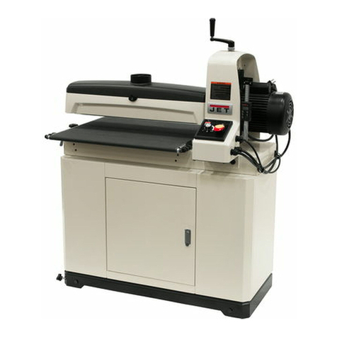
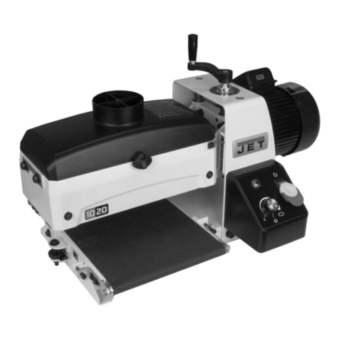
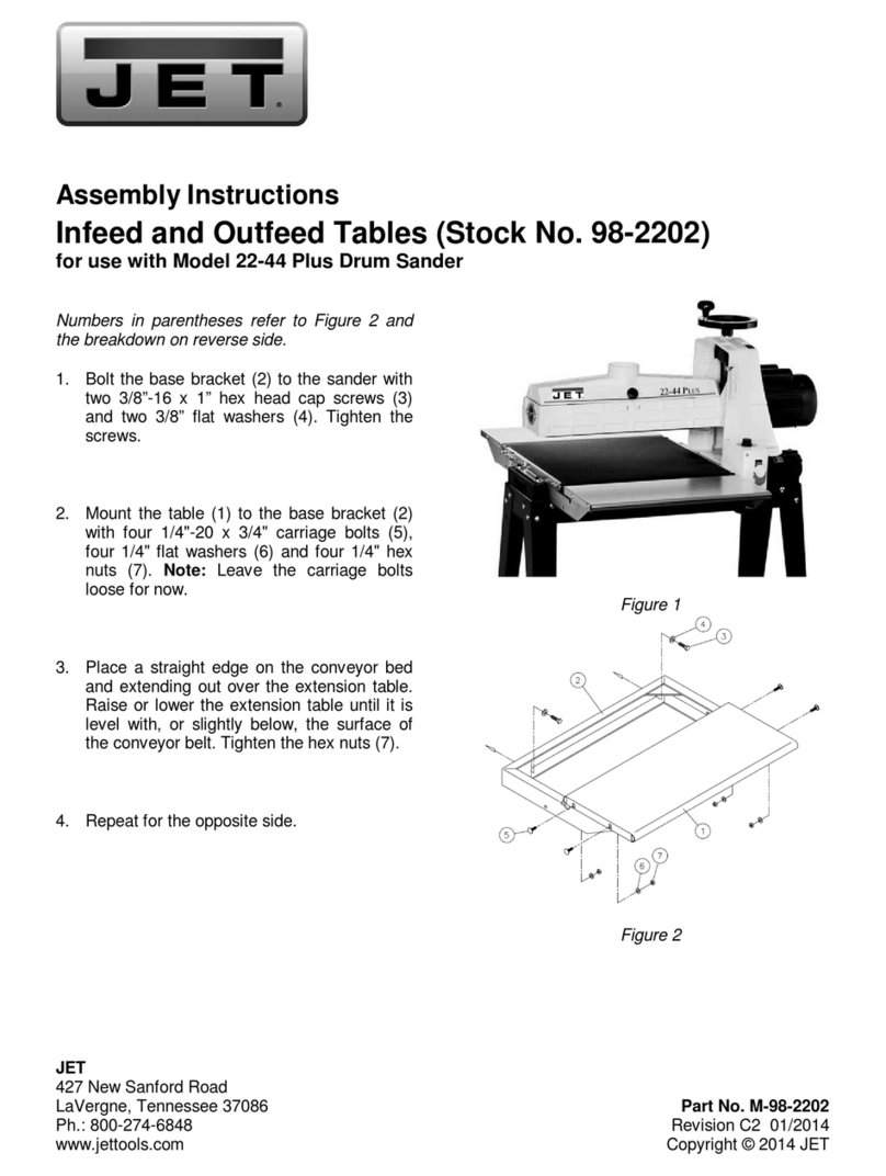
Jet JWDS-1020-M User manual

JWDS‐1020‐M
DrumSander
Zylinderschleifmaschine
Ponceuseàcylindre
Original:
GB
OperatingInstructions
D
Gebrauchsanleitung
F
Moded´emploi
TOOLFRANCESARL
9ruedesPyrénées,F‐91090LISSES,
France
www.jettools.com
M‐723510M2019‐12

2
CE‐ConformityDeclaration
CE‐Konformitätserklärung
DéclarationdeconformitéCE
Product/Produkt/Produit:
Drumsander/Zylinderschleifmaschine/Ponceuseàcylindre
JWDS‐1020‐M
723510M
Brand/Marke/Marque:
JET
Manufacturer/Hersteller/Fabricant:
TOOLFRANCESARL
9RuedesPyrénées,91090LISSES,France
Weherebydeclarethatthisproductcomplieswiththeregulations
Wirerklärenhiermit,dassdiesesProduktderfolgendenRichtlinieentspricht
Parlaprésente,nousdéclaronsqueceproduitcorrespondauxdirectivessuivantes
2006/42/EC
MachineryDirective/Maschinenrichtlinie/DirectiveMachines
2014/30/EU
Electromagneticcompatibility/elektromagnetischeVerträglichkeit/compatibilitéélectromagnétique
designedinconsiderationofthestandards
undentsprechendfolgenderzusätzlicherNormenentwickeltwurde
etétédéveloppédanslerespectdesnormescomplémentairessuivantes
ENISO12100:2010
EN60204‐1:2006+A1:2009
EN61000‐6‐2:2005
EN61000‐6‐4:2007+A1:2011
ResponsiblefortheDocumentation/Dokumentations‐Verantwortung/ResponsabilitédeDocumentation:
HeadProduct‐Mgmt./LeiterProdukt‐Mgmt./Resp.deGestionsProduits
TOOLFRANCESARL
2019‐12‐17ChristopheSAINTSULPICE,GeneralManager
TOOLFRANCESARL
9RuedesPyrénées,91090LISSES,France

3
GB‐ENGLISH
OperatingInstructions
DearCustomer,
ManythanksfortheconfidenceyouhaveshowninuswiththepurchaseofyournewJET‐machine.Thismanualhas
been prepared for the owner and operators of a JET JWDS‐1020‐M drum sander to promote safety during
installation,operationandmaintenanceprocedures.Pleasereadandunderstandtheinformationcontainedinthese
operatinginstructionsandtheaccompanyingdocuments.Toobtainmaximumlifeandefficiencyfromyourmachine,
andtousethemachinesafely,readthismanualthoroughlyandfollowinstructionscarefully.
TableofContents
Section Page
1.Declarationofconformity.............................................................................................................................................4
2.Warranty.......................................................................................................................................................................4
3.Safety...........................................................................................................................................................................4
3.1Authorizeduse.......................................................................................................................................................4
3.2Generalsafetynotes..............................................................................................................................................4
3.3Remaininghazards.................................................................................................................................................5
3.4Labelsandpositions...............................................................................................................................................5
4.0Specifications.............................................................................................................................................................6
5.0FeaturesandTerminology.........................................................................................................................................7
6.0Setupandassembly...................................................................................................................................................7
6.1Shippingcontents..................................................................................................................................................7
6.2Toolsrequiredforassembly..................................................................................................................................7
6.3Handle...................................................................................................................................................................8
6.4Mountingtoworkbench........................................................................................................................................8
6.5Dustcollection.......................................................................................................................................................8
6.6Installingabrasives................................................................................................................................................8
7.0Electricalconnections................................................................................................................................................9
8.0Adjustments...............................................................................................................................................................9
8.1DrumHeightControl.............................................................................................................................................9
8.2Depthscale............................................................................................................................................................9
8.3Conveyorbelttension/tracking.............................................................................................................................9
8.4Inspectingdrumalignment..................................................................................................................................10
8.5Tensionrolleradjustment...................................................................................................................................11
9.0Operations...............................................................................................................................................................11
9.1BasicOperatingProcedure..................................................................................................................................11
9.2Drum&conveyormotoroperation.....................................................................................................................11
9.3Circuitbreakerreset............................................................................................................................................11
9.4Settingdepthofcut.............................................................................................................................................11
9.5Establishingdrumheight.....................................................................................................................................12
9.6Maximumperformancetips................................................................................................................................12
10.0User‐maintenance..................................................................................................................................................13
10.1Cleaningandlubrication....................................................................................................................................13
10.2Drummaintenance............................................................................................................................................13
10.3Conveyorbeltreplacement...............................................................................................................................14
10.4Commutatorbrushinspection...........................................................................................................................14
10.5Additionalservicing...........................................................................................................................................15
11.0Abrasives................................................................................................................................................................15
11.1Selectingdrumabrasives...................................................................................................................................15
11.2Cleaningabrasivestrips.....................................................................................................................................15
11.3Increasingabrasivelife......................................................................................................................................15
11.4Abrasiveselectionguide....................................................................................................................................15
12.0TroubleshootingJWDS‐1020‐MDrumSander.......................................................................................................16

4
1.Declarationofconformity
Onourownresponsibilityweherebydeclarethatthis
productcomplieswiththeregulationslistedonpage
2.Designedinconsiderationwiththestandards.
2.Warranty
TOOLFranceSARLguaranteesthatthesupplied
productisfreefrommaterialdefectsand
manufacturingfaults.
Thiswarrantydoesnotcoveranydefectswhichare
caused,eitherdirectlyorindirectly,byincorrectuse,
carelessness,accidentaldamage,repair,inadequate
maintenanceorcleaningandnormalwearandtear.
Anywarrantydetails(i.e.warrantyperiod)canbe
foundintheGeneralTermsandConditions(GTC)that
areintegralpartofthecontract.
TheseGTCcanbeviewedatthewebsiteofyour
dealerorsenttoyouuponrequest.
TOOLFranceSARLreservestherighttomakechanges
totheproductandaccessoriesatanytime.
3.Safety
3.1Authorizeduse
Thisdrumsanderisdesignedforsandingwoodand
similarmaterialsonly.Sandingofothermaterialsis
notpermittedandmaybecarriedoutinspecificcases
onlyafterconsultingwiththemanufacturer.
Themachineisnotsuitableforwetsanding.
Theproperusealsoincludescompliancewiththe
operatingandmaintenanceinstructionsgiveninthis
manual.
Themachinemustbeoperatedonlybypersons
familiarwithitsoperationandmaintenanceandwho
arefamiliarwithitshazards.
Therequiredminimumagemustbeobserved.
Themachinemustonlybeusedinatechnically
perfectcondition.
Whenworkingonthemachine,allsafetymechanisms
andcoversmustbemounted.
Inadditiontothesafetyrequirementscontainedin
theseoperatinginstructionsandyourcountry’s
applicableregulations,youshouldobservethe
generallyrecognizedtechnicalrulesconcerningthe
operationofwoodworkingmachines.
Anyotheruseexceedsauthorization.
Intheeventofunauthorizeduseofthemachine,the
manufacturerrenouncesallliabilityandthe
responsibilityistransferredexclusivelytothe
operator.
3.2Generalsafetynotes
Woodworkingmachinescanbedangerousifnotused
properly.Thereforetheappropriategeneraltechnical
rulesaswellasthefollowingnotesmustbeobserved.
Readandunderstandtheentireinstructionmanual
beforeattemptingassemblyoroperation.
Keepthisoperatinginstructionclosebythemachine,
protectedfromdirtandhumidity,andpassitovertothe
newownerifyoupartwiththetool.
Nochangestothemachinemaybemade.
Dailyinspectthefunctionandexistenceofthesafety
appliancesbeforeyoustartthemachine.
Donotattemptoperationinthiscase,protectthe
machinebyunpluggingthepowercord.
Beforeoperatingthemachine,removetie,rings,
watches,otherjewellery,androllupsleevesabovethe
elbows.
Removealllooseclothingandconfinelonghair.
Wearsafetyshoes;neverwearleisureshoesorsandals.
Alwaysweartheapprovedworkingoutfit:
‐eyeprotection
‐expiratoryprotection
‐dustprotection
Donotwearlooseclothesandgloveswhileoperating
thismachine.
Installthemachinesothatthereissufficientspacefor
safeoperationandworkpiecehandling.
Keepworkareawelllighted.
Themachineisdesignedtooperateinclosedroomsand
mustbeboltedstableonfirmandlevelledtablesurface
oronthesuppliedcabinetstand.
Makesurethatthepowercorddoesnotimpedework
andcausepeopletotrip.
Keeptheflooraroundthemachinecleanandfreeof
scrapmaterial,oilandgrease.
Stayalert!
Giveyourworkundividedattention.
Usecommonsense.Donotoperatethemachinewhen
youaretired.
Keepanergonomicbodyposition.
Maintainabalancedstanceatalltimes.


5
Donotoperatethemachineundertheinfluenceof
drugs,alcoholoranymedication.Beawarethat
medicationcanchangeyourbehaviour.
Neverreachintothemachinewhileitisoperatingor
runningdown.
Alwaysclosethedrumcoverbeforeyoustartthe
machine.
Keepyourhandsdistanttodrumhousingandconveyor
beltwhenfeedingtheworkpiece.
Keepchildrenandvisitorsasafedistancefromthework
area.
Neverleavearunningmachineunattended.Beforeyou
leavetheworkplaceswitchoffthemachine.
Donotoperatetheelectrictoolnearinflammableliquids
orgases.
Observethefirefightingandfirealertoptions,for
examplethefireextinguisheroperationandplace.
Donotusethemachineinadumpenvironmentanddo
notexposeittorain.
Sandingdustisexplosiveandcanalsorepresentariskto
health.
Alwaysuseasuitabledustextractiondevice.
Beforemachining,removeanynailsandotherforeign
bodiesfromtheworkpiece.
Machineonlystockwhichrestssecurelyonthetable.
Specificationsregardingthemaximumorminimumsize
oftheworkpiecemustbeobserved.
Donotremovechipsandworkpiecepartsuntilthe
machineisatastandstill.
Donotstandonthemachine.
Connectionandrepairworkontheelectricalinstallation
maybecarriedoutbyaqualifiedelectricianonly.
Haveadamagedorwornpowercordreplaced
immediately.
Makeallmachineadjustmentsormaintenancewiththe
machineunpluggedfromthepowersource.
Protecttheenvironment,
disposeofthepackingin
anenvironmentallyfriendlymanner.
Yourappliancecontainsvaluablematerialswhichcan
berecoveredorrecycled.Pleaseleaveitata
specializedinstitution.
Thissymbolindicatesseparatecollectionforelectrical
andelectronicequipmentrequiredundertheWEEE
Directive(Directive2012/19/EC)andiseffectiveonly
withintheEuropeanUnion.
3.3Remaininghazards
Whenusingthemachineaccordingtoregulations
someremaininghazardsmaystillexist.
Themovingsandingsleevecancauseinjury.
Riskofkickback.Theworkpieceiscaughtbythe
movingsandingsleeveandthrownbacktothe
operator.
Thrownworkpiecepartscanleadtoinjury.
Sandingdustandnoisecanbehealthhazards.Besure
towearpersonalprotectiongearsuchassafety
gogglesanddustmask.Useasuitabledustexhaust
system.
Defectiveabrasivescancauseinjuries.
Theuseofincorrectmainssupplyoradamaged
powercordcanleadtoinjuriescausedbyelectricity.
3.4Labelsandpositions
A: Safetywarning
B: Sandingdrum&Conveyorbeltrunningdirection
C: Loosentablelockbeforeadjustingtableparallel
Fig.AFig.B
Fig.C
Note: The figures are general in native and may not
showyourparticularsandermodel.

6
4.0Specifications
Table1
Modelnumber JWDS‐1020‐M
Stocknumber 723510M
MotorandElectricals
Drummotortype inductionmotor
Motorpower 0.75kW(1HP)
Voltage 1~230V,PE,50Hz
ListedFLA(fullloadamps) 3.5A
Motorspeed 1400/min
Startingamps 14A
Runningamps(noload) 1.9A
Runningcapacitor 12uF450VAC
Conveyormotortype totallyenclosedDCmotor
Motorpower 25W
Motorspeed 54/min
On/offswitch magneticswitch
Powertransfer directdrive
Powercable H05RN‐F,3x1.0mm2
Recommendedcircuitsize1 16A
Soundemission(acousticpressurelevelLpA,ENISO11202)268dBidling,70dBinoperation
Capacities
Maximumboardwidth(singlepass) 254mm
Maximumboardwidth(twopasses) 508mm
Maximumboardthickness 76mm
Minimumboardlength 60mm
Minimumboardthickness30.8mm
Mainmaterials
Mainbody aluminiumdiecastingandsteel
Drum extrudedaluminium
Conveyortable steel
Drumheightadjustmenthandle plastic
SandingDrum
Drumdimensions,LxDia 257x127mm
Drumspeed 1400/min
Abrasiveinstalled 80Grit,76mm,alu‐oxide
Drumelevationperonerotationofhandwheel 1.6mm
Conveyor
Conveyorspeed variablewithin0‐3m/min
Conveyortabledimensions 254x381mm
Dustcollection
Dustportoutsidediameter 100mm
Recommendedminimumextractionvolume 560m3/h
Dimensions
Assembleddimensions,LxWxH 682x455x454mm
Shippingdimensions,LxWxH 610x480x440mm
Weights
Netweight(approx.) 33kg
Shippingweight(approx.) 37kg
1Subjecttolocal/nationalelectricalcodes.
2Thespecifiedvaluesareemissionlevelsandarenotnecessarilytobeseenassafeoperatinglevels.Asworkplaceconditions
vary,thisinformationisintendedtoallowtheusertomakeabetterestimationofthehazardsandrisksinvolvedonly.

7
3Useofacarrierorbackerboard(notprovided)isrecommendedforcuts1,5mmorless.Seesection9.4.
L=length,W=width,H=height,Dia=diameter
Thespecificationsinthismanualwerecurrentattimeofpublication,butbecauseofourpolicyofcontinuous
improvement,JETreservestherighttochangespecificationsatanytimeandwithoutpriornotice,withoutincurring
obligations.
5.0FeaturesandTerminology
TheillustrationbelowshowsthemajorcomponentsandfeaturesoftheJWDS‐1020‐MSanders.Thesearereferenced
throughoutthemanualandwillhelptofamiliarizeyouwiththeoperationandfunctionsofthemachine.
Figure5‐1:featuresandterminology
Readandunderstandthe
entirecontentsofthismanualbefore
attemptingset‐uporoperation.Failureto
complymaycauseseriousinjury.
6.0Setupandassembly
Openboxandcheckforshippingdamage.Reportany
damageimmediatelytoyourdistributorandshipping
agent.Anymissingpartsshouldbereportedtoyour
distributor.Donotdiscardshippingmaterialuntilthe
DrumSanderisassembledandrunningsatisfactorily.
6.1Shippingcontents
1 Sanderwithconveyortable
1 Handle
4 Foampads
1 Operatingmanual
1 Sparepartslist
6.2Toolsrequiredforassembly
3mmhexwrench
Straight edge (such as straight steel bar or carefully
jointedboard)
Additional tools may be needed for adjustments or
mountingthesandertoaworkbench.

8
6.3Handle
Install handle onto elevating screw, aligning flat in
handleshaftwithflatonelevatingscrew.Tightenset
screwwith3mmhexwrenchtosecurehandle.
Figure6‐1:installinghandle
6.4Mountingtoworkbench
Thesandershouldbeboltedtoaworkbenchortable
toavoidanytendencytocreeporslideduring
sanding operations. Use appropriate fasteners (not
provided)throughthe4slotsinthemachinebase.
6.5Dustcollection
Dustcollectionismandatoryforasafework
environment and extended abrasive life. The JWDS‐
1020isequippedwitha100mmdustcollectionport.
Securea100mmdustcollectionhose(notprovided)
totheportwithahoseclamp(seeFigure6‐2).
Connect to a high volume dust collector, minimum
560m3/h.
Figure6‐2(hoseandclampnotincluded)
6.6Installingabrasives
Properattachmentoftheabrasivestriptothedrum
iscriticaltoachievingtopperformancefromyour
drumsander.
An80‐grit,76mmwideabrasivestrip ispre‐installed
onthedrum.
(TIP:Ifyouareusinganafter‐marketabrasive,usea
new JET‐supplied abrasive as a template to quickly
cutanewstrip.
Figure6‐3:abrasivetrimming
1. Rotatehoodlatchcounterclockwisetoopen.
2. Press fastener lever (Figure 6‐4) on outboard
(left)endofdrum,andinserttaperedendof
abrasivethroughslitinfastener,asshown.Align
taperededgeofabrasivestripwithleftedgeof
drum.Insertenoughstripsothattherightedge
alignswiththereferencenotch;thiswillensure
the proper length of strip to be secured at the
oppositeendofthedrum.
Figure6‐4
3. Releasefastenerlevertosecureendofstrip.
4. Begin wrapping abrasive around drum. The
tapered edge of strip end should follow as
closelyaspossibletoedgeofdrum.
5. Continue to wrap abrasive in spiral fashion by
rotating drum with one hand and guiding strip
withtheother.SeeFigure6‐5.
Successive windings of strip must not have any
overlap. They should be flush with previous
windingsorwithaslightgapbetween.
Figure6‐5

9
6. Press inboard take‐up lever (Figure 6‐6) and
insert trailing end of strip as far as it will go. If
necessary,trimtaperedendofabrasivestrip.
7. Releaseinboardtake‐uplevertosecurestrip.
All abrasive strips will stretch over time as they are
used, and may stretch enough to allow the take‐up
lever to reach its lowest position so that it cannot
maintaintensiononthestrip.Ifthisoccurs,follow
theaboveprocedurestoresetthetake‐uplever.
Figure6‐6
7.0Electricalconnections
Allelectricalconnectionsmustbe
donebyaqualifiedelectricianincompliancewithall
local codes and ordinances. Failure to comply may
resultinseriousinjury.
The JWDS‐1020 Sander is rated at 230‐Volt power
only.Thesandercomeswithaplugdesignedforuse
onacircuitwithagrounded outlet. Before
connectingtopowersource,besureswitchisinoff
position.
Itisrecommendedthatthesanderbeconnectedtoa
dedicated16ampcircuitwithcircuitbreakerorfuse.
Ifconnectedtoacircuitprotectedbyfuses,usetime
delayfusemarked“D”.Localcodestakeprecedence
overrecommendations.
8.0Adjustments
8.1DrumHeightControl
Drum height and depth of cut are controlled by the
height adjustment handle (see Figure 6‐1). Rotating
handle clockwise lowers drum, counter clockwise
raises it. One revolution of handle will move drum
approximately1.6mm(or1/4turn=approx.0.4mm),
asshownonthelabelbelowhandle.
8.2Depthscale
The depth scale indicates distance between bottom
of sanding drum and top of conveyor belt.
Adjustmentisperformedby“zeroing”thescale.
1. Unplugsanderfrompowersource.
2. Withanabrasivestripondrum,lowerdrumto
where it touches top of conveyor belt. Note:
Makesuredrumcontactsbelt,notjustthefeed
rollers.
3. At this drum position, the (top edge of) depth
scale pointer should align with zero mark on
scale. If it does not, loosen screw (Figure 8‐1)
andshiftpointertoalignwithzero.
4. Retightenscrew.
Note:Dependingondesiredaccuracy,youmayneed
to repeat this process when installing different
abrasivegrits.
Figure8‐1:depthscaleadjustment
8.3Conveyorbelttensionandtracking
Conveyorbelttension adjustmentmaybenecessary
during the break‐in period to compensate for belt
stretching,andalsoafterlong‐termuse.
8.3.1Belttensionadjustment
NOTE:Insufficientbelttensionwillcauseslippageof
conveyor belt on drive roller during sanding
operation.Theconveyorbeltistoolooseifitcanbe
stopped by hand pressure applied directly to top of
moving conveyor belt. Excessive belt tension can
result in bent rollers, bent brackets, and/or
prematurewearingofbushingsorconveyorbelt.
Toadjustconveyorbelttension:
1. Slightlyloosenfourscrews(A,Figure8‐2)on
infeed side of conveyor, with 4mm hex wrench
(twoscrewsoneachside).
2. Turntake‐upscrew(B,Figure8‐2)with5mmhex
wrench. Do this on both sidesofconveyorto
obtain approximately equal tension on both
sidesofsandingbeltwhentaut.
3. Tightenfourscrews(A,Figure8‐2).
4. Check conveyor belt tracking before operating
machine.Proceedtosect.8.3.2.

10
Figure8‐2:belttensionadjustment
8.3.2Trackingadjustment
Abelttrackscorrectlywhenitmovescentrallyonthe
conveyor rollers without drifting to either side.
Trackingadjustmentsaremadewhileconveyorbeltis
running.
1. Make sure proper belt tension has been
achieved(sect.8.3.1).
2. Turn on conveyor and set to maximum speed.
Watchfortendencyofconveyorbelttodriftto
onesideofconveyor.
3. Ifconveyordrifts,slightlyloosentwoscrews(A,
Figure8‐2)and turntake‐upscrew (B,Figure8‐
2)ononesideofconveyorasneeded.
Note: Adjust take‐up screw only 1/4‐turn at a
time.Allowtimeforbelttoreacttoadjustments
beforeproceedingfurther.
4. Whenadjustmentissatisfactory,tightentwo
screws(A,Figure8‐2).
Avoidover‐adjusting,asthismayaffectbelttension.
Iftensionisaffected,ifmaybecomenecessarytouse
both take‐up screws to accomplish tensioning and
tracking.
8.4Inspectingdrumalignment
Thesandingdrummustbeparalleltoconveyortable
for proper machine operation. The sanding drum
comes pre‐aligned from the manufacturer. If a
problem with drum alignment should occur, follow
theinstructionsbelow.
First, inspect the alignment with a gauge of some
kind. The following procedure uses a steel straight‐
edgeasagauge.
1. Unplugsanderfrompowersource.
2. Openhoodandremoveabrasivestripfrom
drum.
3. Positiongauge(F,Figure8‐3)betweendrumand
conveyortableatoutboardsideofdrum.
Figure8‐3:drumalignment
4. Withhoodopen,lowersandingdrumwhile
slowlyrotatingdrumbyhand,untildrumlightly
contacts gauge. NOTE: Make sure gauge is
contacted by the drum, not just the tension
rollers.Makeanoteofthemeasurementonthe
sander’sdepthscale.
5. Removegaugeandplaceunderdrumatinboard
side.
6. Ifdrumdoesnotcontactgaugeequallyonboth
endsofdrum,alignmentisneeded.
8.4.1Performingdrumalignment
Toalignconveyortablewithdrum:
1. Loosenbothtablelockingscrews(C,Figure 8‐3)
with5mmhexwrench.
Loosen both table locking
screwsbeforeadjustingdrumalignment.
Toe.g.raiseoutboard end of table, loosen lock
nut (E, Figure 8‐3) and rotate knurled nut (D,
Figure8‐3)clockwise(+).
2. Verifysettingusingthegauge.Makefurther
adjustmentsusingknurlednutasneeded.
3. Retightentablelockscrews(C).
8.4.2Fine‐tuningdrumalignment
Note:Thisisanoperationaltestforsandingboards
wider than the drum. Perform this procedure only
after you have become familiar with sander
operation.
Whensandingboardswiderthanthedrum,table
alignment is critical and table must be adjusted
exactly level to slightly lower on the outboard end.
This will prevent any ridges from developing in the
stock.Alwayscheckthisonapieceofscrapwood,as
follows,beforesandingtheworkpiece.
1. Run a piece of scrap wood approximately
150mmwideby400mmlongthroughthesander
sidewayssothatendofboardextendspast
outboard side of drum, so that approximately
50%ofthesurfaceismachined.
2. Without changing drum height, rotate board
180°andsandthesameside.

11
3. If a ridge is visible where the drum overlaps,
lowertableatoutboardend(seesect.8.4.1).
4. Repeatthisprocessuntiltheridgeis eliminated
andentireboardissanded.
Note: When sanding narrow stock (less than
254mm),returnconveyortabletoparallelposition.
8.5Tensionrolleradjustment
The infeed and outfeed rollers are tensioned to
provide downward pressure on the workpiece to
prevent slippage on the feed conveyor. Tension
rollers have been set by the manufacturer, but
should be inspected and may require adjustment as
thesanderreceivesuse.
Improperly adjusted tension
rollers(i.e.thosesettoohigh,renderingthemnon‐
functional) could allow kickback of pieces being
sanded.
Tensionrollerpressuremaybeincreasedor
decreasedbyturningthescrewsonthetensionroller
brackets(Figure8‐4)ateachendofdrum.
Figure8‐4:tensionadjustmentscrews
Toomuchtensionrollerpressurecanresultina
“snipe” mark, which is a visible line running across
the width of the board and located approximately
55mmfromendofboard.
If snipe occurs on the leading end of board, adjust
outfeedtensionroller.Ifthe snipeoccursontrailing
endofboard,adjustinfeedtensionroller.
9.0Operations
Beforeusingyourdrumsander,reviewtheprevious
sections on initial set‐up and adjustment. Before
operating,makesureanabrasivestripismounted
andaproperdustcollectionsystemisconnected.
9.1BasicOperatingProcedure
1. Establishdepthofcut.
2. Startdustcollectionsystem.
3. Start sanding drum (with control panel switch,
Figure9‐1).
4. Startconveyorandselectfeedrate(withcontrol
paneldial,Figure9‐1).
5. Feedstockthroughmachine.
To feed stock through the sander, rest and hold
board to be sanded on conveyor belt, allowing
conveyorbelttocarryboardintodrum.Oncestockis
halfwaythrough, reposition yourself tooutfeedside
ofmachinetoreceiveandcontrolboardasitexits.
Board will be forced down
againstconveyortableasitbeginsfeeding,causing
pinchinghazard.Keepfingersaway.
Do not open drum hood until
drumcomestoacompletestop.
9.2Drum&conveyormotoroperation
1. Connectpowersupplytomachine.
2. Disengageemergencystopbyclockwiseturning
theredbuttonorpullingitup(A,Figure9‐1).
Note: Error Indicator (D) may flash continuously to
remind that the conveyor speed dial is NOT set at
OFF position before starting the operation. The
control system is designed to prevent the conveyor
belt from being activating accidentally. If conveyor
beltmotordoesn’twork,turnthedial(C)toOFFand
re‐dial.
3. TurnontheOn/Offswitch(B)tostartdrum
motor.
4. Rotateconveyorspeeddial(C)clockwisetostart
andincreasespeedofconveyor.
Figure9‐1:controlpanel
9.3Circuitbreakerreset
This sander is equipped with drum motor overload
protection.Whenthecircuittripsbecauseof
overload,allowaperiodoftimeforthemotortocool
downandthenrestartthemachine.
9.4Settingdepthofcut
Adjusting the drum sander for proper contact
betweenabrasiveandstockdeterminesthedepthof
cut.Thedepthofcutiscontrolledbytheheight
adjustmenthandle.

12
Itmaytakeexperimentationtodetermineproper
depthofcut,giventhevariablesofabrasivegrit,type
ofwoodandfeedrate.Forbestresults,usescrap
wood to practice sanding and to develop skill and
familiaritywiththemachinebeforedoingfinishwork.
A combination of several variables will determine
properdepthofcuttouse,includingthefollowing:
1. Abrasivetypeandgritsize.
2. Widthofpiecebeingprocessed.
3. Hardnessofpiece.
4. Feedrateofconveyorbelt.
NOTE:Theuseofacarrierorbackerboard(not
provided), is recommended for cuts 1,5mm or less.
Thisisaflatboard,usuallyofwoodorMDF,slightly
larger than the workpiece and of even thickness,
placedbeneaththeworkpieceasitisfedthroughthe
sander.Theworkpiecemaybeattachedtothecarrier
withrubbercement,carpenter’stapeorsomeother
easilyremovableadhesive.Someoperatorsusea
rubber or textured surface on the carrier to help
stabilizetheworkpiecebysimplefriction.
9.5Establishingdrumheight
A good rule of thumb when sanding with grits finer
than80:
1. To establish drum height, position stock under
thedrum.DoNOTstartthedrum.
2. Lowerdrumtothestockthickness,makingsure
drum can still be rotated by hand while just
contactingstock.
Donotstartdrumwhilein
contactwithstock.
3. Withoutchangingdrumheight,turnonconveyor
and run the stock out from under the drum.
Startsandingdrumandsandstockatthatsame
position.
4. With the drum operating, feed stock under the
drum from the infeed side and against the
rotationofthedrum.Alwaysmaintaincontrolof
thestocktoavoidkickbackand/orslippage.
NOTE:Ifmotorheatsupduringoperation,depth
ofcutmaybetoogreatforsizeofgritand/or
feedratemaybetoofast.
Forsandingwithgritscoarserthan80,youcanlower
thedrumslightly.
Always maintain control of stock. Through practice
youwilllearntheproperdepthofcutconsideringthe
variablesabove.
A faster feed rate allows faster sanding but fewer
revolutionsofthedrumperinchofsanding.Aslower
feedrateprovidesmorerevolutionsofthedrumper
inch of sanding to allow a greater depth of cut and
smoothsanding.
Beginexperimentingwiththefeedratesetatabout
40%to50%ofmaximum.Thebestfeedratewill
depend on a number of factors, including type of
stock, grit and depth of cut used, and whether the
stockisfeddirectlyinlinewiththeconveyortableor
atanangle.Ifthedrummotorisluggingdown,if
conveyor belt is slipping, or if you observe a ripple
effectonthestock,slowthefeedrate.Ifthefinishis
smoothandthemachineisnotoverworking,youcan
experimentusingafasterfeedrate.
Alsotryafasterfeedrateorlessdepthofcutifthe
stock you are working begins to show burn marks.
Withcherry,hardmapleorotherhardwoods,usinga
shallowerdepthofcutandafasterfeedratewillhelp
minimizeburnmarks.Slightlyanglingthestockasitis
fed into the machine will also help prevent burning
thestock.
Because of the wide range of variables, it is
important to experiment with your specific
conditions and make adjustments to achieve the
optimumfeedrate.Ifproblemsoccur,firstcheckand
adjust the feed rate, referring to sect. 12.0,
Troubleshooting.
9.6Maximumperformancetips
The versatility designed into the JWDS‐series drum
sanderallowsittobeusedforavarietyoftasksthat
willboostreturnonyourinvestment.Forexample,it
will speed up fine sanding work often done with
slower, dust‐generating hand sanders, and will
achieve fine thickness adjustments not possible on
somesanders.Itcanbeusedtosurfacefigured
woods–bird’seyeorcurlymaple,forexample–
whichcanbedamagediffedthroughaplaner.
Learninghowtouseitsadjustmentsandcontrolswill
allow you to fine‐tune the machine for maximum
results. The best results come from experimenting
with different abrasive grits and machine
adjustmentstofitthejobathand.Followingisalist
ofusefultipswhichcanhelpyouimprove
performanceofyoursander.
9.6.1Dustcollection
When connecting dust collectors, remember that
straight pipe will not restrict airflow as much as
flexibletubing.Y’sandelbowswillrestrictairflowless
than T’s. Also, a hose smaller than 80mm diameter
shouldnotbeused.
9.6.2Multiple‐piecesandingruns
Whenabrasiveplaning(orthicknesssanding)arunof
similar pieces that you want to have the same
thickness,itisbesttodeterminethethicknessofthe
thinnest piece and process all pieces to that same
thicknessinonesession.Beawarethatthesander
will remove cups and crowns in the workpiece;
considerthiswhenmeasuringandprocessingstock
tothesamethickness.
9.6.3Simultaneousmultiplepieces
When sanding multiple pieces simultaneously, make
suretostagger(step)thepiecesacrossthewidthof
the conveyor belt. This provides better contact with

13
the tension rollers. Try to process only multiple
piecesofsimilarthickness.
If there is a significant thickness difference, the
thinnerpiecescanslipontheconveyorbeltiftheydo
notcontactthetensionrollers.Alsonotethatpieces
thicker than 20mm should be longer than the
minimumnormallyrecommendedtopreventtipping
ofthestock.
9.6.4Edgesanding
When edge sanding, the sander will mimic the
opposite edge of the stock which is lying on the
conveyorbelt.Becauseofthis,itisimportantforthe
stockedgetohavebeenrippedattheproperangle
to the face before the sanding process. When edge
sanding stock that is less than 3/4” wide or more
than2”high,itisgoodproceduretostackandclamp
several pieces together to prevent them from
slippingortippingontheconveyorbelt.
9.6.5Sandingimperfectstock
When sanding stock with a cup or crown, place the
crownup.Thiswillstabilizethestocktohelpprevent
tipping or rocking during sanding. After the crown
hasbeenremovedandthetopisflat,turnthestock
over and sand the opposite side. To avoid personal
injury,takespecialcarewhensandingstockthatis
twisted,bowed,orotherwisevariesinthicknessfrom
end to end. If possible, support such stock as it is
beingsandedtokeepitfromslippingortipping.Use
extra roller stands, help from another person, or
hand pressure on the stock, to minimize potentially
hazardoussituations.
9.6.6Faceframesandraisedpaneldoors
Itisveryimportanttohavetheproperabrasive
contact when doing this type of sanding. If the
machineissettotakeanexcessivedepthofcut,the
resultcanbeagougeordipasthedrumgoesfrom
sanding the rails at full width to sanding just a few
inchesofwidthonthestiles.Topreventthismake
sure,whenusingabrasivesfinerthan80grit,thatthe
drumisincontactwiththewoodbutcanstillbespun
byhand.Ifthereisroom,anglingthestockonthe
conveyorbeltcanalsohelp.
Slowing the conveyor feed when coming to a rail in
thestockcanhelppreventadiporgouge.Thisallows
theabrasivetoworkthewiderwidthwithlesseffort,
and to achieve better consistency of the finished
surface.
9.6.7Stockfeedingangle
Somepieces,becauseof theirdimensions,willneed
tobefedintothemachineata90°angle
(perpendicular to drum). However, even a slight
offsetangleofstockwillprovideformoreeffective
stockremoval.Theoptimum feeding angle for stock
removalisabout60°.
Angling the workpiece for stock removal provides
other advantages, such as less loading of certain
areasofthedrumduetogluelinesormineralstreaks
inthestock,moreevenwearofabrasivestrips,
potentiallyfasterfeedrates,andlighterloadsonthe
motor.Notethattogetthebestfinalfinish,however,
thestockshouldbefedthroughthemachinesoitwill
besandedinlinewiththegrainofthewoodonthe
finaloneortwopasses.
10.0User‐maintenance
Beforedoingmaintenanceonthe
machine, disconnect it from the electrical supply
(pull out the plug), unless indicated otherwise.
Failuretocomplymaycauseseriousinjury.
10.1Cleaningandlubrication
Forbestresults,makecleaningthesanderaregular
shopprocedure.Allowingexcessbuild‐upofdustand
debriscanadverselyaffectperformancethrough
loading of the abrasives, slippage on the conveyor
table, and/or accumulation of material inside the
drumswhichcanthrowoffthecentreofbalance.
Leavethedustcollectoronwhencleaningdustfrom
the drums. Also brush the conveyor belt after
cleaningoperations.Ifnotcleaned,theconveyorbelt
couldallowstocktoslipduringsandingoperations.
NOTE: Bearings are pre‐sealed and require no
lubrication.
Lubricateelevatingleadscrew(A,Figure10‐1)as
needed.
Cleansandingdustfromabrasivestripandbrush
dustfromconveyorbelt.
Keepguidebarsclean(B,Figure10‐1).
Blowdustfrommotorventsandswitcharea.
Blow dust from inside of sanding drum, which
may cause vibration or offset the centre of
balance.
Check all screws for tightness on parts such as
bearings,conveyortable,andcouplings.
Figure10‐1
10.2Drummaintenance
The drum should not require removal from the
machine under normal circumstances. Should

14
maintenance ever become necessary, the drum has
beendesignedforeasyremovalandreplacement.
1. Unplugsanderfrompowersource.
2. Removetwosocketheadscrews(C,Figure10‐2)
onthebearingblock.
3. Loosentwoscrewsonthecoupling(D,Figure10‐
2).
4. Carefullyslidedrumoutofcouplingandremove
frommachine.
Figure10‐2:drumremoval
10.3Conveyorbeltreplacement
1. Disconnectsanderfrompower.
2. Raisedrumtohighestposition.
3. Loosentwoscrews(E,Figure10‐3)andturn
take‐upscrews(F,Figure10‐3)onbothsidesof
conveyor to relieve belt tension, and slide the
drivenrollerfullyinward.
4. Loosentwotablelockingscrews(G,Figure10‐3).
5. Removelocknut(G,Figure10‐3).
6. Removetwosocketheadscrewsthatattach
conveyortabletobase.
7. Liftupconveyortableandremoveitfrom
machine.Avoidtearingthebeltonanyedges
underneaththeconveyortable.
8. Set conveyor on motor side and slide conveyor
beltoffendofconveyortable.
9. Install new belt and re‐install conveyor table.
Check alignments, and tension and track the
newbelt.
Figure10‐3:conveyorbeltreplacement
Note:Ifconveyorbeltcontinuallytrackstooneside
of the machine, reversing the belt on the conveyor
table may remedy the problem. To make sure the
conveyortableisnottwisted,placealevelonthe
conveyortable.Levelthemachineifneeded.Ifthere
isstillaproblem,proceedwiththestepsbelow:
Step1:Checkconveyordriverolleranddrivenroller
tomakesuretheyareparalleltosurfaceofconveyor
table.Todothis,firstcentreconveyorbeltonthe
conveyor table. Then lay a straight‐edge on the
exposed edge of conveyor table on left (outboard)
side, extending it over the roller. Note distance
betweenrollerandstraightedge.
Step2:NowrepeatStep1onright(inboard)sideof
conveyor. Compare the measurements from side to
side.Iftheyarenotequal,loosenoneofthebrackets
that hold the roller in place. Tip this bracket until
distance between roller and straight‐edge are equal
fromsidetoside,thentightenbracket.
10.4Commutatorbrushinspection
Tomaintainmotorefficiency,inspectthetwocarbon
brushes every two months, or more frequently if
sanderisheavilyused.Stallingor lossofpowermay
beasymptomofworncarbonbrushes.Ifonebrush
iswornout,replacebothatthesametime.
Continued use of damaged or
wornbrushesmayresultindamagetomotor
armature.
1. Unplugsanderfrompowersource.
2. Unscrew and remove cap with flat blade
screwdriver.SeeFigure10‐4.
3. Gentlypryupanedgeofthebrassclip,untilthe
springcausesit todisengagefrom hole.(Notice
orientationofbrushasyouremoveit;itshould
be inserted in the same manner; curvature of
brushwillmatchcurvatureofmotor.)
4. Pull out brush and inspect. Brush should be
replacedifanyofthefollowingarediscovered:
Brushhasworntoabout12mmlong.
Signsofcrumbling,burningorbreaking.
Endofbrushisroughorpitted.
Abnormalcolorationofspring
Brokenleadinspring
Collapsedspring
5. Installnewbrush(orreinstallcurrentbrush)and
gently press it all the way into hole until the
brassclipissecured.
6. Installcap.
7. Repeatforotherbrush.
NOTE:Itisrecommendedthatsanderberunwithout
loadforseveralminutestoseatnewbrushes.

15
Figure10‐4:brushinspection
10.5Additionalservicing
Anyadditionalservicingshouldbeperformedbyan
authorizedservicetechnician.
11.0Abrasives
The abrasive material you choose will have a
substantialeffectontheperformanceofyoursander.
Variations in paper type, weight, coating and
durability all contribute to achieving your desired
finish.
11.1Selectingdrumabrasives
Itisimportanttoselectthepropergritofabrasivefor
the type of sanding being performed to achieve
maximumresults.Aswithanysandingoperation,first
begin sanding with a coarser grit, depending upon
theroughnessofthestockortheamountofstockto
beremoved.Thenprogressivelyworktowardfiner
grits.Thechartbelowshowsthegeneralusesforthe
variousgrits.
The amount of stock to be removed is a major
consideration when choosing the grit grade with
whichtobegin.Grits24,36,50and60areprimarily
designedforstockremoval.Grits24and36will
removethemostmaterialinonepass,whetheryou
aredoingabrasiveplaning,cleaningupgluedpanels,
or flattening stock. Grits from 100 through 220 are
primarily finishing grits designed to remove the
scratchpatternfromthepreviousgritused.Forbest
results, never skip more than one grit grade when
progressingthroughasandingsequence.
For fine work, such as furniture, try not to skip any
gritgradesduringthesandingprocess.
Ingeneral,premiumqualityabrasiveswillproducea
betterfinishwithalessnoticeablescratchpattern.
Note:Gritsthataretoofinecansometimesburnish
the wood and leave a glossy surface which will not
acceptstainsevenly.This will vary bytypeofwood.
Oak, for example, is susceptible to burnishing
becauseofitsopenpores.
11.2Cleaningabrasivestrips
Regularly clean the abrasivestriponthedrumwith
commercially available cleaning sticks, following the
manufacturer’sdirections.Whencleaning,alsobrush
the stick crumbs from the drum while it is still
rotating.
In some cases, heavy loaded areas can be removed
withPlexiglasheldonedgeovertherotatingdrum.
Always wear eye protection
while performing sandpaper cleaning, and take all
precautions to avoid any contact of hands or
clothingwiththerotatingdrum.
Cloth‐backedabrasivescanbecleaned bysoakingin
paintthinnerormineralspiritsfor20minutestoone
hour,thenusingabrushtoremoveanybuild‐up.Dry
theabrasivestripscompletelybeforeusing.Anyused
solvents should be discarded in compliance with
environmentalregulations.
11.3Increasingabrasivelife
Abrasive life can be increased not only by cleaning,
but by removing the abrasive strip from the drum
andreversingit.Todothis,removethestripanduse
whatwasthetrailingendasthestartingendonthe
left(outboard)sideof the drum.Reversingthestrip
will provide a fresh set of cutting edges on the
abrasive.
11.4Abrasiveselectionguide
GritCommonApplication
24,36Abrasiveplaning,surfacingrough‐sawnboards,maximumstockremoval,glueremoval.
50Surfacinganddimensioningboards,truingwarpedboards
60Surfacinganddimensioningboards,truingwarpedboards.
80Lightdimensioning,removalofplanerripples.
100Lightsurfacing.
120Lightsurfacing,minimalstockremoval.
150Finishsanding,minimalstockremoval.
180Finishsandingonly,notforstockremoval.
220Finishsandingonly,notforstockremoval.
Table2

16
12.0TroubleshootingJWDS‐1020‐MDrumSander
Symptom PossibleCause Correction*
Drummotorwon’tstart
whenswitchisactivated.
Noincomingcurrent. Checkconnectionsatplugorcircuitpanel.
Safetykeymissingfromswitch. Installsafetykey.
Lowvoltage. Checkpowerlineforpropervoltage.
Opencircuitinmotororlooseconnection. Inspectallleadconnectionsonmotorforloose
oropenconnections.
Switchmalfunction. Replaceswitch.
Drummotorwillnotstart:
fusesbloworcircuit
breakerstrip.
Shortcircuitinlinecordorplug. Inspectcordorplugfordamagedinsulationand
shortedwires.
Shortcircuitinmotororloose
connections.
Inspectallconnectionsonmotorforlooseor
shortedterminalsorworninsulation.
Incorrectfuseorcircuitbreakerinpower
line.
Installcorrectfuseorcircuitbreaker.
Drummotoroverheats. Aircirculationthroughmotorrestricted. Cleanmotorfanwithcompressedairtorestore
normalaircirculation.
Motoroverloaded,excessfeedrate. Reduceconveyorspeed.
Motoroverloaded,excessdepthofcut. Reducedepthofcut.
Drummotorstalls,
resultinginblownfusesor
trippedcircuit.
Shortcircuitinmotororloose
connections.
Inspectconnectionsonmotorforlooseor
shortedterminalsorworninsulation.
Lowvoltage. Correctlowvoltageconditions.
Incorrectfuseorcircuitbreakerinpower
line.
Installcorrectfuseorcircuitbreaker.
Loud,repetitivenoiseor
vibrationcomingfrom
machine.
Fastenersloose. Inspectfastenersandtightenwhereneeded.
Motorfanishittingcover. Tightenfanorshimfancover.
Machinenotlevel. Placesanderonflatsurface,shimifneeded.
Conveyormotorstalls. Excessivedepthofcut. Reducedepthofcut;usecoarsergrit;reduce
feedrate.
Conveyorbeltslipsondrive
roller.
Improperconveyorbelttension. Adjustbelttension.
Excessivedepthofcutand/orfeedrate. Reducedepthofcutand/orfeedrate.
Abrasivestripcomesoff
drum.
Slackinabrasivestripondrum. Removeslackinstrip.
Abrasiveimproperlywrapped. Readthesectiononinstallingabrasives,and
rewrap.
Abrasivestripisloose. Stripcaughtoninsideedgeofslot,oron
inboardsideofdrum.
Re‐adjustthestripendintheslotand/ortrim
theabrasiveedge.
Stripnotcutproperly. Re‐cutandre‐installtheabrasivestrip.
Abrasiveloadsup
prematurely.
Excessivedepthofcut. Reducedepthofcut.
Excessivefeedrate. Reducefeedrate.
Inadequatedustcollection. Increaseairflowatdustport.
Inadequateabrasive. Useanopen‐coatabrasive.
Lineorgrooveinstock. Inconsistentfeedrate. Donotstoporchangethefeedratewhile
feedingstock.
Snipemarks. Impropertensiononrollers. Re‐tensionrollers.

17
Symptom PossibleCause Correction*
Sanderburnswood. Abrasivestripisoverlapped. Re‐wrapabrasivestrip.
Abrasiveisloaded. Cleanabrasive.
Depthofcutexcessiveforfinegrit. Usecoarsergritorreducedepthofcut.
Feedratetooslow. Increasefeedrate.
Abrasiveisworn. Replaceabrasive.
Boardslipsonconveyor
belt.
Tensionrollerstoohigh. Lowertensionrollers.
Excessivefeedrate. Reducefeedrate.
Dirtyorwornconveyorbelt. Replaceconveyorbelt.
Ripplesinsandedsurface.
A.Non‐uniformlyspaced
ripples.
B.Uniformlyspaced
ripples.
A.Unevenfeedrate. Conveyorbeltslipping(seeabove)
Boardslipsonconveyorbelt(seeabove).
Conveyormotorstalls(seeabove).
B.Conveyortableflexingorvibration. Reducedepthofcutand/orfeedrate.Checkfor
loosebolts,looseshaftcouplingsetscrews,or
out‐of‐balancedrum.
Woodisgouged. Stockslippingonconveyor. Correctdepthofcutorrollertension.
Workpiecenotproperlysupported. Addworksupportsforlongworkpieces.
*WARNING:Somecorrectionsmayrequireaqualifiedelectrician.
Table3

18
DE‐DEUTSCH
Bedienungsanleitung
SehrgeehrterKunde,
Vielen Dank für Ihr Vertrauen, dass Sie durch den Kauf Ihrer neuen JET‐Maschine in uns gesetzt haben. Diese
AnleitungwurdefürdenBesitzerunddieBedienerderZylinderschleifmaschineJETJWDS‐1020‐Merstelltundsoll
dieSicherheitbeiAufstellung,BedienungundWartunggewährleisten.BittelesenSiedieindieserBetriebsanleitung
unddenbegleitendenDokumenten enthaltenen Informationen vollständig undsorgfältig, um sicherzustellen, dass
Sie alle Anweisungen genau verstehen. Damit Sie die Maschine so lange wie möglich sicher betreiben und mit
höchstmöglicher Effizienz nutzen können, müssen diese Anleitung gründlich durchlesen und alle Anweisungen
befolgen.
Inhaltsverzeichnis
Abschnitt Seite
1.Konformitätserklärung................................................................................................................................................19
2.Garantie......................................................................................................................................................................19
3.Sicherheit...................................................................................................................................................................19
3.1BestimmungsgemäßeVerwendung.....................................................................................................................19
3.2AllgemeineSicherheitshinweise...........................................................................................................................19
3.3Restrisiken............................................................................................................................................................20
3.4SchilderundihrePositionen.................................................................................................................................21
4.0TechnischeDaten.....................................................................................................................................................22
5.0MerkmaleundverwendeteTerminologie...............................................................................................................23
6.0EinrichtungundMontage........................................................................................................................................23
6.1Lieferumfang.......................................................................................................................................................23
6.2FürdieMontagebenötigteWerkzeuge...............................................................................................................23
6.3Kurbel..................................................................................................................................................................24
6.4MontageaufderWerkbank................................................................................................................................24
6.5Staubabsaugung..................................................................................................................................................24
6.6Schleifmittelanbringen.......................................................................................................................................24
7.0ElektrischeAnschlüsse.............................................................................................................................................25
8.0Einstellungen............................................................................................................................................................25
8.1HöheneinstellungderTrommel...........................................................................................................................25
8.2Tiefenskala...........................................................................................................................................................25
8.3SpannungundFührungdesVorschubbands.......................................................................................................25
8.4ÜberprüfenderTrommelausrichtung.................................................................................................................26
8.5AndruckrollenEinstellung....................................................................................................................................27
9.0BedienungundBetrieb............................................................................................................................................27
9.1GrundlegendeBedienschritte..............................................................................................................................27
9.2BetriebdesTrommel‐undVorschubmotors.......................................................................................................27
9.3MotorÜberlastsicherung....................................................................................................................................27
9.4Schleiftiefeeinstellen..........................................................................................................................................27
9.5Trommelhöhefestlegen......................................................................................................................................28
9.6TippszumErzielenderoptimalenLeistung.........................................................................................................28
10.0Wartung................................................................................................................................................................29
10.1ReinigungundSchmierung................................................................................................................................29
10.2WartungderSchleiftrommel.............................................................................................................................30
10.3Vorschubbandauswechseln..............................................................................................................................30
10.4ÜberprüfungderMotorbürsten........................................................................................................................30
10.5ZusätzlicheWartung...........................................................................................................................................31
11.0Schleifmittel...........................................................................................................................................................32
11.1Schliefmittelauswählen....................................................................................................................................32
11.2Schleifmittelreinigen.........................................................................................................................................32
11.3Schleifmittellebensdauerverlängern................................................................................................................32
11.4TabellefürSchleifmittelauswahl.......................................................................................................................32
12.0Störungsabhilfe......................................................................................................................................................33

19
1.Konformitätserklärung
WirerklärenhiermitaufeigeneVerantwortung,dass
diesesProduktdenaufSeite2aufgeführten
RichtlinienentsprichtundunterBerücksichtigungder
angeführtenNormenkonstruiertwurde.
2.Garantie
TOOLFranceSARLgarantiert,dassdasgelieferte
ProduktfreivonMaterial‐undFertigungsfehlernist.
DieseGarantietrifftnichtaufjeneDefektezu,welche
aufdirektenoderindirekten,nichtfachgerechten
Gebrauch,Unachtsamkeit,Unfallschaden,Reparatur,
mangelhafteWartungbzw.Reinigungsowie
normalenVerschleißzurückzuführensind.
DieausführlichenGarantieleistungen(z.B.
Gewährleistungsfrist)sinddenAllgemeinen
Geschäftsbedingungen(AGB)zuentnehmen.DieAGB
sindaufderInternetseiteihresHändlerseinzusehen
oderwerdenaufAnfrageperPostzugestellt.
TOOLFranceSARLbehältsichdasRechtvor,jederzeit
ÄnderungenamProduktundZubehörvorzunehmen.
3.Sicherheit
3.1BestimmungsgemäßeVerwendung
DieseZylinderschleifmaschineistausschließlichfür
dasSchleifenvonHolzundvergleichbaren
Werkstoffenausgelegt.DasSchleifenvonanderen
WerkstoffenistnichtzulässigunddarfinSonderfällen
nurnachausdrücklicherGenehmigungdesHerstellers
durchgeführtwerden.
DieMaschineistnichtfürNassschleifvorgänge
geeignet.
FürdiebestimmungsgemäßeVerwendungmüssen
außerdemdieBetriebs‐undWartungsanweisungenin
diesemHandbuchbeachtetwerden.
DieMaschinedarfnurvonPersonenbedientwerden,
diemitderBedienungundWartungdieserMaschine
sowiedendamitverbundenenGefahrenvertraut
sind.
DaserforderlicheMindestaltermussbeachtet
werden.
DieMaschinedarfnurintechnischeinwandfreiem
Zustandverwendetwerden.
BeimArbeitenmitderMaschinemüssenalle
Sicherheitsmechanismenund
Sicherheitsabdeckungenfunktionstüchtigundkorrekt
montiertsein.
ZusätzlichzudenindieserBetriebsanleitung
aufgeführtenSicherheitsmaßnahmenunddenin
IhremLandgeltendenRegelungenmüssenaußerdem
dieallgemeinanerkanntentechnischenGrundsätze
hinsichtlichderBedienungvon
Holzbearbeitungsmaschinenbeachtetwerden.
JeglicheanderweitigeVerwendungistuntersagt.
BeinichtbestimmungsgemäßerVerwendungder
MaschineübernimmtderHerstellerkeinerleiHaftung
undderBedienerträgtdievolleVerantwortung.
3.2AllgemeineSicherheitshinweise
Holzbearbeitungsmaschinenbergenbeinicht
sachgemäßerVerwendungeingroßes
Gefahrenpotential.Dahermüssendie
entsprechendentechnischenGrundsätzeunddie
folgendenHinweisebeachtetwerden.
VorMontageundInbetriebnahmemussdie
Bedienungsanleitungvollständigdurchgelesenund
verstandenwerden.
DieseBedienungsanleitungmussinderNäheder
Maschineaufbewahrt,vorSchmutzundFeuchtigkeit
geschütztundbeiWeitergabedesProduktsaneinen
neuenBesitzermitübergebenwerden.
AnderMaschinedürfenkeineÄnderungen
vorgenommenwerden.
VordemStartenderMaschinemüssenalle
Sicherheitseinrichtungentäglichauf
FunktionstüchtigkeitundVorhandenseingeprüft
werden.IndiesemFalldarfdieMaschinenichtin
BetriebgenommenwerdenundmussdurchAbziehen
desNetzkabelsgesichertwerden.
BevormitdieserMaschinegearbeitetwird,
Krawatten,Ringe,Armbanduhrenundanderen
SchmuckablegenunddieÄrmelbisüberdieEllbogen
aufrollen.LockersitzendeKleidungdarfnicht
getragenwerdenundlangeHaarezusammenbinden.
Sicherheitsschutzetragen;niemalsmit
FreizeitschuhenoderSandalenarbeiten.
StetszulässigeundgeeigneteArbeitskleidungtragen:
‐ Augenschutz
‐ Atemschutz
‐ Staubschutz
BeimArbeitenmitdieserMaschinekeinelocker
sitzendeKleidungundkeineHandschuhetragen.

20
DieMaschinemusssoaufgestelltwerden,dass
ausreichendPlatzzursicherenBedienungundzur
HandhabungdesWerkstücksgewährleistetist.
DerArbeitsbereichmussstetsgutbeleuchtetsein.
DieMaschineistfürdenBetriebingeschlossenen
Räumenausgelegtundmussstabilundsicherauf
einerfestenundebenenTischflächeoderaufeinem
Untergestellverschraubtwerden.
Esmusssichergestelltwerden,dassdasNetzkabeldie
ArbeitennichtbehindertundkeineStolpergefahr
darstellt.DenBodenrundumdieMaschinesauber
undfreivonAusschussmaterial,ÖloderSchmierfett
halten.
Stetsaufmerksambleiben!DerArbeitist
uneingeschränkteAufmerksamkeitzuwidmen.
MitgesundemMenschenverstandvorgehen.Die
MaschinedarfnichtbeiMüdigkeitbedientwerden.
StetsaufeineergonomischeKörperhaltungachten.
StetsfürsicherenStandsorgen.
DieBedienungdieserMaschineunterdemEinfluss
vonDrogen,AlkoholoderMedikamentenist
untersagt.Urteils‐undReaktionsvermögensowie
MotorikkönnendurchEinnahmevonMedikamenten
beeinträchtigtwerden.
GreifenSieniemalsindieMaschinehinein,während
sichdieseinBetriebbefindetodernachläuft.
VorderInbetriebnahmederMaschinemussdie
Absaughaubegeschlossenwerden.
BeiderWerkstückzustellungdieHändevon
TrommelgehäuseundVorschubbandfernhalten.
KinderundUnbefugtemüssenvomArbeitsbereich
ferngehaltenwerden.
LassenSiedieMaschineniemalsunbeaufsichtigt.Die
MaschinemussvordemVerlassendesArbeitsplatzes
ausgeschaltetwerden.
DieMaschinedarfnichtinderNähevon
entzündlichenFlüssigkeitenoderGasenbetrieben
werden.AlleEinrichtungenfürBrandbekämpfungund
Feueralarm‐beispielsweisePositionundBedienung
vonFeuerlöschern‐müssenbekanntsein.
DieMaschinedarfnichtinfeuchterUmgebung
eingesetztwerdenunddarfkeinemRegenausgesetzt
werden.
Schleifstaubistexplosivundkanndarüberhinaus
aucheinGesundheitsrisikodarstellen.Esmussstets
einegeeigneteStaubabsaugvorrichtungverwendet
werden.
VorderBearbeitungmüssensämtlicheNägelund
FremdkörpervomWerkstückentferntwerden.
NurSchleifgutbearbeiten,welchessicherundstabil
aufdemTischaufliegt.
DieVorgabenhinsichtlichMaximal‐und
MinimalgrößedesWerkstücksmüssenbeachtet
werden.
SpäneundWerkstückteiledürfenerstnach
vollständigemStillstandderMaschineentfernt
werden.
StellenSiesichnichtaufdieMaschine.
Anschluss‐undReparaturarbeitenanderElektrik
dürfenausschließlichvoneinemqualifizierten
Elektrikerdurchgeführtwerden.
EinbeschädigtesoderverschlissenesNetzkabelmuss
umgehendersetztwerden.
VorAusführungerforderlicherEinstellungenoder
WartungsarbeitendieMaschinevomStromnetz
trennen.
SchützenSiedieUmwelt:DieVerpackungmuss
umweltfreundlichentsorgtwerden.
DasGerätbeinhaltetwertvolleMaterialien,die
zurückgewonnenbzw.wiederverwertetwerden
können.BittedieEntsorgungvoneinem
Fachunternehmenausführenlassen.
DiesesSymbolverweistaufdiegetrennteSammlung
vonElektro‐undElektronikgeräten,gemäßForderung
derWEEE‐Richtlinie(2012/19/EU).DieseRichtlinieist
nurinnerhalbderEuropäischenUnionwirksam.
3.3Restrisiken
SelbstbeiBeachtungallerVorschriftenkönnenbeim
BetriebderMaschineeinigeRestrisikenbestehen.
VonderdrehendenSchleifhülsegehteine
Verletzungsgefahraus.
EsbestehtRückschlaggefahr.DasWerkstückkannvon
derdrehendenSchleifhülseerfasstundinRichtung
desBedienersgeschleudertwerden.
FortgeschleuderteWerkstückekönnenzu
Verletzungenführen.
EsbestehenGesundheitsrisikendurchSchleifstaub
undLärm.PersönlicheSchutzausrüstungwiez.B.
SchutzbrilleundStaubschutzmasketragen.Ein
geeignetesStaubabsaugsystemverwenden.
DefekteSchleifmittelkönnenVerletzungen
verursachen.
Table of contents
Languages:
Other Jet Sander manuals

Jet
Jet OES-80CS Service manual

Jet
Jet 98-2202 User manual

Jet
Jet JAT-740 Application guide

Jet
Jet JWDS-1632 Service manual

Jet
Jet JDS-12X-M User manual

Jet
Jet JWDS-2244-M User manual

Jet
Jet SandSmart 22-44 Plus User manual

Jet
Jet IBDG-248 Service manual

Jet
Jet JSG-233A-M User manual

Jet
Jet JDS-12 User manual
Popular Sander manuals by other brands

Shurhold
Shurhold DUAL ACTION POLISHER user guide

Windsor
Windsor 10090240 operating instructions

ULTIMATE SPEED
ULTIMATE SPEED UPM 120 B1 Translation of the original instructions

King Industrial
King Industrial KC-6108-OSC Service manual

Festool
Festool ROTEX RO 150 FEQ Original operating manual

Pattfield Ergo Tools
Pattfield Ergo Tools PA-900BS Original instructions