Jet HB-1697H Service manual

Operating Instructions and Parts Manual
HB-1697H Hand Brake
Models: HB-1697H
WALTER MEIER (Manufacturing) Inc.
427 New Sanford Road
LaVergne, Tennessee 37086 Part No. M-752002
Ph.: 800-274-6848 Revision B 10/2012
www.waltermeier.com Copyright © 2012 Walter Meier (Manufacturing) Inc.

2
Warranty and Service
Walter Meier (Manufacturing) Inc., warrants every product it sells. If one of our tools needs service or repair, one of
our Authorized Service Centers located throughout the United States can give you quick service. In most cases, any
of these Walter Meier Authorized Service Centers can authorize warranty repair, assist you in obtaining parts, or
perform routine maintenance and major repair on your JET
®
tools. For the name of an Authorized Service Center in
your area call 1-800-274-6848.
MORE INFORMATION
Walter Meier is consistently adding new products to the line. For complete, up-to-date product information, check with
your local Walter Meier distributor, or visit waltermeier.com.
WARRANTY
JET products carry a limited warranty which varies in duration based upon the product (MW = Metalworking, WW =
Woodworking).
WHAT IS COVERED?
This warranty covers any defects in workmanship or materials subject to the exceptions stated below. Cutting tools,
abrasives and other consumables are excluded from warranty coverage.
WHO IS COVERED?
This warranty covers only the initial purchaser of the product.
WHAT IS THE PERIOD OF COVERAGE?
The general JET warranty lasts for the time period specified in the product literature of each product.
WHAT IS NOT COVERED?
Five Year Warranties do not cover woodworking (WW) products used for commercial, industrial or educational
purposes. Woodworking products with Five Year Warranties that are used for commercial, industrial or education
purposes revert to a One Year Warranty. This warranty does not cover defects due directly or indirectly to misuse,
abuse, negligence or accidents, normal wear-and-tear, improper repair or alterations, or lack of maintenance.
HOW TO GET SERVICE
The product or part must be returned for examination, postage prepaid, to a location designated by us. For the name
of the location nearest you, please call 1-800-274-6848.
You must provide proof of initial purchase date and an explanation of the complaint must accompany the
merchandise. If our inspection discloses a defect, we will repair or replace the product, or refund the purchase price,
at our option. We will return the repaired product or replacement at our expense unless it is determined by us that
there is no defect, or that the defect resulted from causes not within the scope of our warranty in which case we will,
at your direction, dispose of or return the product. In the event you choose to have the product returned, you will be
responsible for the shipping and handling costs of the return.
HOW STATE LAW APPLIES
This warranty gives you specific legal rights; you may also have other rights which vary from state to state.
LIMITATIONS ON THIS WARRANTY
WALTER MEIER (MANUFACTURING) INC., LIMITS ALL IMPLIED WARRANTIES TO THE PERIOD OF THE
LIMITED WARRANTY FOR EACH PRODUCT. EXCEPT AS STATED HEREIN, ANY IMPLIED WARRANTIES OR
MERCHANTABILITY AND FITNESS ARE EXCLUDED. SOME STATES DO NOT ALLOW LIMITATIONS ON HOW
LONG THE IMPLIED WARRANTY LASTS, SO THE ABOVE LIMITATION MAY NOT APPLY TO YOU.
WALTER MEIER SHALL IN NO EVENT BE LIABLE FOR DEATH, INJURIES TO PERSONS OR PROPERTY, OR
FOR INCIDENTAL, CONTINGENT, SPECIAL, OR CONSEQUENTIAL DAMAGES ARISING FROM THE USE OF
OUR PRODUCTS. SOME STATES DO NOT ALLOW THE EXCLUSION OR LIMITATION OF INCIDENTAL OR
CONSEQUENTIAL DAMAGES, SO THE ABOVE LIMITATION OR EXCLUSION MAY NOT APPLY TO YOU.
Walter Meier sells through distributors only. The specifications in Walter Meier catalogs are given as general
information and are not binding. Members of Walter Meier reserve the right to effect at any time, without prior notice,
those alterations to parts, fittings, and accessory equipment which they may deem necessary for any reason
whatsoever. JET
®
branded products are not sold in Canada by Walter Meier.

3
Warnings
1. For your own safety read instruction manual before operating grinder.
2. Read and understand the entire owner’s manual before attempting assembly or operation.
3. Read and understand the warnings posted on the machine and in this manual. Failure to comply with
all of these warnings may cause serious injury.
4. This hand brake is designed and intended for use by properly trained and experienced personnel
only. If you are not familiar with the proper and safe operation of a hand brake, do not use until proper
training and knowledge have been obtained.
5. Do not exceed the rated capacity on this hand brake.
6. Do not use this hand brake for other than its intended use. If used for other purposes, Walter Meier
(Manufacturing) Inc. disclaims any real or implied warranty and holds itself harmless from any injury
that may result from that use.
7. Wear eye protection and always use guards and eye shields.
8. Always wear approved safety glasses/face shields while using this bench grinder. Everyday
eyeglasses only have impact resistant lenses; they are not safety glasses.
9. Before operating this bench grinder, remove tie, rings, watches and other jewelry, and roll sleeves up
past the elbows. Remove all loose clothing and confine long hair. Non-slip footwear or anti-skid floor
strips are recommended. Do not wear gloves.
10. Wear ear protectors (plugs or muffs) during extended periods of operation.
11. Some dust created by power sanding, sawing, grinding, drilling and other construction activities
contain chemicals known to cause cancer, birth defects or other reproductive harm. Some examples
of these chemicals are:
•Lead from lead based paint.
•Crystalline silica from bricks, cement and other masonry products.
•Arsenic and chromium from chemically treated lumber.
Your risk of exposure varies, depending on how often you do this type of work. To reduce your
exposure to these chemicals, work in a well-ventilated area and work with approved safety
equipment, such as face or dust masks that are specifically designed to filter out microscopic
particles.
12. Do not operate this machine while tired or under the influence of drugs, alcohol or any medication.
13. KEEP GUARDS IN PLACE and in working order at all times when the machine is in use. If removed
for maintenance purposes, use extreme caution and replace the guards immediately.
14. Make sure the hand brake is firmly secured to the floor before use.
15. Check damaged parts. Before further use of the machine, a guard or other part that is damaged
should be carefully checked to determine that it will operate properly and perform its intended
function. Check for alignment of moving parts, binding of moving parts, breakage of parts, mounting
and any other conditions that may affect its operation. A guard or other part that is damaged should
be properly repaired or replaced.
16. SHEET METAL STOCK HAS SHARP EDGES. To prevent cuts, use caution when handling.
17. KEEP HANDS AND FINGERS clear of the area in front and rear of the brake.
18. Provide for adequate space surrounding work area and non-glare, overhead lighting.
19. Make your workshop child proof with padlocks, master switches or by removing starter keys
20. Keep visitors a safe distance from the work area. Keep children away.

4
21. KEEP WORK AREA CLEAN. Cluttered areas and benches invite accidents. DON’T USE IN
DANGEROUS ENVIRONMENT. Don’t use power tools in damp or wet locations, or expose them to
rain. Keep work area well lighted. Keep the floor around the machine clean and free of scrap material,
oil and grease.
22. Give your work undivided attention. Looking around, carrying on a conversation and “horse-play” are
careless acts that can result in serious injury.
23. Do not overreach or use excessive force to perform any machine operation.
24. Use the right machine. Do not force a machine or attachment to do a job for which it was not
designed. The right tool will do the job better and safer.
25. MAINTAIN TOOLS WITH CARE. Keep tools sharp and clean for best and safest performance. Follow
instructions for lubricating and changing accessories.
26. Make sure the work piece is securely attached or clamped to the table. Never use your hand to hold
the work piece.
27. Do not stand on the machine. Serious injury could occur if the machine tips over.
28. Remove loose items and unnecessary work pieces from the area before starting the machine.
35. DON’T FORCE TOOL. It will do the job better and safer at the rate for which it was designed.
Familiarize yourself with the following safety notices used in this manual:
This means that if precautions are not heeded, it may result in minor injury and/or
possible machine damage.
This means that if precautions are not heeded, it may result in serious injury or possibly
even death.
- - SAVE THESE INSTRUCTIONS - -
Specifications
Model........................................................................................................................................HB-1697N
Stock Number................................................................................................................................ 752002
Capacity..................................................................................................................16” Gauge x 97” Wide
Overall Dimensions (LxWxH).................................................................................................120”x31”x57”
Maximum Lift of Beam......................................................................................................................2-1/4”
Beam Adjustment (front to rear)..............................................................................................................1”
Weight.........................................................................................................................................1,808 lbs
The above specifications were current at the time this manual was published, but because of our policy of
continuous improvement, Walter Meier (Manufacturing) Inc., reserves the right to change specifications at
any time and without prior notice, without incurring obligations.
Read and understand the entire contents of this manual before attempting
assembly or operation! Failure to comply may cause serious injury

5
Uncrating and Clean-Up
1. Remove the crate from around the machine.
2. Carefully clean all rust protected surfaces
with a mild solvent or kerosene and a soft
rag. Do not use lacquer thinner, paint
thinner, or gasoline. These will damage
painted surfaces.
3. Coat all machined surfaces with a light coat
of oil to inhibit rust.
4. Remove the bolts holding the machine to the
skid.
5. Carefully move the machine to a well lighted
area on a solid, level work bench, and
secure to the bench with lag screws or bolts.
6. Machine location must allow access to all
sides.
Brake Setup
The brake will not bend properly if it is not level.
Use a machinist’s level and shims if necessary.
Apron Adjustments
The (#) in the text refers to the breakdown.
The apron assembly has been adjusted at the
factory for proper use of capacity material.
During shipment of this unit the machine may
have come out of alignment.
Forward edge – The forward edge of the top
blade (1) should be adjusted parallel to the pivot
edge of the clamp block. Release clamping
pressure on the holddown assembly by pushing
clamp handles (8,9) slightly to the rear. Turn the
hex cap screws (16) to adjust for parallel.
Center – The center of the apron can be adjust-
ed by tightening the truss nut on the apron
assembly (801).
Operating the Brake
Adjusting for Metal Thickness
The holddown assembly must be adjusted to
allow for clearance when making bends
according to the thickness of the material.
Clearance for material within four gauges of the
capacity should be twice the thickness of the
material. For lighter gauges use 1-1/2” times the
thickness. The forward edge of the top blade (1)
should be adjusted parallel to the pivot edge of
the clamp block. Release clamping pressure on
the holddown assembly by pushing clamp
handles (8,9) slightly to the rear. Turn the hex
cap screws (16) to adjust for parallel and proper
clearance. The center of the holddown can be
adjusted by tightening the truss nut on the
holddown assembly.
Adjusting the Clamping Pressure
The clamping pressure should be adjusted
according to the thickness of the material. The
clamping pressure should be great enough to
hold the material securely in place but not so
much that it is difficult to lock the clamping
handles. Clamping pressure can be adjusted by
turning the nuts (24) on the threaded rod portion
of the yoke assembly (8,9).
Flange Capacity
The recommended minimum flange in capacity
material is one inch.
Repeat Bends
Adjust the gauge stop (26) on the gauge rod
(31) to limit the swing of the apron assembly.
Counter Weight
The counter weight (44) can be moved up or
down to provide more or less leverage
depending on the material.
Lubrication
The machine must be lubricated every day of
service with a few drops of oil. Oil pinholes are
located at both yoke assemblies (8,9), and the
apron assembly near the hinge pin (23).
Lightly oil the machined parts when not in use to
prevent rust

6
Replacement Parts
Replacement parts are listed on the following pages. To order parts or reach our service department, call
800-274-6848 Monday through Friday (see our website for business hours, www.waltermeier.com).
Having the Model and Serial Number of your machine available when you call will allow us to serve you
quickly and accurately.
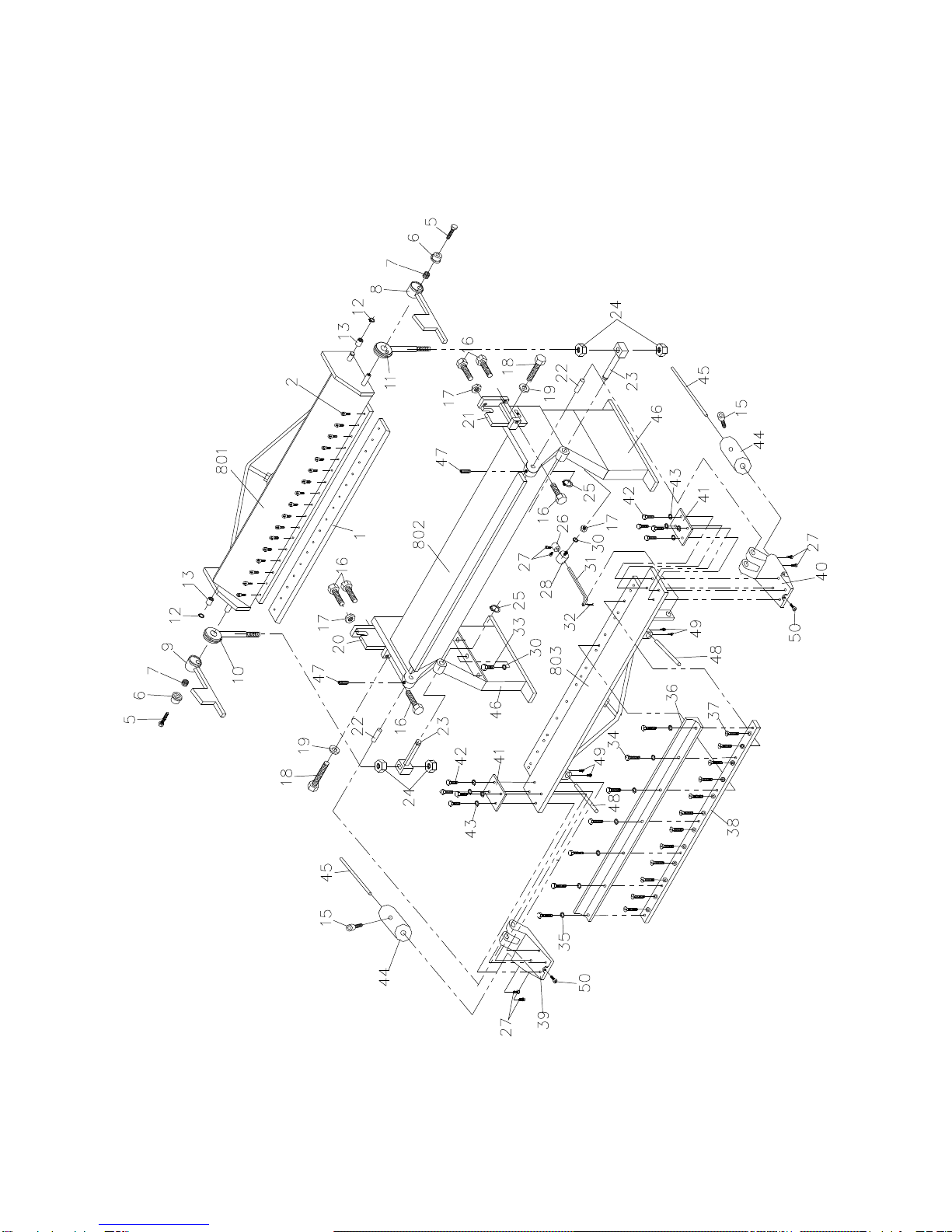
Parts List
Index No Part No Description Size Qty
1...............HB1697F-01 ............Top Blade..............................................................................................1
2...............HB1697F-02 ............Socket Cap Screw..............................................M10×25....................17
5...............HB1697H-05............Hex Head Screw ................................................M16×35......................2
6...............HB1697H-06............Cover....................................................................................................2
7...............HB1697H-07............Spring....................................................................................................2
8...............HB1697F-06 ............Clamp Handle R.H.................................................................................1
9...............HB1697F-09 ............Clamp Handle L.H.................................................................................1
10.............HB1697F-9 ..............Toggle Assembly L.H. ...........................................................................1
11.............HB1697F-08 ............Toggle Assembly R.H. ..........................................................................1
12.............HB1697F-10 ............C-Clip.................................................................20mm.........................2
13.............HB1697F-11 ............Brass Bushing....................................................26×20.2×20................2
15.............TS-1506041.............Socket Head Cap Screw.....................................M12×35....................30
16.............HB1697F-13 ............Hex Head Screw ................................................M12×80......................6
17.............TS-1540081.............Hex Nut..............................................................M12 ...........................7
18.............TS-2213501.............Hex Head Screw ................................................M16×50......................2
19.............TS-155010...............Plain Washer......................................................16mm.........................2
20.............HB1697H-20............Step Bracket Comp.L.H.........................................................................1
21.............HB1697H-21............Step Bracket Comp.R.H.........................................................................1
22.............HB1697F-17 ............Brass Pivot Pin......................................................................................2
23.............HB1697F-18 ............Swivel Pin Assembly..............................................................................2
24.............TS-1540231.............Hex Nut..............................................................M24............................4
25.............HB1697H-25............C-Clip.................................................................32mm.........................2
26.............HB1697F-16 ............Gauge Stop...........................................................................................1
27.............TS-1505041.............Socket Cap Screw..............................................M10×30......................6
28.............HB1697F-15 ............Gauge Ring...........................................................................................1
30.............TS-2361121.............Spring Washer....................................................12mm.........................7
31.............HB1697F-24 ............Gauge Rod............................................................................................1
32.............HB1697H-32............Cotter Pin...........................................................4×35mm.....................1
33.............TS-1492031.............Hex Head Screw ................................................M12×35......................6
34.............TS-1505051.............Socket Cap Screw..............................................M10×35......................7
35.............TS-1550071.............Plain Washer......................................................10mm.........................7
36.............HB1697F-36 ............Angle Bar..............................................................................................1
37.............TS-1516011.............Socket Head Flat Screw.....................................M10×20....................12
38.............HB1697F-38 ............Insert Bar ..............................................................................................1
39.............HB1697F-39 ............Support Apron Assembly L.H.................................................................1
40.............HB1697F-40 ............Support Apron Assembly R.H................................................................1
41.............HB1697F-41 ............Fixing Plate ...........................................................................................2
42.............TS-1492051.............Hex Head Screw ................................................M12×50......................8
43.............TS-2360121.............Plain Washer......................................................12mm.........................8
44.............HB1697F-20 ............Counterweight .......................................................................................2
45.............HB1697F-45 ............Counterweight Rod................................................................................2
46.............HB1697H-46............Stand ....................................................................................................2
47.............TS-1525041.............Set Screw...........................................................M10×20......................2
48.............HB1697H-48............Bending Handle.....................................................................................2
49.............TS-1491031.............Hex Head Screw ................................................M10×25......................4
50.............TS-1506031.............Socket Head Cap Screw.....................................M12×30......................2
800...........BP1696F-800...........Hold-down Assembly.............................................................................1
802...........HB1697H-802..........Base Assembly
......................................................................................1
803...........HB1697F-803 ..........Apron Assembly....................................................................................1

7
Assembly Drawing

8
WALTER MEIER (Manufacturing) Inc.
427 New Sanford Road
LaVergne, Tennessee 37086
Phone: 800-274-6848
www.waltermeier.com
Table of contents
Other Jet Tools manuals
Popular Tools manuals by other brands

Clarke
Clarke CDTJ12 Operation & maintenance instructions

Westfalia
Westfalia 50 50 81 instruction manual

Parkside
Parkside PDSSA 20-Li A1 Translation of the original instructions

Trax
Trax ARX-0123A Operation, maintenance & instruction manual

JEM
JEM ASM 14-4 Repair instructions

Milwaukee
Milwaukee HEAVY DUTY BTT Original instructions