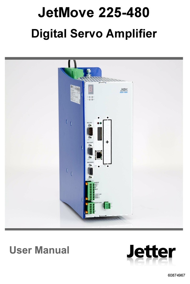
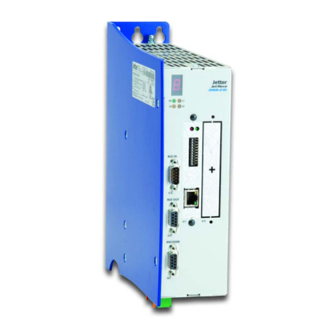
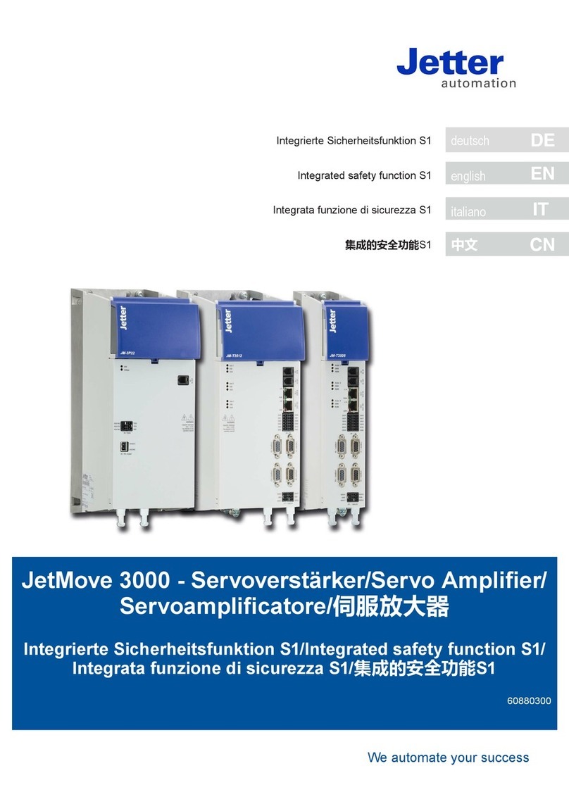
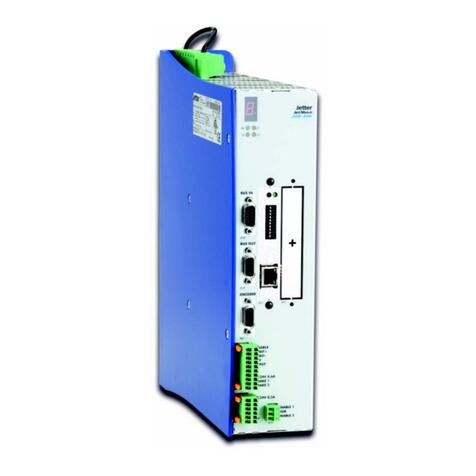
Jetter JetMove D203 User manual

User Manual
JM-D203-230 - Digital Servoamplifier
60870727
We automate your success.

Introduction
2Jetter AG
Article # 608 70 727
Revision 2.16.1
April 2020 / Printed in Germany
Translation of the original German language document.
Jetter AG reserves the right to make alterations to its products in the interest of
technical progress. These alterations need not be documented in every single case.
This manual and the information contained herein have been compiled with due
diligence. However, Jetter AG assume no liability for printing or other errors or
damages arising from such errors.
The brand names and product names used in this document are trademarks or
registered trademarks of the respective title owner.

JetMove D203 Introduction
Jetter AG 3
How to Contact us:
Jetter AG
Graeterstrasse 2
71642 Ludwigsburg
Germany
Phone - Switchboard: ++49 7141/2550-0
Phone - Sales: ++49 7141/2550-433
Phone - Technical Hotline: ++49 7141/2550-444
Fax - Sales: ++49 7141/2550-484
Internet Address: http://www.jetter.de
This Operator's Manual is an Integral
Part of the JetMove D203:
To be entered by the customer:
Type:
Serial #:
Year of construction:
Order #:
Inventory #:
Place of operation:

Introduction
4Jetter AG
Significance of this User Manual
This operator's manual is an integral part of the digital servo amplifier JetMove D203.
• Therefore, keep in a way that it is always at hand until the the digital servo
amplifier JetMove D203 will be disposed of.
• Pass this manual on if the digital servo amplifier JetMove D203 is sold or loaned/
leased out.
In any case you encounter difficulties to clearly understand this user manual, please
contact the manufacturer.
We would appreciate any suggestions and contributions on your part and would ask
you to contact us. This will help us to produce manuals that are more user-friendly
and to address your wishes and requirements.
From the servo amplifier JetMove D203 may result unavoidable residual risks to
persons and property. For this reason, any person who has to deal with the transport,
installation, operation, maintenance, and repair of the digital servo amplifier JetMove
206-230 must have been familiarized with it and must be aware of these dangers.
Therefore, this person must carefully read, understand and observe this manual, and
especially the safety instructions.
Missing or inadequate knowledge of the manual results in the loss of any claim of
liability on part of Jetter AG. Therefore, the operating company is recommended to
have the instruction of the persons concerned confirmed in writing.
JetMove D203 has been designed for controlling two motors. If, in this manual, one
axis is not mentioned explicitely, the description and instructions can be applied both
to axis A and axis B.
System Requirements
This user instruction describes the motion system JetMove D203 of the operating
system version 2.16.0.0.
History
Revision Comment
2.07.1 Chapter 12: Option -JC24X has been added
2.09.1 Modifications: max. device temperature, default IP address
New: Specifications in lbf-inch and AWG, error 28
2.09.2 Modifications in option -S1 (Safe Torque Off)
2.10.1 Further specifications of the motor cable.
See “Recent Revisions” on page 135.
2.10.3 See “Recent Revisions” on page 135.
2.16.1 See “Recent Revisions” on page 135.
JetMove D203 Introduction
Jetter AG 5
Description of Symbols
DANGER
This sign is to indicate a possible impending danger of serious physical damage
or death.
CAUTION
This sign is to indicate a possible impending danger of light physical damage.
This sign is also to warn you of material damage.
This sign indicates hazard of life due to electric shock caused by a high operating
voltage.
This sign is to indicate hazard of serious physical damage or death due to
accidentally touching dangerous parts of the device.
This sign instructs you to wear protective goggles. Failure to comply may lead to
injuries.
This sign is to warn you of material damage due to applying hard blows or shocks
to the motor flange and shaft.
NOTICE
This sign is to indicate a possible impending situation which might bring damage
to the product or to its surroundings.
It also identifies requirements necessary to ensure faultless operation.

Introduction
6Jetter AG
INFO
You will be informed of various possible applications and will receive further
useful suggestions.
It also gives you words of advice on how to efficiently use hardware and software
in order to avoid unnecessary efforts.
· / - Enumerations are marked by full stops, strokes or scores.
Operating instructions are marked by this arrow.
Automatically running processes or results to be achieved are marked by this
arrow.
PC and user interface keys.
This symbol informs you of additional references (data sheets, literature, etc.)
associated with the given subject, product, etc. It also helps you to find your way
around this manual.

JetMove D203 Table of Contents
Jetter AG 7
1 Safety Instructions
1.1 General Safety Instructions
1.2 Ensure your own safety
1.3 Residual Dangers
1.4 Instructions on EMC
2 Installation of the JetMove D203 23
2.1 Scope of Delivery 23
2.2 Mechanical Installation 24
2.3 Electrical Installation 26
2.4 Checking the Installation 27
2.5 Notes on Safety as regards the Installation 27
2.6 Safety Instructions for Commissioning 28
2.7 Notes on decommissioning 28
3 Operating Conditions 29
4 Physical Dimensions 35
5 Technical Data 37
5.1 Electrical Specification 37
5.2 Motor Protection 43
5.2.1 Thermal sensor integrated in the motor 43
5.2.2 I²t calculation 44
5.2.3 Motor overload calculation to UL 45
6 Drive Controller Structure 47
7 Description of Connections 49
7.1 Mains Power Supply 49
7.2 Motor Connection 50
7.2.1 Assignment and Specification 50
7.2.2 General Information 51
7.2.3 Motor cables with SC mating connector 52
7.2.4 Connection assignment of terminal box 55
7.3 Resolver Connection 56
7.3.1 Specifications 56
7.3.2 Resolver cable with mating connector 56
7.4 HIPERFACE Connection 59
7.4.1 Specifications 59
7.4.2 HIPERFACE cable with mating connector 59
7.5 Sin-Cos Encoder Connection 62

Table of Contents
8Jetter AG
7.5.1 Specifications 62
7.6 Incremental Encoder Connection 66
7.6.1 Specifications 66
7.7 Digital Inputs, Logic Power Supply 70
7.7.1 Enable Input without Option -S1
(Safe Torque Off) 73
7.7.2 Enable input with Option -S1
(Safe Torque Off) 74
7.8 JX2 System Bus 74
7.8.1 Specification of the JX2 system bus cable 75
7.9 Analog Input 77
7.9.1 Function 77
7.9.2 Specifications 77
8 Status Monitoring 79
9 Diagnostics 81
9.1 Error Messages 81
9.2 Warnings 86
10 Connection Diagrams 87
11 Option -S1: STO 91
12 Option -JC24X 93
12.1 Electrical Installation 93
12.2 Power Supply 94
12.2.1 Requirements 94
12.2.2 Description of connections 95
12.3 Digital Inputs 96
12.3.1 Technical data 96
12.3.2 Description of the LEDs 97
12.3.3 Description of connections 98
12.3.4 Numbering system of digital inputs
located on expansion modules 99
12.4 Digital Outputs 100
12.4.1 Technical data 100
12.4.2 Description of the LEDs 101
12.4.3 Description of connections 102
12.4.4 Numbering system of digital inputs
located on expansion modules 103
12.5 Serial Interfaces 104
12.6 Ethernet Interface 105

JetMove D203 Table of Contents
Jetter AG 9
12.6.1 Connecting to the RJ45 jack 105
12.6.2 Connection between -JC24X and PC 106
12.6.3 Connection between -JC24X, switch, and PC 106
12.6.4 Connection via several switches 107
12.7 Status LEDs, Mode Selector 109
12.7.1 LEDs 109
12.7.2 The mode selector 111
12.8 Setting the IP Address 112
12.8.1 Default IP address 112
12.8.2 IP address from the configuration memory 112
12.8.3 IP address based on the address switch position 114
12.8.4 Setting the IP address via special function 117
12.9 ON Delay 118
12.10 Interface Cables 119
12.10.1 Overview of interface cables 119
12.10.2 Serial programming cable 120
12.10.3 HMI cable for LCD 16 - 34 and 110 121
12.10.4 HMI cable KAY_0386-xxxx 122
12.10.5 HMI cable KAY_0533-0025 124
12.11 Anybus-CC 126
12.11.1 Installation instructions 126
12.11.2 Prying the break-away shield 126
12.11.3 Inserting the Anybus-CC module 127
13 Ordering Information 129
13.1 List of Documentation 129
13.2 Options 129
13.3 Motor Power Cable with Mating Connector SC 131
13.4 Resolver Cable 132
13.5 HIPERFACE Cable 132
13.6 System Bus Cables 132
List of Appendices
Appendix A: Recent Revisions 135
Appendix B: Glossary 136
Appendix C: List of Illustrations 139
Appendix D: Index 140

Table of Contents
10 Jetter AG

JetMove D203 1.1 General Safety Instructions
Jetter AG 11
1 Safety instructions
1.1 General Safety Instructions
The digital servo amplifier JetMove D203 meets the applicable safety regulations and
standards. Special emphasis was given to the safety of the users.
Further, the user should adhere to the following regulations:
• relevant accident prevention regulations;
• accepted safety rules;
• EC guidelines and other country-specific regulations.
1.1.1 Intended Use
Usage according to the intended conditions of use includes operation in accordance
with these operating instructions.
Operate the digital servo amplifier JetMove D203 only in a closed control cab-
inet and within the range of the specified values, see Chapter 5 "Technical Da-
ta", page 37.
Do not apply a voltage to the digital servo amplifier JetMove D203 that is higher
than the specified operating voltage.
The operating voltage voltage of the JM-D203 is 195 ... 265 VAC (one-phase). Thus,
the digital servo amplifier is subject to the EU Low Voltage Directive.
The JetMove D203 servo amplifier has been designed to drive 3-phase brush-
less synchronous servo motors in the following modes: speed control, torque
control and/or position control. The winding insulation of the motors must be
higher than, or at least equal to, the DC link voltage supplied by the servo am-
plifier.
The digital servo amplifier JetMove D203 is used to drive machinery, such as con-
veyors, production machines, and handling machines.
1.1.2 Usage other than intended
This digital servo amplifier must not be used in technical systems which to a
high degree have to be fail-safe, e.g. ropeways and airplanes.
Do not use the integrated braking circuit in applications, where, in case of
braking circuit failure, safety hazards can occur.
The JetMove D203 is no safety-related part as per Machinery Directive 2006/42/
EC. Therefore, using this servo amplifier for safety-relevant applications as re-
gards safety of persons is neither suitable nor permitted.
An exception to this is the STO function of servo amplifiers with option- S1, see
Chapter 11 "Option -S1: STO", page 91.

1 Safety instructions
12 Jetter AG
If the digital servo amplifier JetMove D203 is to be run under operating conditions,
which differ from the conditions mentioned in Chapter 3 "Operating Conditions", page
29, Jetter AG must be contacted beforehand.
1.1.3 Qualification of Staff
Depending on the life cycle of the product, the persons involved must possess differ-
ent qualifications. These qualifications are required to ensure proper handling of the
JetMove D203 in the corresponding life cycle.
1.1.4 Modifications and Alterations
to the Device
For safety reasons, modifications and alterations to the digital servo amplifier
D203 and its functions are NOT permitted.
Any modifications to the servo amplifier JetMove D203 not expressly authorized by
us will result in the loss of any warranty and liability claims against Jetter AG.
The original parts are specially designed for the servo amplifier JetMove D203.
Parts and equipment from other manufacturers are not tested by Jetter AG,
and are, therefore, not released by Jetter AG.
The installation of such parts may impair the safety and the proper functioning of the
digital servo amplifier JetMove D203.
Any liability on the part of Jetter AG for any damages resulting from the use of non-
original parts and equipment is excluded.
Phase of the product life
cycle
Minimum qualification
Transport/storage: Trained and instructed personnel with knowledge in
handling electrostatically sensitive components.
Mechanical/electrical in-
stallation
Specialized personnel with training in electrical/auto-
motive engineering, such as industrial electronics
engineer.
Commissioning /
Programming
Trained and instructed experts with profound knowl-
edge of, and experience with, electrical / drive engi-
neering, such as electronics engineer for automation
technology.
Operation: Trained, instructed and assigned personnel with
knowledge of operating electronic devices.
Decommissioning: Specialized personnel with training in electrical engi-
neering, such as industrial electronics technician.

JetMove D203 1.1 General Safety Instructions
Jetter AG 13
1.1.5 Repairs and Maintenance
Repairs to the digital servo amplifier JetMove D203 must not be carried out by the
operator. The servo amplifier JetMove D203 does not contain any parts which can
be repaired by the operator.
It must be sent to Jetter AG for repair.
The digital servo amplifier JetMove D203 is maintenance-free. Therefore, absolutely
no inspection or maintenance works are required for the operation of this device.
The controller option "-JC24X" is not maintenance-free. It is equipped with a battery
which must be replaced at regular intervals. The designed service life of the original
battery is more than 10 years. The battery condition can be checked in the following
way:
The actual battery voltage can be read out from the following special register:
The battery can provide data backup up to a voltage of 2.0 V.
If the battery needs to be replaced, please send the JetMove D203 controller to Jetter
AG.
Special register 10183 1: Battery is okay
0: Battery is almost flat
Special register 10184 Actual Battery voltage in 100 mV
Value range: 0 ... 255
INFO
The real-time clock and the RAM for application registers are backed up by the
same battery.

1 Safety instructions
14 Jetter AG
1.1.6 Disposal
In case of obvious damage or erratic behaviour, the servo amplifier must not be used
anymore.
Comply with the local environmental regulations when disposing of the digital servo
amplifier.
The main components of the JetMove D203 (aluminum side walls, steel cover,
PCBs) are connected by screw connections. To disassemble the servo amplifier just
remove the screws.
1.2 Ensure your own Safety
1.2.1 Malfunctions
DANGER
Isolate the JetMove D203 from the mains if maintenance works have to be
carried out. By doing so, you will prevent accidents resulting from electric
voltage and moving parts.
Follow the information given in Chapter 1.3 "Residual Dangers", page 17.
Safety and protective devices, e.g. the guard, cover of the terminal box or
the thermal motor circuit-breaker must never be shunted or by-passed.
Dismantled protective equipment, such as guards and thermal motor cir-
cuit-breakers, must be reattached and checked for proper functioning prior
to commissioning.
Before commissioning, the machine manufacturer must carry out a hazard
analysis of the respective machine and take adequate measures so that
inadvertent motions will not lead to personal injury and to material dam-
age.
See Chapter 11 "Option -S1: STO", page 91.
In the case of malfunctions or other faults, immediately isolate the
JetMove D203 from the mains.
Follow the information given in Chapter 1.3 "Residual Dangers", page 17.
Immediately report any malfunctions or other damages to the responsible
person.
Secure servo amplifier JetMove D203 against misuse or accidental use.

JetMove D203 1.2 Ensure your own Safety
Jetter AG 15
1.2.2 Information Signs and Labels
1.2.3 Earthing Procedure
Follow the instructions given on markings, information signs, and labels.
Keep markings, signs and labels readable.
Replace damaged or unreadable information signs and labels.
Screw the enclosure of the JetMove D203 down to a highly conductive,
plane and earthed panel.
Use the JetMove D203 only in earthed industrial networks with one mains
phase and neutral conductor (TN network, TT network with earthed neutral
point, max. 5,000 A symmetrical rated current at 400/480 V + 10 %).
The digital servo amplifier must not be connected to unearthed or to asym-
metrically earthed networks.
The leakage current of the JetMove 206-230 is higher than 3.5 mA.
Special precautions are necessary to avoid electric shock.
• Connect the protective conductor having a minimum cross-sectional
area of 10 mm2to the PE bolt on the upper side of the housing (1)
or
• Connect the PE conductor having a minimum cross-sectional area of 10
mm2to the PE bolt on the upper side of the housing (1) and the PE
terminal X1 (2) (refer to Fig. 1).
The cross-sectional area of the two PE conductors must be equal to, or
greater than the cross-sectional area of the supply cables (at least
1.5 mm2/AWG 16).
• Provide a permanent connection with the power supply of the JetMove
D203.
• Wire the PE bus according to the connection diagram (refer to Chapter
10 "Connection Diagrams", page 87).
NOTICE
Follow the installation instruction below for the tightening torque of the PE bolt (1)
so that it does not become loose or even break off:
Do not overtighten the nut of the PE bolt (1). The maximum tightening
torque is 3 Nm!

1 Safety instructions
16 Jetter AG
Abb. 1: Double Earthing
1
1
´
2
X
View X
NOTICE
Do not install an earth-leakage current breaker in the supply line.
If this advice is disregarded and an RCD is installed, it will switch off the servo
amplifier although there is no error.
When an earth-leakage current breaker needs to be installed, an isolating trans-
former must be used.

JetMove D203 1.3 Residual Dangers
Jetter AG 17
1.3 Residual Dangers
1.3.1 Hazards during Operation
DANGER
Hazard caused by high operating voltage!
Extremely hazardous voltages of up to DC 500 V may occur!
Such voltages may result in muscle cramps, burns, unconsciousness, respiratory
standstill, or death.
During operation, keep all covers and electric cabinet doors closed.
Do not remove the cover.
Do not disconnect electrical connections of the JetMove D203 while they are
energized.
DANGER
Do not touch the terminals X1, X74 and X84 while the servo amplifier is
running.
The terminal designations mean:
X1: AC 230 V voltage supply
X74, X84: DC motor voltage up to 500 V
CAUTION
Caution! Hot surfaces!
During operation, the surfaces, respectively the heat sinks of the JetMove D203
can heat up. The left sidewall can reach temperatures of up to 80 ¬×C.
Do not touch the left sidewall during operation and after switching off
while the device is still cooling down.
Make sure that no temperature-sensitive parts are in contact with or
attached to the servo amplifier JetMove D203.

1 Safety instructions
18 Jetter AG
DANGER
Hazard in explosive gas atmosphere!
Do not use the JetMove D203 in a potentially explosive atmosphere.
CAUTION
Danger of injuries caused by mechanic force!
The JetMove D203 has been designed for driving a motor. This motor moves
mechanic parts or sharp edges. Therefore, failure or malfunctioning of the Jet-
Move D203 can be dangerous for persons or damage the machinery. This should
be prevented by installing additional safety devices.
• One safety precaution is to install a second set of limit switches to interrupt the
power supply of the motor.
• Another safety precaution would be installing a guard.
Make sure that hazards to persons are precluded even when the drive is
moving unintentionally.
DANGER
Do not remove any guards.
Do not wear gloves. They could get caught in the rotating drive shaft.
Never touch a rotating drive shaft.

JetMove D203 1.3 Residual Dangers
Jetter AG 19
1.3.2 Hazards after POWER is turned OFF
DANGER
Danger resulting from electric shock!
Capacitors of the servo amplifier can store dangerous voltages up to 5 minutes
after switching off the operating voltage.
Wait always at least 5 minutes after switching off, before touching live
parts or disconnecting terminal leads.
Do not
– touch the screws of terminals X1, X74 and X84 when the connectors are
inserted;
– unplug connectors and do not touch the contacts.

1 Safety instructions
20 Jetter AG
1.4 Instructions on EMC
The digital servo amplifier JetMove D203 is intended for use in industrial environ-
ment. It may cause radio interferences when used in residential areas. It is operated
at the operator's own risk.
The noise immunity of a system is determined by the weakest component of the sys-
tem. For this reason, correct wiring and shielding of cables is of paramount impor-
tance.
NOTICE
Measures for increasing immunity to interference:
Earth the device adequately according to Chapter 1.2.3 "Earthing Proce-
dure", page 15.
Be sure to connect all protective earth terminals of the JetMove D203.
Double earthing is necessary!
– Connect the PE bolt located on the enclosure.
– Connect the protective earth (PE) conductor to terminal X1.
See Abb. 1 on Seite 16
Connect the motor cable. An optional line filter must be installed close to
the servo amplifier. Shield cables on both ends.
If a motor power cable is used which includes cores for brake control, the
brake control cores must be separately shielded. Ground the shielding
braid on both ends.
Keep the distance between optional mains filters and the JetMove D203 as
short as possible.
Follow the instructions given in Application Note 016 "EMC-Compatible
Installation of the Electric Cabinet" published by Jetter AG.
The following instructions are excerpts from Application Note 016:
Screw the enclosure of the JetMove D203 down to a highly conductive,
plane and earthed panel.
On principle, physical separation should be maintained between signal
and power lines. We recommend spacing greater than 20 cm. Cables and
lines should cross each other at an angle of 90¬×.
Shielded cables must be used for the following lines:
Analog lines, data lines, motor cables coming from inverter drives (servo
output stage, frequency converter), lines between components and inter-
ference suppressor filter, if the suppressor filter has not been placed at the
component directly.
This manual suits for next models
1
Table of contents
Other Jetter Amplifier manuals

Jetter
Jetter JetWeb JetMove 203-230 User manual

Jetter
Jetter JM-108 User manual

Jetter
Jetter JetMove 225-480 User manual

Jetter
Jetter JM-204-480 User manual

Jetter
Jetter JM-203B-230 User manual

Jetter
Jetter JetMove 208-480 User manual

Jetter
Jetter JM-206-230 User manual

Jetter
Jetter JetMove 204-480 User manual

Jetter
Jetter JM-1008 User manual

Jetter
Jetter JetMove 3000 User manual