manuals.online logo
Brands
  1. Home
  2. •
  3. Brands
  4. •
  5. Johnson Controls
  6. •
  7. Touch Terminal
  8. •
  9. Johnson Controls FlexSys MIT3-CN User manual

Johnson Controls FlexSys MIT3-CN User manual

FlexSys Underoor Air Terminal (Variable Volume)
MIT3 - CN
Model:
©2016 Johnson Controls | The performance specications are nominal and conform to acceptable industry standards. For applications at conditions beyond these specications, consult the local
Johnson Controls ofce. Johnson Controls, Inc. shall not be liable for damages resulting from misapplication or misuse of its products.
© 2016 AirFixture, LLC
1
Installation / Operation Manual
V160803
TOOLS REQUIRED:
1. Power Screwdriver
• Phillips #3 Bit - oor panel screws
• Phillips #2 Bit - grille trim ring screws
2. Panel Lifter (Suction Cups) - remove oor panel
3. Jigsaw - cut opening in oor panel (if panels are not pre-cut)
4. Carpet Knife - cut opening in carpet tile / oor covering
MATERIALS REQUIRED:
1. MIT3-CN Underoor Air Distribution Terminal
2. Plug & Play Cable (PAP-1)
3. #8 – 32 x 1-1/2" (38.1mm) Self-Drilling/Tapping Sheet Metal
Screws (1-1/2" screws work in most applications; using other
screws could void warranty)
PREPARATION:
1. Verify that MIT3-CN is the correct model, unit count and
location(s) per scheduled placement.
2. Remove oor covering (carpet tile) / oor panel at desired
location(s) (if installed).
3. Verify that all adjacent oor panels are properly installed.
INSTALLATION:
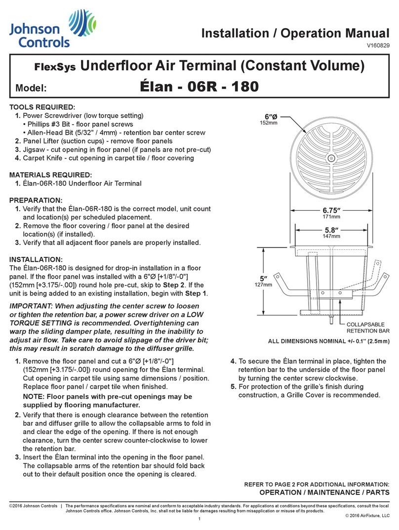
The MIT3-CN is designed to be installed into a oor panel that
has been removed from the oor. The completed assembly is
then installed back into the oor and connected to a designated
VAV operational zone with Plug & Play Cables.
If the oor panel / carpet tile was installed with a 10-1/2" x 5-1/2"
[+1/8"/-0"] (267mm x 140mm [+3.175/-.00]) rectangle hole pre-cut,
skip to Step 2. If the unit is being added to an existing installation,
begin with Step 1.
IMPORTANT: It is HIGHLY RECOMMENDED by the
manufacturer that each zone be checked for faulty
or improper wiring DURING INSTALLATION. Each
zone should be tested thorougly for full connectivity
before proceeding with installation of the next
zone. The manufacturer cannot be responsible for
any improper installation as a result of failure to
follow this procedure as outlined in the FlexSys
Connectivity Testing Procedures.
!
CAUTION
REFER TO PAGE 2 FOR ADDITIONAL INFORMATION:
INSTALLATION / OPERATION / MAINTENANCE / PARTS ALL DIMENSIONS NOMINAL +/- 0.1" (2.5mm)
5.4”
137mm
10.4”
264mm
15”
381mm
4.8”
121mm
3”
79mm
5.3”
133mm
7”
143mm
11 .4”
289mm
6.4”
162mm
5”
127mm
10”
254mm
FlexSys Underoor Air Terminal (Variable Volume)
MIT3 - CN
Model:
©2016 Johnson Controls | The performance specications are nominal and conform to acceptable industry standards. For applications at conditions beyond these specications, consult the local
Johnson Controls ofce. Johnson Controls, Inc. shall not be liable for damages resulting from misapplication or misuse of its products.
© 2016 AirFixture, LLC
2
Installation / Operation Manual
V160803
INSTALLATION (CONTINUED):
1. Remove oor panel and cut 10-1/2" x 5-1/2" [+1/8"/-0"]
(267mm x 140mm [+3.175/-.00]) rectangle opening for MIT
terminal. Cut opening in carpet tile using same dimensions /
position.
NOTE: Floor panels with pre-cut openings may be
supplied by ooring manufacturer.
2. Remove trim ring and grille insert from MIT terminal. Remove
package of trim ring screws from interior of terminal (screws
may be provided in a separate box on shipping pallet).
3. Set MIT terminal on work surface. Lay oor panel on top of
terminal, so that rectangle collar ts through pre-cut opening.
Place carpet tile in position on top of oor panel.
4. Insert trim ring into MIT terminal.
IMPORTANT: Align trim ring screw holes with
corresponding holes on sides of rectangle collar.
5. Secure trim ring to MIT terminal, using included screws to
hold assembly together.
6. Replace oor panel (with installed MIT terminal / trim ring).
Orient panel so that air valve opening is directed away from
exterior walls.
7. Connect MIT terminal to designated VAV operational zone,
using Plug & Play Cables connected to molex inputs located
on air valve actuator.
8. Conrm air valve operation – spin damper by hand to verify
it is free to move. Incorrect routing of cables and other
underoor obstructions can interfere with operation.
9. Replace oor panel screws to secure oor panel / MIT
assembly in place.
10. Place grille insert into trim ring in desired orientation.
OPTIONAL: Tighten security screws (if provided).
11. For protection of diffuser grille nish during construction,
a Grille Cover is recommended.
Use only #8 Phillips Head Sheet Metal Screws.
Using other screws could void warranty.
!
CAUTION
OPERATION:
Once installed, the MIT3-CN requires no
direct input or adjustment for proper operation.
MAINTENANCE:
At least once a year, it is recommended to
clean the interior of the MIT3-CN terminal.
1. Remove grille insert, and carefully vacuum
any loose debris from interior of terminal.
2. After cleaning, replace grille insert.
PARTS:
• Grille Cover: P/N 620.0120.05

Other Johnson Controls Touch Terminal manuals

Johnson Controls FlexSys Elan-06R-180 User manual

Johnson Controls

Johnson Controls FlexSys Elan-06R-180 User manual

Johnson Controls METASYS Zone Terminal Assembly instructions

Johnson Controls

Johnson Controls METASYS Zone Terminal Assembly instructions

Johnson Controls TVS User manual

Johnson Controls

Johnson Controls TVS User manual

Johnson Controls METASYS User manual

Johnson Controls

Johnson Controls METASYS User manual

Johnson Controls METASYS Series Assembly instructions

Johnson Controls

Johnson Controls METASYS Series Assembly instructions

Popular Touch Terminal manuals by other brands

Control Data Corporation CDC721 - XO Hardware reference manual

Control Data Corporation

Control Data Corporation CDC721 - XO Hardware reference manual

FlyTech POS 554 user manual

FlyTech

FlyTech POS 554 user manual

First Data EFTPOS user guide

First Data

First Data EFTPOS user guide

HP ap5000 Quick setup

HP

HP ap5000 Quick setup

takepayments M5000 installation guide

takepayments

takepayments M5000 installation guide

Siemens 3VF8 operating instructions

Siemens

Siemens 3VF8 operating instructions

Festo CPX-AB Series Electronic manual

Festo

Festo CPX-AB Series Electronic manual

Gira Info-Terminal installation instructions

Gira

Gira Info-Terminal installation instructions

Amano OPUS-4000 Series manual

Amano

Amano OPUS-4000 Series manual

Protech Systems PA-6222 Quick reference guide

Protech Systems

Protech Systems PA-6222 Quick reference guide

SCM Microsystems SCL01X Reference manual

SCM Microsystems

SCM Microsystems SCL01X Reference manual

TeleVideo 955 Service manual and maintenance instructions

TeleVideo

TeleVideo 955 Service manual and maintenance instructions

VeriFone Vx680 3G Series installation guide

VeriFone

VeriFone Vx680 3G Series installation guide

Mitsubishi Electric GT2103-PMBD manual

Mitsubishi Electric

Mitsubishi Electric GT2103-PMBD manual

AT&T callmaster user guide

AT&T

AT&T callmaster user guide

Bosch Rexroth IndraControl VEH 30.1 Project planning manual

Bosch

Bosch Rexroth IndraControl VEH 30.1 Project planning manual

Topcon WT-100 instruction manual

Topcon

Topcon WT-100 instruction manual

Motorola VT1000 user guide

Motorola

Motorola VT1000 user guide

manuals.online logo
manuals.online logoBrands
  • About & Mission
  • Contact us
  • Privacy Policy
  • Terms and Conditions

Copyright 2025 Manuals.Online. All Rights Reserved.