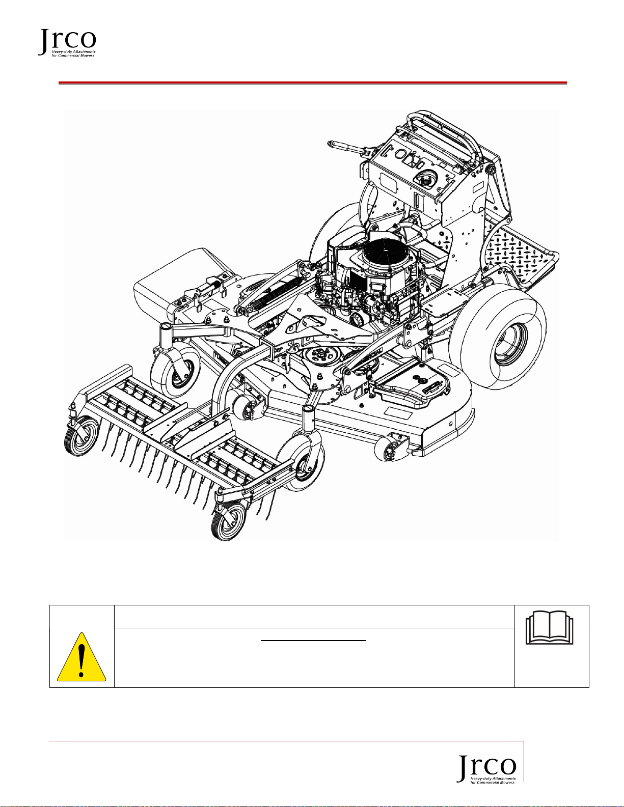
Operator’s Manual Tine Rake Dethatcher
20195 South Diamond Lake Road, STE 100
Rogers, MN 55374
800.966.8442
www.jrcoinc.com
2
Table of Contents
1 Introduction ................................................................................................................................................................ 3
1.1 ... Application ............................................................................................................................................................................3
1.2 ... Navigating This Manual ..................................................................................................................................................3
1.3 ... Operation References/Terminology ..........................................................................................................................3
1.4 ... Owner Assistance ................................................................................................................................................................3
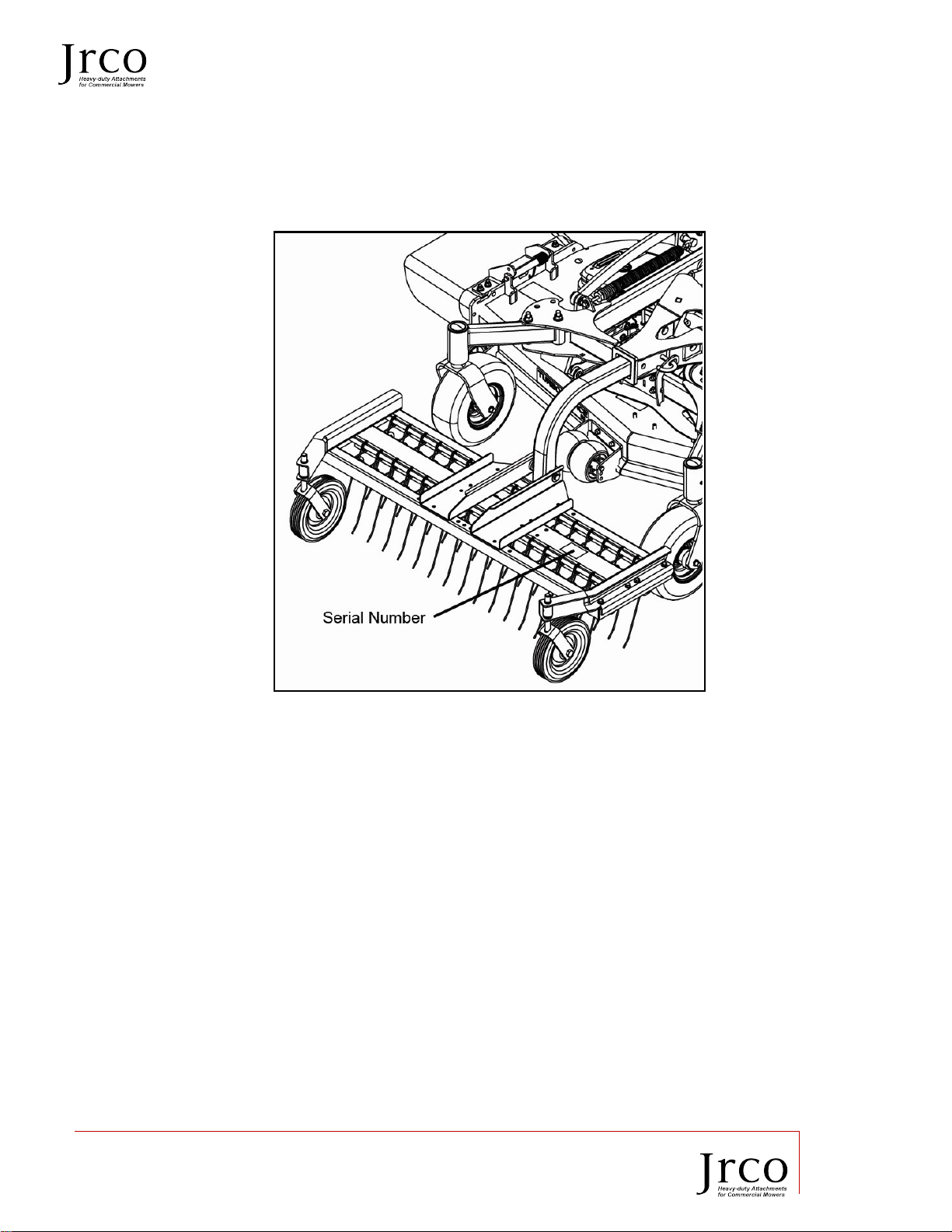
1.5 ... Model Identification ..........................................................................................................................................................4
1.6 ... Further Assistance .............................................................................................................................................................4
2 Assembly and Set-up ............................................................................................................................................... 5
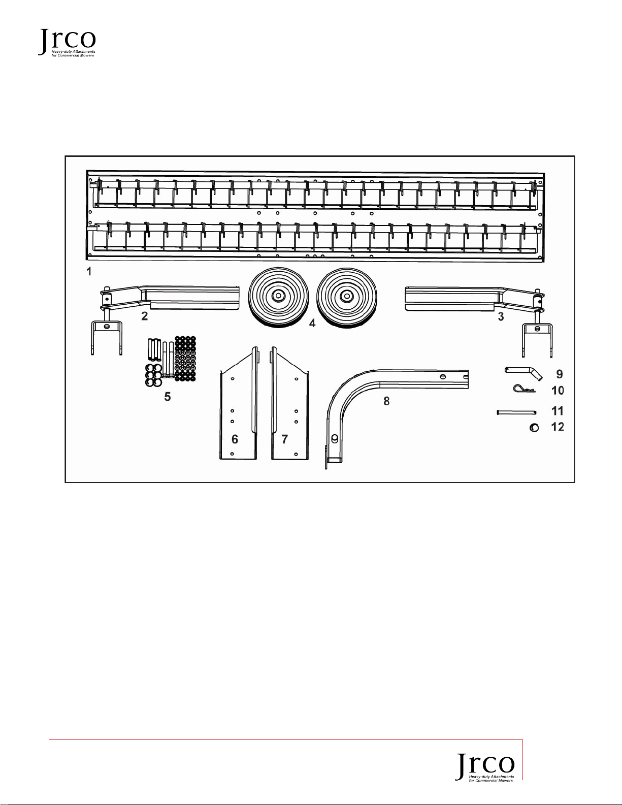
2.1 ... Packing List ...........................................................................................................................................................................5
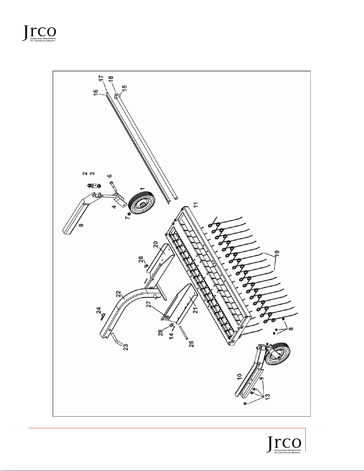
2.2 ... Parts Breakdown ................................................................................................................................................................6
2.3 ... Tools Required .....................................................................................................................................................................7
2.4 ... Power Unit Requirements ...............................................................................................................................................7
2.5 ... Unpacking Your Attachment .........................................................................................................................................8
2.6 ... Torque Requirements .......................................................................................................................................................8
3 Assembly ...................................................................................................................................................................... 8
3.1 ... General Assembly ................................................................................................................................................................8
3.2 ... Wheels to Yokes Assembly ..............................................................................................................................................8
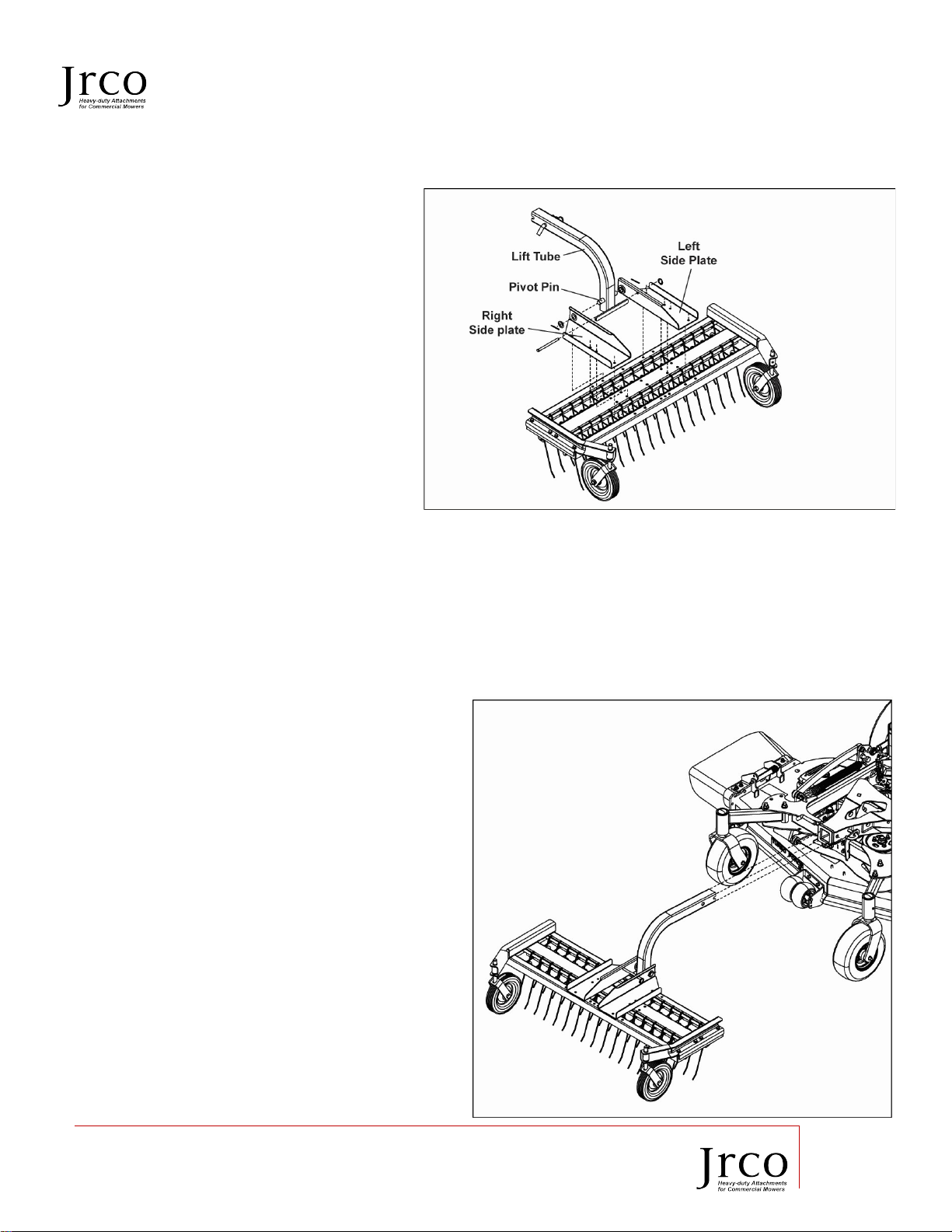
3.3 ... Side plate and Lift Tube attachment .........................................................................................................................9
4 Attach Dethatcher to Reciever Hich .................................................................................................................. 9
5 Adjustments ............................................................................................................................................................. 10
6 Operation Instructions ........................................................................................................................................ 11
6.1 ... Before Operation.............................................................................................................................................................. 11
6.2 ... Operator Safety ................................................................................................................................................................ 11
6.3 ... Operation ............................................................................................................................................................................ 12
7 Storage Instructions ............................................................................................................................................. 13
7.1 ... Storing Your Tine Rake Dethatcher ........................................................................................................................ 13
8 Removing Rake ....................................................................................................................................................... 13
8.1 ... Removing Your Tine Rake Dethatcher .................................................................................................................. 13
9 Field Use Set-up and Instructions ................................................................................................................... 13
10 Specifications ........................................................................................................................................................... 13
11 Maintenance Instructions .................................................................................................................................. 14
11.1 . General ................................................................................................................................................................................. 14
11.2 . Replacing Tines ................................................................................................................................................................ 14