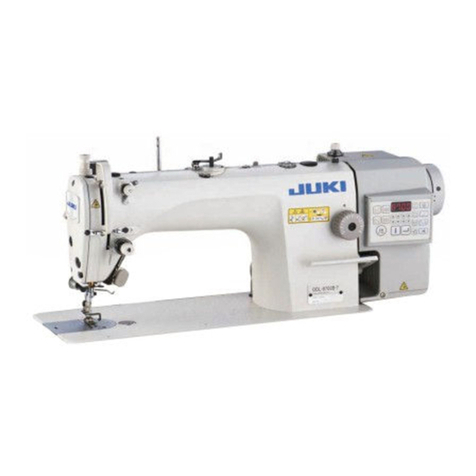
JUKI LS-2342 User manual

LS-2342, 2342-7
INSTRUCTION MANUAL

i
CONTENTS
1. SPECIFICATIONS............................................................................................................ 1
2. INSTALLATION................................................................................................................ 3
2-1. Attaching the drain container ............................................................................................................ 3
2-2. Installation of the sewing machine.................................................................................................... 3
2-3. Pneumatic components...................................................................................................................... 5
2-4. Installing the thread stand ................................................................................................................. 6
3. PREPARATION OF THE SEWING MACHINE ................................................................ 7
3-1. Lubrication...........................................................................................................................................7
3-2. Attaching the needle ........................................................................................................................... 8
3-3. Attaching and removing the bobbin.................................................................................................. 8
3-4. Threading the hook............................................................................................................................. 9
3-5. Winding a bobbin ................................................................................................................................ 9
3-6. Threading the machine head ........................................................................................................... 10
3-7. How to set the model of the machine head .................................................................................... 11
3-8. Adjusting the machine head ............................................................................................................ 12
4. ADJUSTING THE SEWING MACHINE ......................................................................... 14
4-1. Adjusting the stitch length ............................................................................................................... 14
4-2. Thread tension ..................................................................................................................................15
4-3. Thread take-up spring ...................................................................................................................... 16
4-4. Adjusting the pressure of the presser foot.....................................................................................16
4-5. Needle-to-hook relation .................................................................................................................... 17
4-6. Adjusting the hook needle guard .................................................................................................... 18
4-7. Adjusting the bobbin case opener .................................................................................................. 18
4-8. Position of the counter knife and adjustment of the knife pressure (LS-2342S-7, 2342H-7) ..... 19
4-9. Adjusting the amount of the alternating vertical movement of the walking foot and the presser
foot .....................................................................................................................................................19
5. OPERATION OF THE SEWING MACHINE................................................................... 20
5-1. Hand lifter ..........................................................................................................................................20
5-2. Resetting the safety clutch .............................................................................................................. 20
5-3. Fixing the feed adjusting dial........................................................................................................... 20
5-4. Normal-/reverse-feed stitch needle entry points alignment at the time of automatic reverse
feed stitching (LS-2342S-7, 2342H-7) .............................................................................................. 21
5-5. Operation switches ........................................................................................................................... 22
5-6. Knee switch (LS-2342S-7, 2342H-7)................................................................................................. 24
6. SEWING SPEED TABLE ............................................................................................... 27
7. TROUBLES IN SEWING AND CORRECTIVE MEASURES......................................... 28

– 1 –
1. SPECIFICATIONS
No. Item Application
1 Model LS-2342S LS-2342S-7
2 Model name Cylinder-bed, 1-needle, unison-feed,
lockstitch machine
(Standard type)
Cylinder-bed, 1-needle, unison-feed,
lockstitch machine with automatic thread
trimmer (Standard type)
3 Application Medium- to heavy-weight materials, car seat, furniture
4 Sewing speed Max. 2,500 sti/min (See "6. SEWING SPEED TABLE" p.27.) *1
5 Needle SCHMETZ 134-35
(Nm 100 to Nm 180, Standard : Nm 140)
6 Applicable thread size for sewing #40 to #5
(US : #33 to #138, Europe : 90/3 to 20/3)
#30 to #5
(US : #46 to #138, Europe : 60/3 to 20/3)
7 Applicable thread size to be cut #30 to #5
(US : #46 to #138, Europe : 60/3 to 20/3)
8 Stitch length Max. 9 mm (forward/reverse feed)
9 Stitch length dial 1-pitch dial 2-pitch dial
10 Presser foot lift Hand lifter : 10 mm, Automatic presser foot lifter : 20 mm
11 Stitch length adjusting mechanism By dial
12 Reverse stitch adjusting method By lever Air cylinder type
(with touch-back switch)
13 Thread take-up Link type
14 Needle bar stroke 40 mm
15 Amount of the alternate vertical
movement
1 mm to 9 mm (Alternate vertical dial adjustment type)
16 Hook Full-rotary vertical-axis 1.6-fold hook (Latch type)
17 Feed mechanism Elliptical feed
18 Top and bottom feed actuation
mechanism
Timing belt
19 Thread trimming method Cam-driven scissors type
20 Lubrication Concentrated tank type oil wick lubrication (partially by manual)
21 Lubricating oil JUKI New Defrix Oil No. 2 (equivalent to ISO standard VG32)
22 Tube diameter 72 mm
23 Space under the arm 347 mm × 127 mm
24 Hand wheel size Outer diameter : ø123 mm
25 Motor/Control box SC-922B
26 Machine head weight 61 kg 63 kg
27 Rated power consumption 310VA
28 Noise - Equivalent continuous emission sound
pressure level (LpA) at the workstation:
A-weighted value of 83.0 dB; (Includes
KpA = 2.5 dB); according to ISO 10821-
C.6.3 - ISO 11204 GR2 at 2,500 sti/min.
- Sound power level (LWA);
A-weighted value of 89.5 dB; (Includes
KWA = 2.5 dB); according to ISO 10821-
C.6.3 - ISO 3745 GR2 at 2,500 sti/min.
- Equivalent continuous emission sound
pressure level (LpA) at the workstation:
A-weighted value of 77.5 dB; (Includes
KpA = 2.5 dB); according to ISO 10821-
C.6.3 - ISO 11204 GR2 at 2,500 sti/min.
*1 The speed setting according to the amount of the alternating vertical movement of the walking foot and presser
foot is automatically carried out.
– 2 –
No. Item Application
1 Model LS-2342H LS-2342H-7
2 Model name Cylinder-bed, 1-needle, unison-feed,
lockstitch machine
(Thick-thread type)
Cylinder-bed, 1-needle, unison-feed,
lockstitch machine with automatic thread
trimmer (Thick-thread type)
3 Application Medium- to heavy-weight materials, car seat, furniture
4 Sewing speed Max. 2,000 sti/min (See "6. SEWING SPEED TABLE" p.27.) *1
5 Needle SCHMETZ 134-35
(Nm 100 to Nm 180, Standard : Nm 180)
6 Applicable thread size for sewing #20 to #0 (US : #69 to #266, Europe : 40/3 to 10/3)
7 Applicable thread size to be cut #20 to #0
(US : #69 to #266, Europe : 40/3 to 10/3)
8 Stitch length Max. 9 mm (forward/reverse feed)
9 Stitch length dial 1-pitch dial 2-pitch dial
10 Presser foot lift Hand lifter : 10 mm, Automatic presser foot lifter : 20 mm
11 Stitch length adjusting mechanism By dial
12 Reverse stitch adjusting method By lever Air cylinder type
(with touch-back switch)
13 Thread take-up Link type
14 Needle bar stroke 40 mm
15 Amount of the alternate vertical
movement
1 mm to 9 mm (Alternate vertical dial adjustment type)
16 Hook Full-rotary vertical-axis 1.6-fold hook (Latch type)
17 Feed mechanism Box feed
18 Top and bottom feed actuation
mechanism
Timing belt
19 Thread trimming method Cam-driven scissors type
20 Lubrication Concentrated tank type oil wick lubrication (partially by manual)
21 Lubricating oil JUKI New Defrix Oil No. 2 (equivalent to ISO standard VG32)
22 Tube diameter 72 mm
23 Space under the arm 347 mm × 127 mm
24 Hand wheel size Outer diameter : ø123 mm
25 Motor/Control box SC-922B
26 Machine head weight 61 kg 63 kg
27 Rated power consumption 310VA
28 Noise - Equivalent continuous emission sound
pressure level (LpA) at the workstation:
A-weighted value of 83.0 dB; (Includes
KpA = 2.5 dB); according to ISO 10821-
C.6.3 - ISO 11204 GR2 at 2,000 sti/min.
- Sound power level (LWA);
A-weighted value of 91.0 dB; (Includes
KWA = 2.5 dB); according to ISO 10821-
C.6.3 - ISO 3745 GR2 at 2,000 sti/min.
- Equivalent continuous emission sound
pressure level (LpA) at the workstation:
A-weighted value of 78.0 dB; (Includes
KpA = 2.5 dB); according to ISO 10821-
C.6.3 - ISO 11204 GR2 at 2,000 sti/min.
*1 The speed setting according to the amount of the alternating vertical movement of the walking foot and presser
foot is automatically carried out.

– 3 –
1) To prevent possible accidents caused by the full of
the sewing machine, perform the work by two per-
sons or more when the machine is moved.
Loosen bed cover mounting screws ❶(three lo-
cations) to remove them. Remove bed cover ❷.
Then, carry the sewing machine by holding pulley
cover ❸.
Do not hold the handwheel and the reverse
feed lever.
2) Do not put protruding articles such as the screw-
driver and the like at the location where the sewing
machine is placed.
❶
❷
❹
❸
1) Attach oil extractor ❶onto the top surface of the
machine table, and x it with setscrew ❷and wash-
er ❸.
2) After xing oil extractor ❶, screw drain container ❹
in the oil extractor.
2-1. Attaching the drain container
2-2. Installation of the sewing machine
2. INSTALLATION
❶
❸
❷

– 4 –
3) Fix the sewing machine in the four places of the ma-
chine table with countersunk screws ❹, washers ❺
and nuts ❻supplied with the sewing machine.
4) Securely attach head support rod ❼to the table
until it goes no further.
5) Mount spacers ❽supplied with the machine head
on the frame.
6) Install bracket on CP panel ❾with screws
supplied with the panel.
7) Install bracket on spacer ❽with screws sup-
plied with the machine head and washers sup-
plied with the panel.
Do not use the screws supplied the panel
instead of screws supplied with the ma-
chine head.
* Accessory screw supplied with the machine head :
Thread diameter M5; Length 8 mm
❼
❽
❾
❹
❺
❻

– 5 –
(2) Installing the regulator
1) Install regulator (asm.) ❶on mounting plate ❺with
screw ❷, spring washer ❸and nut ❹which are
supplied with the unit.
2) Install couplings ❻and ❼on regulator ❶.
3) Attach mounting plate ❺on the undersurface of the
table with accessory screws ❽supplied with the
plate.
4) Connect ø6 air tube coming from the sewing ma-
chine to coupling ❻.
❷
❶
❺
❻
❼
❹
❸
❽
(1) Routing the air tube and cables
Pass the air tube and cables ❶through hole ❷in the
table down to the undersurface.
If humidity is high, water may leak from ø8 air tube ❸
for exhaust coming from the sewing machine.
(3) Adjusting the air pressure
1) The operating air pressure is 0.5 to 0.55 MPa.
Adjust the air pressure using air pressure regulating
knob ❶ of the lter regulator.
2) In the case uid accumulation is observed in Asec-
tion of the lter regulator, turn drain cock ❷to drain
the uid.
Decrease Increase
❶
❷
A
2-3. Pneumatic components
WARNING :
To protect against possible personal injury due to abrupt start of the machine, be sure to start the follow-
ing work after turning the power off and ascertaining that the motor is at rest.
❸
❶
❷

– 6 –
2-4. Installing the thread stand
Assemble the thread stand, set it up on the machine
table using the installation hole in the table and tighten
nut ❶gently.
❶

– 7 –
3-1. Lubrication
If oil is excessively applied to A, B, Cand D, oil may drop from the throat plate base cover. Periodi-
cally wipe out oil on the throat plate base cover.
1) Be sure to lubricate the section indicated with arrows Ato Dwith an adequate amount of oil once a day be-
fore starting the operation.
2) Eis oil tank. Be sure to add oil to the oil tank approximately once a week.
3) Apply appropriate amount of oil to the arrowed sections when you operate the sewing machine for the rst time
after the purchase or after the machine has been left unused for an extended period of time.
3. PREPARATION OF THE SEWING MACHINE
WARNING :
1. Do not connect the power plug until the lubrication has been completed so as to prevent accidents due
to abrupt start of the sewing machine.
2.Topreventtheoccurrenceofaninammationorrash,immediatelywashtherelatedportionsifoilad-
heres to your eyes or other parts of your body.
3. If oil is mistakenly swallowed, diarrhea or vomiting may occur. Put oil in a place where children cannot
reach.
C
B
A
D
E

– 8 –
3-2. Attaching the needle
3-3. Attaching and removing the bobbin
Use 134-35 needles.
1) Turn the handwheel to bring the needle bar to the
highest position of its stroke.
2) Loosen needle clamp screw ❷. Hold the needle so
that the long groove on needle ❶faces directly to
the right.
3) Push needle ❶deep into the needle clamp hole
until it will go no further.
4) Tighten needle clamp screw ❷ rmly.
When replacing the needle, check the clearance provided between the needle and the blade point
of hook. (Refer to "4-5. Needle-to-hook relation" p.17 and "4-6. Adjusting the hook needle guard"
p.18.)
If there is no clearance, the needle and the hook will be damaged.
1) Lift latch ❶of hook, and take out the bobbin.
2) Put the bobbin into the shaft in the hook correctly
and release the latch ❶.
Do not make the machine run idle with the
bobbin (bobbin thread). The bobbin thread
is caught in the hook. As a result, the hook
may be damaged.
WARNING :
To protect against possible personal injury due to abrupt start of the machine, be sure to start the follow-
ing work after turning the power off and ascertaining that the motor is at rest.
WARNING :
To protect against possible personal injury due to abrupt start of the machine, be sure to start the follow-
ing work after turning the power off and ascertaining that the motor is at rest.
❶
❶
❷
Long groove

– 9 –
1) Pass the bobbin thread through threading groove ❶
in the inner hook and through space ❷provided be-
tween the bobbin case opener and the inner hook.
Then, slowly draw the thread. Now, the bobbin
thread passes under the tension spring.
Then, for the sewing machine with a thread trimmer,
pass the thread through thread hole ❸in the lever
section and pull it out upward.
2) Make sure that the bobbin revolves in the direction
of the arrow when you draw the thread.
1) Pass the thread through sections ❶to ❹in the
numerical order.
2) Put the thread until the root of bobbin thread clamp
❺is reached. Then, trim the thread. (The thread
end is retained under the looper thread clamp.)
3) Load a bobbin on bobbin winder shaft ❻.
4) Press bobbin winder lever ❼in the direction of the
arrow.
5) When you start the sewing machine, the bobbin
rotates to automatically wind the thread on itself.
6) When the bobbin is lled up, the bobbin winder lever
❼automatically releases the bobbin and the bobbin
winder stops running.
1. The bobbin thread winding amount is
adjusted by loosening setscrew ❽. The
bobbin thread winding amount is in-
creased by moving bobbin wider lever ❼
upward.
2. If the thread comes off the thread tension
controller, wind the thread on the interme-
diate thread guide by one turn.
1. This is the one-touch type bobbin wind-
er. When the bobbin is fully wound with
thread, bobbin thread clamp ❺automati-
cally returns to the initial position.
2. To terminate bobbin winding before the
bobbin is fully wound with thread, turn
the handwheel, while slightly lifting
bobbin winder lever ❼, to bring bobbin
thread clamp ❺back to its initial position.
3. If the thread is not brought to the root of
the bobbin thread clamp ❺, the thread
slips off the bobbin at the beginning of
bobbin winding.
3-4. Threading the hook
3-5. Winding a bobbin
WARNING :
To protect against possible personal injury due to abrupt start of the machine, be sure to start the follow-
ing work after turning the power off and ascertaining that the motor is at rest.
❶
❼❷
❺
❹
❸
❽
❻
❶
❷ ❸

– 10 –
❺
❻
❸
❹
❼
❾
❽
❶
❻
❺
❹
❸
❼
❷
3-6. Threading the machine head
WARNING :
To protect against possible personal injury due to abrupt start of the machine, be sure to start the follow-
ing work after turning the power off and ascertaining that the motor is at rest.
LS-2342S, H
LS-2342S-7, 2342H-7
Thread the machine head following the order as illustrated in the gure.
* Pass thread through the right side of thread guide .
(LS-2342S-7, 2342H-7)

– 11 –
• CP-18
1) Call Function Setting No. 95 in reference
to "III-6. Function Setting of SC-922" in
the Instruction Manual for the SC-922.
2) The type of machine head can be select-
ed by pressing switch ❺( switch
❻).
Select the model of the machine head
according to the table shown below.
Model Indication
LS-2342S-7 LS2A
LS-2342H-7 LS2B
LS-2342S LS2C
LS-2342H LS2D
3) After selecting the type of machine head,
by pressing switch ❸( switch
❹), the step proceeds to 94 or 96, and
the display automatically changes to the
contents of the setting corresponding with
the type of machine head.
4) Turn the power OFF.
1) Refer to "18. FUNCTION SETTING SWITCH" in
the Instruction Manual for the CP-180, and call the
function setting No. 95.
2) The type of machine head can be selected by
pressing switch ❶.
Select the model of the machine head according to
the table shown below.
Model Indication
LS-2342S-7 LS2A
LS-2342H-7 LS2B
LS-2342S LS2C
LS-2342H LS2D
• CP-180
3-7. How to set the model of the machine head
3) After selecting the type of machine head, by press-
ing switch ❷, the step proceeds to 96 or 94, and
the display automatically initializes to the contents of
the setting corresponding with the type of machine
head.
4) Turn the power OFF.
❻
❺❹❸
❶
❻❺❹❸
❷

– 12 –
1) Simultaneously pressing switch ❹and
switch ❺, turn ON the power switch.
2) is displayed Ain the indicator and
the mode is changed over to the adjust-
ment mode.
3) Turn the handwheel by hand until the main-
shaft reference signal is detected. At this
time, the degree of an angle from the main-
shaft reference signal is displayed on the
indicator B. (The value is the reference
value.)
4) In this state, align one of the marker dots
❼on the handwheel with marker line ❽on
the pulley cover as shown in the gure.
5) Press switch ❻ to nish the adjust-
ment work. (The value is the reference
value.)
6) Turn the power OFF.
• CP-18
When checking the adjustment result, set "Function setting No. 90; Initial sewing machine movement
function" at "1: Initial operation - Sewing machine stops with its needle up". Then, check whether
or not marker dot ❼is aligned with marker line ❽. If they are not aligned, carry out the adjustment
again.
After checking the adjustment result, return the setting of No. 90 to the previous setting. (Initial value
is "2. Initial operation: Sewing machine turns in the reverse direction and stop with its needle up".)
For the function setting procedure, refer to "III-6. How to set the functions of the SC-922" in the In-
struction Manual for the SC-922.
3-8. Adjusting the machine head
❸ ❻❺❹
A
❻❺❹❸
❼
❽
❻❺❹❸
B

– 13 –
1) Simultaneously pressing switch ❶and switch ❷, turn
ON the power switch.
• CP-180
When checking the adjustment result, set
"Function setting No. 90; Initial sewing ma-
chine movement function" at "1: Initial oper-
ation - Sewing machine stops with its needle
up". Then, check whether or not marker dot ❼
is aligned with marker line ❽. If they are not
aligned, carry out the adjustment again.
After checking the adjustment result, return the
setting of No. 90 to the previous setting. (Initial
value is "2. Initial operation: Sewing machine
turns in the reverse direction and stop with its
needle up".)
For the function setting procedure, refer to "18.
How to set the functions" in the Instruction
Manual for the CP-180.
2) is displayed Ain the indicator and the mode is
changed over to the adjustment mode.
3) Turn the handwheel by hand until the main-shaft refer-
ence signal is detected. At this time, the degree of an
angle from the main-shaft reference signal is displayed
on the indicator B. (The value is the reference value.)
4) In this state, align one of the marker dots ❼on the
handwheel with marker line ❽on the pulley cover as
shown in the gure.
5) Press switch ❹ to nish the adjustment work. (The
value is the reference value.)
6) Turn the power OFF.
❼
❽
❷❶
❹
B
A

– 14 –
* The scale markings on the stitch dial are shown in mm.
[LS-2342S, H]
Turn standard feed adjusting dial ❶to align the desired
number with marker dot ❸on the machine dial.
[LS-2342S-7, 2342H-7]
Turn standard feed adjusting dial ❶and 2P feed adjusting
dial ❷while pressing stopper ❼in the direction of arrow
A(toward the back of the arm) to align the desired num-
ber with marker dot ❸on the machine dial.
Release stopper ❼ to x standard feed adjusting dial ❶
and 2P feed adjusting dial ❷.
(1) Reverse feed stitching
1) Press down reverse feed control lever ❹.
2) Reverse feed stitches are made as long as you keep
pressing the lever down.
3) Release the lever, and the machine will run in the nor-
mal feed direction.
(2) Manual one-touch reverse feed stitching (LS-
2342S-7, 2342H-7)
1) Press touch-back switch ❺.
2) Reverse feed stitches are made as long as you keep
pressing the lever down.
3) Release the switch, and the machine will run in the
normal feed direction.
(3) Changing over the stitching pitch
(LS-2342S-7, 2342H-7)
1) Press stitching pitch changeover switch ❻to change
over the stitch length to the one corresponding to the
scale mark on the 2P feed adjusting dial. (The LED on
the switch lights up.)
1. Set 2P feed adjusting dial ❷at a value smaller than the value set by standard feed adjusting dial ❶.
2. Adjust the 2P feed adjusting dial when the stitching pitch changeover switch is placed in OFF.
3. Scale mark on the 2P feed adjusting dial smaller than 3 (at which the dial is stopped by the dial stop-
per) is used for the 0 (zero) alignment of the 2P dial. Scale marks smaller than 3 cannot be used.
Refer to "5-5. Operation switches" p.22 for the details of the 2P device.
4-1. Adjusting the stitch length
4. ADJUSTING THE SEWING MACHINE
❻
❺
❸
❷
❼
❼
A
A
❶
❹
❸
B
To change the scale marking on the standard
stitch dial ❶to a smaller one, turn standard
stitch dial ❶while pushing feed lever ❹in the
direction of arrow B(downward) and stopper
❼in direction of arrow A(toward the far side
of arm).

– 15 –
(1) Adjusting the needle thread tension
1) [LS-2342S, H]
Adjust thread tension No. 1 ❶so that it tenses the
needle thread extending from it to thread tension
No. 2 ❷ does not ap.
[LS-2342S-7, 2342H-7]
Turn thread tension nut No. 1 ❸clockwise Ato
shorten the length of thread remaining on the top of
needle after thread trimming. Turn the nut counter-
clockwise Bto lengthen it.
2) To use the single-tension
Turn 2nd thread tension nut ❺clockwise Cto
increase the needle thread tension, or counterclock-
wise Dto decrease it.
3) To use the double-tension
Turn 2nd thread tension nuts ❹and ❺clockwise C
to increase the needle thread tension, or counter-
clockwise Dto decrease it.
Apply the same tension to both of the
thread tension No. 2 ❷.
(3) Adjusting the bobbin thread tension
Turn tension adjustment screw ❼clockwise Eto in-
crease the bobbin thread tension, or counterclockwise
Fto decrease it.
4-2. Thread tension
WARNING :
To protect against possible personal injury due to abrupt start of the machine, be sure to start the follow-
ing work after turning the power off and ascertaining that the motor is at rest.
F
E
❼
(2) Changing over the needle thread tension
Press needle thread tension changeover switch ❻to
change over the needle thread tension from the sin-
gle-tension to the double-tension.
(The LED of the switch lights up.)
In the case, the length of thread remaining
at the needle tip cannot be increased, re-
place the spring of tension controller No. 1
with 22945505 which is separately available.
❷
B
A
❺
❸
❶
DC
❻
❹
D
C

– 16 –
(1) When you want to change the stroke of the thread take-up spring
Loosen screw ❷. Adjust thread take-up spring ❶by moving it in the slot.
❷
❶
❶
❹
❸
❶
Turn presser spring regulating dial ❶clockwise Ato
increase the pressure of the presser foot, or counter-
clockwise Bto decrease it.
Be sure to operate the sewing machine with
the pressure of the presser foot minimized
as long as the presser foot securely holds
the material.
The adjustable range extends from 38 mm to 60 mm
which represents the distance from the upper surface
Cof the arm to presser spring regulating dial ❶.
The standard value at the time of shipment is 47 mm.
4-3. Thread take-up spring
4-4. Adjusting the pressure of the presser foot
(2) When you want to change the tension of the thread take-up spring
To adjust the tension of thread take-up spring ❶, loosen nut ❸ rst. Turn spring shaft ❹counterclockwise to
increase the tension or clockwise to decrease it.
After the adjustment, x the stud by tightening nut ❸.
Decrease
Increase
B A
❶
C

– 17 –
4-5. Needle-to-hook relation
Adjust the timing between the needle and the hook fol-
lowing the procedure described below.
1) Set the feed regulating dial to “0”.
2) Turn the handwheel to bring the needle bar to the
lowest position of its stroke, and loosen needle bar
connection screw ❶.
* Determine the height of the needle bar.
3) The standard height of the needle bar is obtained
when a distance of 1.7 mm is provided between the
top end of the needle eyelet and blade point ❻of the
hook when the needle bar ascends 2.4 mm from the
lowest position of its stroke.
* Determine the position of the hook.
4) Remove throat plate base cover ❷. Loosen lower
bevel gear setscrews ❸and ❹and thrust support
setscrew ❽.
5) In the state described in 3), loosen setscrew ❼in the
hook driving shaft saddle and move the hook driving
shaft saddle to the right or left until a clearance of
dimension Ais provided between the blade point of
the hook and needle ❺. After the adjustment, securely
tighten the screw.
6) Then, align the blade point of the hook with the center
of the needle, and tighten setscrew ❸in the lower
shaft bevel gear.
7) Turn the handwheel clockwise and alternately tighten
setscrews ❹little by little. (Never tighten either screw
only.)
8) Bringing the thrust support into close contact with the
lower bevel gear, tighten thrust support setscrew ❽.
A(mm)
LS-2342S, H 0 to 0.05
LS-2342S-7, 2342H-7 0 to 0.05
The operation panel could come in contact with the thread stand when tilting the machine head. To
protect the relevant parts from contact, shift the thread stand to a position at which the thread stand
does not interfere with the control panel.
To check the needle bar position as described in the aforementioned 3) [i.e., "...the needle bar ascend
by 2.4 mm from the lowest position of its stroke"], you may use the display of the main shaft rotation
angel under the "machine head adjustment mode" of the SC-922.
Increase the numerical value displayed when the needle bar is in its lowest position of its stroke
under the "machine head adjustment mode" by 25 degrees of an angle, the needle bar goes up by 2.4
mm. (When the needle bar ascends by 2.4 mm from its lowest position of its stroke, the main shaft
rotation angle is 25 degrees of an angle.)
* In the case of adjusting the needle-to-hook relation under the "machine head adjustment mode", do
not press switch. Refer to "II-10. Adjustment of the machine head" in the Instruction Manual for
the SC-922 for the machine head adjustment mode.
WARNING :
To protect against possible personal injury due to abrupt start of the machine, be sure to start the follow-
ing work after turning the power off and ascertaining that the motor is at rest.
❹❹ ❸
❸
❼
A
❺
❻
A
2.4mm
1.7mm
❷
❽
❶
Close contact

– 18 –
4-6. Adjusting the hook needle guard
4-7. Adjusting the bobbin case opener
When a hook has been replaced, be sure to check the position of the
hook needle guard.
As the standard position of the hook needle guard, hook needle guard ❷
must push the side face of needle ❶to lean the needle by 0.02 to 0.05
mm away from its straight position.
If not, adjust the hook needle guard by bending it.
1) To bend the hook needle guard inward, apply a screwdriver to the out-
side of the hook needle guard.
2) To bend the hook needle guard outward, apply a screwdriver to the
inside of the hook needle guard.
0.02 to 0.05 mm
❶
❷
1) Turn the handwheel in the normal direction of rotation to bring bobbin
case opener ❶to its backward travel end.
2) Turn inner hook ❷in the direction of arrow Bto allow stopper ❸to
come in contact with the slits in throat plate ❹.
3) Loosen bobbin case opener adjusting plate setscrew ❺. Move bobbin
case opener adjusting plate ❻in the direction of the arrow to adjust
the clearance between the bobbin case opener and protruding section
Aof inner hook to dimension C.
C
WARNING :
To protect against possible personal injury due to abrupt start of the machine, be sure to start the follow-
ing work after turning the power off and ascertaining that the motor is at rest.
WARNING :
To protect against possible personal injury due to abrupt start of the machine, be sure to start the follow-
ing work after turning the power off and ascertaining that the motor is at rest.
❶
❷
❺
❹
❸
❻
A
B
C(mm)
LS-2342S
LS-2342S-7 0.1 to 0.3
LS-2342H
LS-2342H-7 0.2 to 0.4
This manual suits for next models
5
Table of contents
Other JUKI Sewing Machine manuals

JUKI
JUKI MO-134 User manual

JUKI
JUKI AK-159 User manual

JUKI
JUKI HZL-35Z User manual

JUKI
JUKI DP-2100 Quick start guide

JUKI
JUKI LU-2216N-7 User manual

JUKI
JUKI LK-980 Series Quick start guide

JUKI
JUKI MF-7500D Series User manual

JUKI
JUKI MO-644 User manual

JUKI
JUKI MO-204D User manual

JUKI
JUKI DNU-1541-7 User manual

JUKI
JUKI PS-800SB-2850 Series User manual

JUKI
JUKI LU-2810 Series User manual

JUKI
JUKI ASN-690 User manual

JUKI
JUKI HZL-E80 User manual

JUKI
JUKI DDL-8700A-7 User manual

JUKI
JUKI MO-6000 Series User manual

JUKI
JUKI MO-613V User manual

JUKI
JUKI DLU-5490N User manual

JUKI
JUKI HZL-70HW-B User manual

JUKI
JUKI DLM-5400NDD-7 User manual