JUKI DDL-9000A Quick start guide

40059361
No.E379-00
ENGINEER’S MANUAL
®
Direct-drive, High-speed, 1-needle, Lockstitch Machine with
Automatic Thread Trimmer
DDL-9000A

PREFACE
This Engineer’s Manual is written for the technical personnel who are responsible for the service and maintenance
of the machine.
The Instruction Manual for these machines intended for the maintenance personnel and operators at an apparel
factory contains operating instructions in detail.
It is advisable to use the Instruction Manual and Parts List for SC-810 and SC-910N together with this Engineer's
Manual when carrying out the maintenance of these machines.
This manual gives the "StandardAdjustment" on the former section under which the most basic adjustment value
is described and on the latter section the "Results of Improper Adjustment" under which stitching errors and
troubles arising from mechanical failures and "How To Adjust" are described.

CONTENTS
1. Specifications ............................................................................................... 1
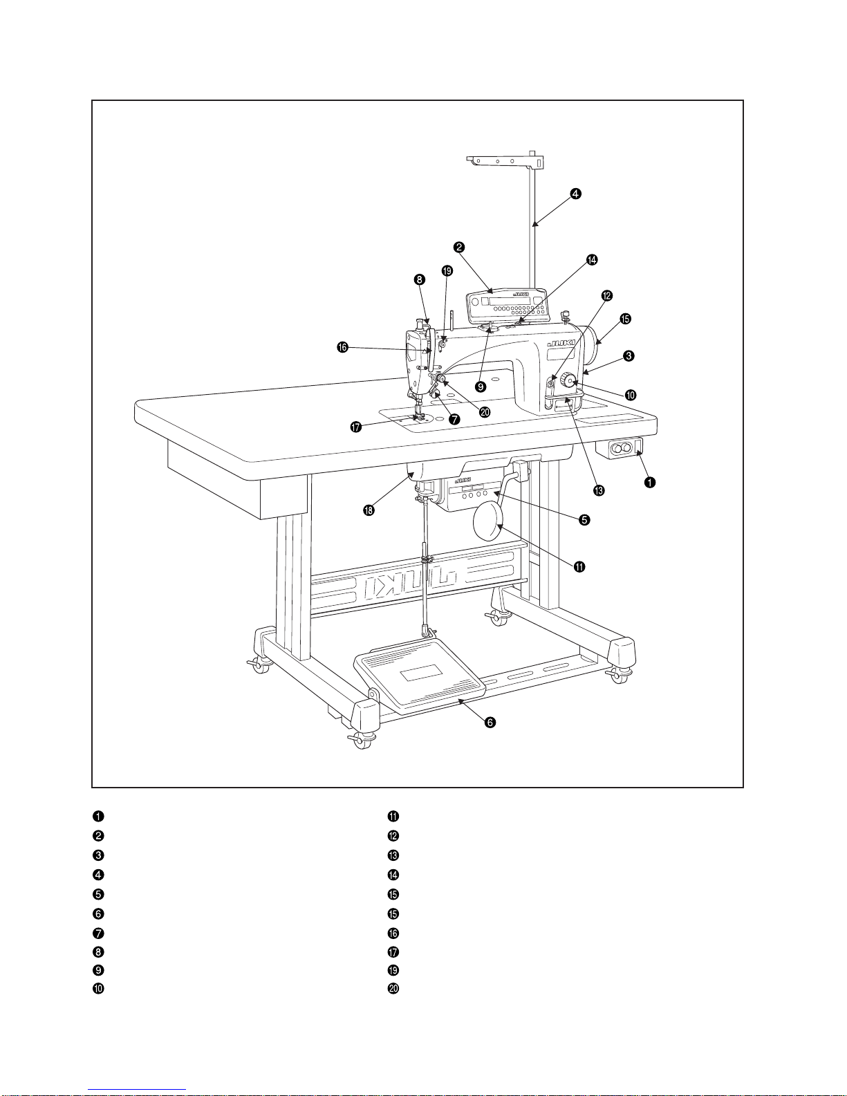
2. Name of each component ............................................................................ 2
3. Standard adjustment .................................................................................... 4
(1) Feed dog height and gradient ...................................................................................4
(2) Timing for the needle and the inner hook ................................................................6
(3) Needle and feed timing ..............................................................................................8
(4) Feed locus and phase ..............................................................................................10
(5) Bobbin insertion .......................................................................................................12
1) Bobbin case with idling prevention spring ..................................................................................12
(6) Adjustment of inner hook presser position ...........................................................14
(7) Lubrication ................................................................................................................16
1) Method of lubrication .....................................................................................................................16
2) Method of lubrication to the oil tank.............................................................................................18
3) Method of oil drainage from the oil tank ......................................................................................18
4) Cleaning of the oil filter..................................................................................................................20
5) Oil in the gear box ..........................................................................................................................22
6) Placement/displacement of the gear box cover ..........................................................................22
7) Cautions for gear box cover oil during transportation ...............................................................22
8) Adjustment of hook oil quantity....................................................................................................24
9) Hook oil adjustment procedures...................................................................................................24
10)Essentials for hook oil adjustments .............................................................................................24
11) Replacement of the hook shaft oil wick .......................................................................................24
(8) Adjustment of the amount of feeding .....................................................................26
1) Adjustment of forward feed stitch length.....................................................................................26
2) Adjustment of reverse feed stitch length (manual) .....................................................................26
3) Adjustment of reverse feed stitch length (motor-power)............................................................26
4) Optional switch ...............................................................................................................................28
5) Adjustment of normal/reverse stitching.......................................................................................30
6) Adjustment of Feed 0 .....................................................................................................................30
1. Method by removing the gear box cover (standard adjustment) .................................................30
2. Method without removing the gear box cover (fine adjustment).................................................32
7) Adjustment of the feed dial section ..............................................................................................34
8) Adjustment of the reverse feed solenoid .....................................................................................36
9) Adjustment of feed changing shaft balancer arm (asm) positioning ........................................36
(9) Adjustment of the presser lifter ..............................................................................38
1) Adjustment of the presser pressure .............................................................................................38
2) Adjustment of thread release changeover ...................................................................................38
3) Adjustment of the micro-lifter .......................................................................................................40
4) Adjustment of the micro-lifter unit (available separately) ..........................................................40
(10) Adjustment of needle stop position........................................................................42
1) Adjustment of upper stop position (Stop position after thread trimming) ................................42
2) Adjustment of lower stop position ................................................................................................42
(11) Thread trimming unit................................................................................................44
1) Standard timing for the thread trimming cam..............................................................................44
1. Method of confirmation ................................................................................................................45
2. Method of adjustment ..................................................................................................................45
2) Correct position of the moving knife ............................................................................................46
1. Extreme backward position .........................................................................................................47
2. Initial position...............................................................................................................................47

3) Adjustment to the moving knife position .....................................................................................48
1. Standard adjustments..................................................................................................................49
2. Specific adjustment .....................................................................................................................49
4) Correct position of the counter knife............................................................................................50
5) Adjustment of rise of the second thread tension disc................................................................52
1. How to check the amount of rise of the second thread tension disc ...........................................53
2. How to adjust the amount of rise of the second thread tension disc ...........................................53
6) Adjustment of the fixed knife blade tip.........................................................................................54
7) Replacement of the moving knife .................................................................................................56
8) Replacement of the knife thread guide.........................................................................................58
9) Adjustment of the picker................................................................................................................60
1. Method of confirmation ................................................................................................................61
2. Method of standard adjustments (Adjustment of clearance) .......................................................61
3. Method of standard adjustments (Adjustment of tip position)......................................................61
10)Adjustment of the drive arm stopper............................................................................................62
11) Replacement of the knife unit........................................................................................................64
(12) Adjustment of the wiper (DDL-9000A- -WB/OB).............................................66
(13) Adjustment of feed lever pressure..........................................................................68
(14) Adjustment of external parts ...................................................................................70
1) Adjustment of the pulley cover .....................................................................................................70
2) Clearance of the hand wheel .........................................................................................................70
3) Adjustment of the bobbin winder unit ..........................................................................................72
1. Replacement of the bobbin friction wheel....................................................................................73
2. Adjustment of the bobbin winder driver wheel position ...............................................................73
4. Maintenance ................................................................................................ 74
(1) Oil quantity check.....................................................................................................74
(2) Application of appropriate grease ..........................................................................74
1) Needle bar lower bushing (DDL-9000A-M , A-DS Specification) .............................................74
2) Feed bar mechanisms ....................................................................................................................76
3) Face plate mechanism ...................................................................................................................78
(3) Lubrication mechanism configuration and adjustments
(DDL-9000A-SS, SH, MA, MS) ..................................................................................80
(4) Thread take-up lever mechanism............................................................................82
(5) Replacement of the motor .......................................................................................84
(6) Replacement of the timing belt ...............................................................................84
5. Screws for attachment and positions of external parts.......................... 86
6. Dry hook....................................................................................................... 87
(1) Cautions when a dry hook is used..........................................................................87
(2) Replacement of the dry hook ..................................................................................87
7. Head section and control circuit connection diagram............................ 88
8. Air blow type hook cooling unit (available separately) ........................... 89
9. Troubles and corrective measures ........................................................... 90
(1) Mechanical parts.......................................................................................................90
(2) Sewing conditions ....................................................................................................96
10. Drawing of the table................................................................................ 107

– 1 –
DDL-9000A-SS DDL-9000A-SH DDL-9000A-MA DDL-9000A-MS DDL-9000A-DS
Minute-quantity lubrication Minute-quantity lubrication
Semi-dry *4 Semi-dry Dry
For standard materials
For heavy-weight materials For light-weight materials
For standard materials For standard materials
1 Max. sewing speed 5000rpm *1 4500rpm *1 5000rpm *1, *4 4000rpm
2 Max. stitch length Difference of stitch length 5 mm Difference of stitch length 5 mm
3 Needle bar stroke 30.7mm 35mm 29mm 30.7mm 30.7mm
4
Take-up lever stroke (standard value)
110mm 108mm 110mm 110mm 110mm
5 Thread trimming method Horizontal type
6 Lower bobbin winder unit Built-in, top surface of machine head (with bobbin thread holding plate)
7 Wiper (only for WB specification) Electromagnetic side wiper
8 Automatic reverse feeding unit Built-in electromagnetic type
Plate (needle bar) Oil wick lubrication Grease lubrication
9 Hook Plunger pump type No lubrication
Gearbox Sealed type
Plate (needle bar) With oil tank (capacity: 180 ml) No lubrication
Hook With oil tank (capacity: 180 ml) No lubrication
JUKI New Defrix Oil No. 1 or Exclusive grease
Plate (needle bar) JUKI Machine Oil No. 7 JUKI Grease A (product No.: 40006323) 20g contained
(equivalent to ISO VG7) *2
JUKI New Defrix Oil No. 1 or JUKI Machine Oil No. 7
(equivalent to ISO VG7) *2
Gearbox JUKI New Defrix Oil No.2 (equivalent to ISO VG32) *3
12 Lifting amount of presser Presser lifter lever: 5.5 mm/By knee: 15 mm/AK: 8.5 mm
DB x 1 (#11) DB x 1 (#21) DB x 1 (SF#9) DB x 1 (#11) DB x 1 (#11)
#9 to 18 #20 to 23 #8 to 11 #9 to 18 #9 to 18
134 (Nm75) 134 (Nm130) 134 (Nm65) 134 (Nm75) 134 (Nm75)
Nm65 to 110 Nm125 to 160 Nm60 to 75 Nm65 to 110 Nm65 to 110
Sewing space width
300mm
14 Dimensions
Sewing space height
137mm
Bed size 178mmX517mm
15 Machine head weight 43.5kg, 46.5kg (with AK)
16 Power consumption SC-810 : 320VA, SC-910N : 350VA
17
Working temperature and humidity
Temperature: 5 °C to 35°C, humidity: 35% to 85% (No dew condensation permissible)
18 Supply voltage and frequency Rated voltage ±10%, 50/60Hz
1. Specifications
Model
Item
10 Oil supply
No.
11
13 Needle
Hook
*1: The machine shall be used at maximum of 4,000 rpm for the stitch of 4 mm. The reverse feeding length is set to 4 mm at shipment.
If more than 4 mm of the reverse feeding length is required, cancel the default setting before use. Refer to [3.- (8) –8) Adjustment of
the reverse feed solenoid].
*2: JUKI New Defrix Oil No. 1 or JUKI Machine Oil No. 7 (equivalent to ISO VG7)
*3: JUKI New Defrix Oil No.2 (equivalent to ISO VG32)
*4: When a version of the DDL-9000A-MA specification is used over a speed of 4,000rpm, the presser pressure adjusting spring
should be replaced for the standard type.
No lubrication
Oil to be used
(grease)
Lubrication
system
Difference of stitch
length 4 mm

– 2 –
2. Name of each component
Power switch Knee lifter
Operation panel (CP-170 or IP-110) Oil filler port (except for DDL-9000A-DS)
Pulley cover Feed lever
Thread stand Minute adjustable presser lifting screw
Control box (SC-810 or SC-910N) Hand wheel
Operation pedal Take-up lever cover
One-touch type reverse feed button Finger guard
Wiper Under cover
Bobbin winder unit 1st thread tension
Stitch dial 2nd thread tension

– 3 –
Power switch
This switch turns on and off the power to the head unit motor, electric components, and operation panel.
Operation panel (CP-170 or IP-110)
This panel allows users to conduct the settings of automatic reverse stitching, head sewing, sewing speed, and
more.
Pulley cover
This cover protects the machine head motor.
Thread stand
Control box (SC-810 or SC-910N)
The box contains the circuit that controls the head unit and motor, the output circuit that operates each output
(the thread trimming solenoid, back solenoid, wiper solenoid, etc.), the pedal sensor that detects the pedal
operation, and the power circuit that performs each function.
Operation pedal
This pedal allows users to conduct machine speed control, thread trimming, presser lifting motion (only for AK-
138), and more by depressing the front or back part of the pedal.
One-touch type reverse feed button
This button allows users to conduct reverse stitching.
Wiper
The wiper moves the needle from the sewing material after thread trimming under control of the wiper signal
from the control box.
Bobbin winder unit
This unit is integrated into the head unit.
Stitch dial
This dial adjusts the front feeding amount.
Knee lifter
Oil filler port (except for DDL-9000A-DS)
This port is used for lubrication to the hook. (except for DDL-9000A-DS)
Feed lever
This lever allows users to conduct reverse stitching.
Minute adjustable presser lifting screw
Hand wheel
Take-up lever cover
This cover prevents users from touching the take-up lever.
Finger guard
This guard prevents users (mainly thumb and fingers) from touching the needle.
Under cover
1st thread tension
2nd thread tension

– 4 –
3. Standard adjustment
(1)Feed dog height and gradient
Standard feed dog height (Feed dial graduation 0)
0.8mm : DDL-9000A-S, DDL-9000A-A
1.2mm : DDL-9000A-SH
Standard feed dog gradient
The engraved marker dot on the feed bar shaft is adjusted by a feed dog of relevant standard.
Shipped feed dog •B1613012I00 • 23614506
(A- S, A-MA) (A- S)
•D1613155W00 • 11403003
(A-MA) (A-SH)
Engraved marker dot
position on the horizontal
feed bar shaft
9000A- S, 9000A- A : 0.8mm
9000A-SH : 1.2mm
ab
A
B
a
b
a
b
A
B
Standard Adjustment

– 5 –
1. Set the amount of feeding (feed dial graduation) at 0.
2. Loosen the setscrew of the vertical feed bracket shaft and the
setscrew of the horizontal feed bracket shaft .
3. The feed dog height and gradient are changed when both shafts of
the vertical feed bracket shaft and the horizontal feed bracket
shaft are turned by means of a screwdriver.
4. After adjustments, firmly tighten the screws that have been loosened.
(Screw tightening should be done under the condition that the
setscrews and are pushed against the vertical feed bracket
shaft and the horizontal feed bracket shaft .)
(Cautions) 1. In regard to the locus of standard feeding, the throat
plate and the feed dog rise almost horizontally when
the throat plate rises.
2. The direction of the engraved marker dots for the
vertical feed bracket shaft and the horizontal feed
bracket shaft should be adjusted on the right side
(operator side).
3. If there is rattle in the vertical feed bracket shaft
and the horizontal feed bracket shaft , this can be
a cause of unusual sound and improper linearity.
o If the gradient of the feed dog is
adjusted for either shaft only, the
feed dog height may be changed.
Adjustments are needed for both
shafts in all cases.
o According to the shaft adjusting
position, the position of feed dog
motion may be shifted.
In such a case, loosen the
tightening screw of the X feed
arm to adjust the position of
motion.
oAccording to the result of feed dog
height or gradient adjustments,
there is possibility of interference
with the thread trimmer unit.
oWhen the feed dog height is set
above the standard level, the
feeding power is improved.
Instead, there can be problems of
presser jumping at high speed and
flaws in light materials.
oIf the feed dog height is too much,
a return will be given to the front
side (Section C) of the feed dog.
As a result, the behavior of
material feeding may be affected.
If the height has to be increased
for an unavoidable reason, the
amount of return can be reduced
by adjusting the gradient of the
feed dog to raise its tip.
0.8mm DDL-9000A- S, A
1.2mm DDL-9000A-SH
C
Adjustment Procedure Results of Improper Adjustment

– 6 –
(2)Timing for the needle and the inner hook
C
D
A
B
B
0.04 to 0.1mm
A
Standard Adjustment
Lubricated hook K
Part No. : 23621303

– 7 –
1. Turn the flywheel until the needle bar comes to its lowest position,
and loosen the needle bar connecting setscrew .
2. Determine the needle bar height.
Adjust the engraved marker line (marker line Afor the DB needle
and marker line Cfor the DA needle) of the needle bar to the
lower end of the needle bar lower metal and tighten the needle
bar connecting setscrew . (Be careful not to tighten the needle
bar connecting setscrew too much.)
3. Determine the mounting position of the hook .
Turn the three hook setscrews in the direction of flywheel forward
revolutions to raise the needle bar. In this direction, adjust the
engraved marker line (marker line Bfor the DB needle and marker
line Dfor the DA needle) to the lower end of the needle bar lower
metal .
4. In this state, adjust the blade point of the inner hook to the center
of the needle so that a clearance of 0.04 to 0.1mm (goal value) is
secured between the needle and the hook . Since then, firmly
tighten the three hook setscrews.
(Cautions) 1. If this clearance is too small, the blade point of the
hook may be damaged.
2. Too much clearance may give rise to stitch skipping.
<Information about the dry hook>
A dry hook (RP hook) is employed for the DDL-9000A-DS type.
For replacement, use the part numbers specified below.
The hook part numbers come in two types according to the specifications.
22890206 (without the needle guard)
22890404 (with the needle guard)
22890305 (22890206 with special surface treatment)
(Cautions) The dry hook (RP hook) tends to collect thread chips
and material dust. This can cause malfunction or
defective stitches. Periodic cleaning is required.
<Lubricated hook K: Available separately>
This is a hard blade point hook with a needle holder applicable to needle
size #9 (#65).
Where a thin needle has to be used for reasons of sewing processes,
this type of hook is applicable to the prevention of stitch skipping and
needle breakage.
Adjustment Procedure Results of Improper Adjustment
About the needle bar
Specifications Part No. Needle shank
DDL-9000A-S , A-DS 22886907 1.8mm ø1.64
DDL-9000A-S , A-DS 22887009 1.8mm ø2.02
DDL-9000A-SH 40061767 2.3mm ø2.04
Amount of
looper return

– 8 –
(3) Needle and feed timing
Vertical feed cam phase
(engraved marker line position)
0
±
1mm
Standard Adjustment
Models Other than DDL-9000A-SH DDL-9000A-SH
Vertical feed cam engraved marker line 0°+10°
Feed dial graduations 3 4
In a moment when the feed dog is positioned below the upper
surface of the throat plate, the upper end (A-SH: lower end) of
the needle hole shall be 0±1mm from the upper plane of the
throat plate.
Needle and feed timing
A-SHOther than A-SH
Needle and feed timing
Standard Adjustment

– 9 –
1. Adjust the feed dial graduations.
o DDL-9000A-SH: Feed dial graduation 4
oOther than DDL-9000A-SH: Feed dial graduation 3
2. Let the sewing machine fall down and check the engraved marker
line position of the vertical feed cam .
oDDL-9000A-SH: +10°( )
oOther than DDL-9000A-SH: 0°( )
For adjustments, loosen two vertical feed cam setscrews and adjust
the cam to the engraved marker line .
(Cautions) The angle of the engraved marker line graduation 1
denotes 10°.
3. Loosen two lower sprocket screws .
4. At the feed dog lowering timing (position where the upper end of the
feed dog coincides with the upper plane of the throat plate), fix the
vertical feed cam and slowly turn the flywheel in forward direction
until the upper end of the needle hole coincides with the upper plane
of the throat plate.
*In cases other than the DDL-9000A-SH, coincidence of the
engraved marker dot of the pulley cover with the engraved
marker dot of the flywheel can be regarded as the standard for
needle hole upper end lowering.
When coincidence is confirmed, tighten two lower sprocket screws
.
(Tightening torque for reference: 4.5N•m)
5. Adjust the thread trimmer cam timing.
Refer to [3.–(11) Thread trimmer unit -1) Thread trimmer cam
standard timing].
6. Adjust the hook timing.
Refer to [(2) Needle and hook timing].
(Cautions) When the above-mentioned adjustments are finished,
operate the sewing machine and examine whether any
unusual sound or torque is generated or the thread
trimmer unit works normally.
oWhen tightening the two vertical
feed cam setscrews , this work
should be done while a good cen-
tering is secured.
Otherwise, there will be adverse
torque or unusual sound generation,
or abnormal wear may be caused.
Adjustment Procedure Results of Improper Adjustment

– 10 –
(4) Feed locus and phase
1. Timing standard 2. Timing fast 3. Timing slow
Standard Adjustment

– 11 –
[Feed locus change]
By adjusting the phase of the vertical feed cam , it is possible to change
the up/down timing for the feed locus and needle.
Adjustments can be carried out with two setscrews .
1. Timing standard
The vertical feed shaft engraved marker line coincides with the
vertical feed cam engraved marker line at 0°.
Refer to [3.-(3) Needle and feed timing].
2. Timing fast
If you adjust the vertical feed shaft engraved marker line to the
vertical feed cam engraved marker line and the minus side, the
vertical feed timing is hastened against horizontal feed.
(Also hastened against the needle)
(Cautions) Adjustments should be done within –20°(2
graduations).
3. Timing slow
If you adjust the vertical feed shaft engraved marker line to the
vertical feed cam engraved marker line and the plus side, the
vertical feed timing is delayed against horizontal feed.
(Also delayed against the needle)
(Cautions) Adjustments should be done within +20°(2
graduations).
(Cautions) 1. When timing of the vertical feed cam is changed,
the feed timing is also changed against the needle.
When the timing is adjusted, re-adjustment is
required in accordance with [(3) Needle and feed
timing].
2. The angle of the engraved marker line graduation 1
denotes 10°.
oWhen tightening the two setscrews
of the vertical feed cam , this
work should be done while a good
centering is secured.
Otherwise, there will be adverse
torque or unusual sound generation,
or abnormal wear may be caused.
oSince the motion in horizontal
direction is reduced at the
beginning of feeding, the material
cloth is fed assuredly by the effect
of creep reduction.
oFeeding force is reduced around
the end of feeding because the
feed dog lowers faster.
oThe motion becomes moderate at
the beginning of feeding, thus
making the material cloth biting
worse.
oLight materials tend to be less
damaged.
oThe material cloth is fed assuredly
at the end of feeding. Thanks to
the leading effect, puckering tends
to be improved.
Adjustment Procedure Results of Improper Adjustment

– 12 –
(5) Bobbin insertion
1) Bobbin case with idling prevention spring
(Drawing is for 11038700.)
B
A
C
oFor the bobbin case with idling prevention spring
(1) (2)
(3) (4)
Ear
Change the height.
0.3
±
0.2mm
Bobbin revolution
Standard Adjustment

– 13 –
1. Hold the bobbin so that it turns to the right and insert it in the bobbin
case. (See Drawing.)
2. Pass the thread through the threading port Aof the bobbin case.
When the thread is pulled in the direction of C, it can be pulled
toward the threading port Bpassing beneath the thread tension
spring.
3. Examine if the bobbin turns in the direction of the arrow when the
bobbin thread is pulled.
Part name MS, SS DS SH MA
Bobbin case 22896252 11038759 11038759
11038700
Bobbin
D1837555
BAAA
D1837555
BAOB
B9117552A00
(Made of aluminum) B9117012000
(Made of iron)
About the standard part numbers (DDL-9000A- )
1) Bobbin case with idling prevention spring
The DDL-9000A Series employs the bobbin case with an idling prevention spring.
Adjustments of idling prevention spring tension can be carried out in the procedures below.
If bobbin idling occurs, increase the idling prevention spring tension
When the bobbin runs idle Increase the tension of the idle-prevention spring.
When the thread is not well tightened Decrease the tension of the idle-prevention spring.
* Adjustment of idling prevention spring tension
(1) Insert an old needle as illustrated and remove the spring by lifting it up.
(Suggestion: Use the thumb to prevent the spring from popping out.)
(2) The spring tension can be changed by changing the height of the arch-shaped section of the spring.
(Make sure not to permit the free end of the spring to come out of the bobbin case.)
(3) Firstly, set the ear and insert the needle. Then, settle the ear is the state that the center part of the
spring is lifted.
(4) When a bobbin case with an idling prevention spring is used, it should be inserted in the winding direction
as illustrated.
(Unevenness in sewing at high or low speed)
When sewing seems to be too tight Adjust the bobbin thread tension and the idling
at low speed: prevention spring tension to be strengthened.
When sewing seems to be too weak Adjust the bobbin thread tension and the idling prevention
at low speed: spring tension to be weakened.
*If there is a problem of bobbin idling or uneven sewing at high or low speed, use of a bobbin case with an
idling prevention spring is effective.
oIf the direction of clockwise wind-
ing is adopted, variation is less-
ened possibly caused by a change
in the amount of bobbin thread.
Adjustment Procedure Results of Improper Adjustment
Bobbin case with idling
prevention spring
B9117552A00
(Made of aluminum)

– 14 –
(6)Adjustment of inner hook presser position
Other than DDL-9000A-SH DDL-9000A-SH
Inner hook presser 40032052 40037405
Needle entry
About the standard part numbers
Standard Adjustment
Inner hook
*As seen from above, after removing
the throat plate

– 15 –
1. The front and rear positions of the inner hook presser can be
adjusted by means of the setscrew .
[Standard adjusting value]
Fasten the needle entry section by means of the setscrew so
that it is located closer to the shoulder section toward the front side
from the center of the embossed part in the inner hook presser .
oIf the embossed part of the inner
hook presser has any flaw, this
can be a cause of thread break-
age or uneven sewing.
In such a case, the damaged part
shall be replaced with a new one.
o If the inner hook presser is
positioned inadequately, an extra
tension is exerted when the thread
comes out of the embossed part.
This can be a cause of shrinkage
errors.
Adjustment Procedure Results of Improper Adjustment

– 16 –
(7)Lubrication
1) Method of lubrication
Float
Float
Standard Adjustment
DDL-9000A-S
(Specification for minute-quantity
lubrication)
DDL-9000A-M
(Specification for semi-dry items)
DDL-9000A-DS
(Specification for dry items)
Other manuals for DDL-9000A
2
Table of contents
Other JUKI Sewing Machine manuals

JUKI
JUKI LBH-772NV-1 User manual

JUKI
JUKI MO-50e User manual

JUKI
JUKI LU-1508N User manual

JUKI
JUKI MF-7500 Series User manual

JUKI
JUKI LBH-1700 Quick start guide

JUKI
JUKI DU-1481 Series User manual

JUKI
JUKI LU-1520N-7 User manual

JUKI
JUKI MB-1800 series User manual

JUKI
JUKI Union Special MFC-7406 User manual

JUKI
JUKI HZL-80 series User manual

JUKI
JUKI DDL-8100e User manual

JUKI
JUKI MC-35 User manual

JUKI
JUKI HZL-30Z User manual

JUKI
JUKI IP-110 Type F User manual

JUKI
JUKI TL-98Q User manual

JUKI
JUKI LH-3126F Installation guide

JUKI
JUKI DU-1181N User manual

JUKI
JUKI MO-654DE/654 User manual

JUKI
JUKI MO-2800 User manual

JUKI
JUKI AMS-210E/IP-410 User manual