(4)
Unless
the
bottom
surface
of the
presscr
foot ® and the
upper
surface
of the
throat
plate are
snuggly
contacting each other when the feed dog is lowered, the stitches may
become curved and the chain-off thread stitching of double chain stitch can not be
performed
well.
Loosen
the
presser
foot
hinge
screw © and adjust so that the bottom
surface
of the
presser
foot ® drops little to right
when
the
presser
foot is
raised
and
when the
presser
foot is lowered, the bottom
surface
snuggly
contacts the throat plate
surface. (In case of MO-816)
(Note)
*
When
sewmg
light
weight
materials,
if
the
pressing
pressure
is
too
strong
or
the
protrusion
amount
of
the
feed
dog
is
too
great,
shrink
stitch-
irig
or
damage
to
the
sewing
cloth
may
result.
On
the
contrary,
if
the
pressure
is
too
weak
or
the
protrusion
of
the
feed
dog
is
too
small,
pitch
flaw
or
contracted
stitches
might
result.
Be
sure
to
make
correct
adjustment.
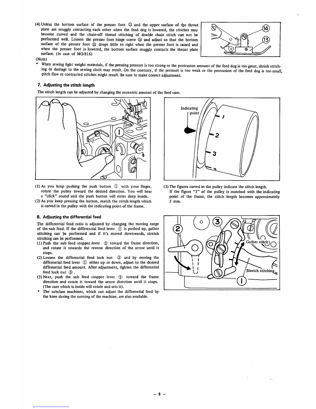
7. Adjusting
the
stitch length
The stitch length can be adjusted by changing the eccentric amount of the feed cam.
\i
/
csT
Indicating
(1)As you keep
pushing
the push button
(T)
with your
finger,
rotate
the
pulley
toward
the desired direction.
You
will
hear
a
"click"
sound and the push
button
will
enter
deep inside.
(2) As you keep pressing the
button,
match the stitch length which
is carved in the pulley with the indicating point of the frame.
(3) The figures carved in the pulley indicate the stitch length.
If the figure
"3"
of the pulley is matched with the indicating
point of the frame, the stitch length becomes approximately
3
mm.
8.
Adjusting
the
differential
feed
Tlie differential feed
ratio
is
adjusted
by changing
the
moving range
of the-sub feed. If the differential feed lever ® is pushed up, gather
stitching
can be
performed
and
if
it's
moved
downwards,
stretch
stitching
can be
performed.
(1)Push
the
sub
feed
stopper
lever (2)
toward
the frame direction,
and
rotate
it
towards
the
reverse
direction
of
the
arrow
until
it
stops.
(2) Loosen the differential feed lock
nut
(3) and by moving the
differential feed lever ® either up or down, adjust to the desired
differential feed
amount.
After
adjustment,
tighten
the differential
feed
lock
nut
(3).
(3)
Next,
push
the
sub
feed
stopper
lever (2)
toward
the
frame
direction
and
rotate
it
toward
the
arrow
direction
until
it
stops.
(The
cam
which
is
inside
will
rotate
and
sets
it).
*
The
subclass machines, which can adjust
the
differential feed by
the knee during the running of the machine, are also available.
- 8 -
(D
n
Gather
stitcl^^^
Stretch
stitching