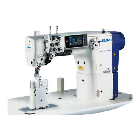
JUKI PS-700 User manual

PS-700
INSTRUCTION MANUAL

i
CONTENTS
I. MECHANICAL SECTION ........................................................................ 1
1. SPECIFICATIONS..................................................................................................................... 1
2. CONFIGURATION..................................................................................................................... 2
3. INSTALLATION ......................................................................................................................... 3
3-1. Installing the extension plate and the power switch ..................................................................3
3-2. Installing the bobbin winder device .............................................................................................4
3-3. Installing the panel.........................................................................................................................6
3-4. Installing the thread stand ............................................................................................................6
3-5. Installing the X-axis feed mechanism ..........................................................................................7
3-6. Attaching and removing the hook ................................................................................................8
3-7. Installing the auxiliary table..........................................................................................................9
3-8. Installing the air hose ....................................................................................................................9
3-9. Precautions to be taken when installing the machine..............................................................10
3-10. Cautions for the compressed air supply (source of supply air) facility ................................. 11
4. PREPARATION OF THE SEWING MACHINE........................................................................ 12
4-1. Lubricating method and check of the oil quantity....................................................................12
4-2. Attaching the needle....................................................................................................................13
4-3. Threading the machine head ......................................................................................................13
4-4. Bobbin replacement procedure..................................................................................................14
4-5. Adjusting the thread tension ......................................................................................................15
4-6. Adjusting the thread take-up spring and the thread breakage detector plate .......................16
4-7. Adjusting the thread take-up stroke...........................................................................................16
4-8. Needle-to-hook relationship........................................................................................................17
4-9. Adjusting the height of the intermediate presser .....................................................................17
4-10. Adjusting the stroke of the intermediate presser .....................................................................18
4-11. Adjusting the height of disc presser and the presser foot pressure ......................................19
4-12. Adjusting the counter knife.........................................................................................................20
4-13. How to conrm the amount of oil (oil splashes) in the hook...................................................21
4-14. Adjusting the amount of oil in the hook.....................................................................................22
4-15. Direction of rotation of the hand pulley .....................................................................................23
4-16. Installing and adjusting the thread separation plate ................................................................23
4-17. Adjusting the angle of air blower................................................................................................24
5. MAINTENANCE OF SAWING MACHINE............................................................................... 25
5-1. Replenishing the designated places with grease .....................................................................25
5-2. Draining waste oil ........................................................................................................................26
5-3. Use of an air gun..........................................................................................................................27
5-4. Cleaning the hook section ..........................................................................................................27
5-5. Other precautions ........................................................................................................................27
5-6. How to remove the face plate .....................................................................................................28
5-7. Troubles and corrective measures (Sewing conditions)..........................................................29
6. PRECAUTIONS....................................................................................................................... 30
6-1. Standard specication of the templates....................................................................................30
6-2. Sewing with large pitches ...........................................................................................................30
6-3. Reverse feed stitching.................................................................................................................31
6-4. Condensation stitching ...............................................................................................................31
6-5. Groove on the template...............................................................................................................31

ii
7. OPTIONAL .............................................................................................................................. 32
7-1. Setting the needle cooler device ................................................................................................32
7-2. Setting the deviation amount of the pen pricking device ........................................................33
7-3. Setting the bobbin thread remaining amount detecting device ..............................................36
8. CONSUMABLE PARTS LIST ................................................................................................. 37
II. OPERATION SECTION (WITH REGARD TO THE PANEL) ................ 38
1. PREFACE................................................................................................................................ 38
1-1. Kind of sewing data handled with panel....................................................................................38
1-2. Using the sewing data with PS-700............................................................................................38
1-3. Folder structure of the media .....................................................................................................38
1-4. USB port........................................................................................................................................39
2. PANEL..................................................................................................................................... 40
2-1. Name of each section of panel ...................................................................................................40
2-2. Explanation of the operation panel ............................................................................................41
2-2-1. Changing over the display language ...............................................................................41
2-2-2. Main screen P1...................................................................................................................42
2-2-3. Main screen P2...................................................................................................................42
2-2-4. Menu screen.......................................................................................................................42
2-2-5. Explanation of the main screen P1 ..................................................................................43
2-2-6. Explanation of the main screen P2 ..................................................................................45
2-2-8. Changing over the screen display style ..........................................................................48
2-3. Basic operation of the operation panel and the basic operation for sewing .........................49
2-4. Explanation of operation functions............................................................................................51
2-4-1. Reading sewing patterns ..................................................................................................51
(1) Displaying the sewing pattern read mode screen..........................................................51
(2) Selecting the data storage area from which a sewing pattern is read (Internal
memory or the USB thumb drive).....................................................................................53
(3) Selecting and displaying a sewing pattern .....................................................................53
(4) Displaying the folders in the USB thumb drive ..............................................................54
2-4-2. Storing sewing patterns....................................................................................................55
(1) Displaying the sewing pattern storage mode .................................................................55
(2) Setting the name and number of a sewing pattern ........................................................55
(3) Initialization and backup of parameters ..........................................................................56
2-4-3. Enlargement / reduction of sewing patterns...................................................................57
2-5. Operating the barcode reader.....................................................................................................59
2-5-1. Explanation of the barcode reader...................................................................................59
2-5-2. Method to set the barcode reader ....................................................................................59
3. MEMORY PARAMETER LIST ................................................................................................ 61
4. ERROR CODE LIST................................................................................................................ 63
5. MESSAGE LIST ...................................................................................................................... 65

– 1 –
1. SPECIFICATIONS
I. MECHANICAL SECTION
1 Sewing area X (lateral) direction : 1,200 mm × Y (longitudinal) direction : 700 mm
2 Max. sewing speed 3,000 sti/min (When stitching pitch is 3 mm or less)
3 Settable stitch length 0.1 to 12.7 mm
4Feed motion of feeding frame Intermittent feed (2-shaft drive by stepping motor)
5 Needle bar stroke 39.8 mm
6 Needle Organ needle DB × 1 #9 to 16
7 Thread Filament #50, Span #30
8 Lift of disc presser Max. 13 mm
9 Intermediate presser stroke 4 mm (Standard) (4 to 8.7 mm)
10 Lift of intermediate presser 23 mm
11 Hook Double-capacity full-rotary hook
12 Lubricating oil JUKI CORPORATION GENUINE OIL 7 (Supplied by oiler)
13 Memory of pattern data Main body : Max. 999 patterns (Max. 60,000 stitches/pattern)
External media : Max. 999 patterns (Max. 60,000 stitches/pattern)
14 Temporary stop facility Used to stop machine operation during a stitching cycle.
15 Enlarging / Reducing facility Allows a pattern to be enlarged or reduced on the X axis and Y axis inde-
pendently when sewing a pattern.
Scale : 10 to 400 % (0.1 % steps)
16 Enlarging / Reducing method Pattern enlargement / reduction can be done by increasing / decreasing
either stitch length or the number of stitches. (Increasing/decreasing
stitch length only can be performed when pattern key is selected.)
17 Max. sewing speed limitation 200 to 3,000 sti/min (100 sti/min steps)
18 Pattern selection facility Pattern No. selection method
(Main body : 1 to 999, External media : 1 to 999)
19 Bobbin thread counter UP/DOWN method (0 to 99,999)
20 Sewing counter UP/DOWN method (0 to 99,999)
21 Memory back-up In case of a power interruption, the pattern being used will automatically
be stored in memory.
22 2nd origin setting facility Using jog keys, a 2nd origin (needle position after a sewing cycle) can be
set in the desired position within the sewing area. The set 2nd origin is
also stored in memory.
23 Sewing machine motor Servo-motor
24 Dimensions 1,870 mm (W) × 2,130 mm (L) × 1,410 mm (H) (Excluding thread stand)
25 Mass (gross mass) 722 kg
26 Power consumption 255.3 VA
27 Operating temperature range 5 to 35 ˚C
28 Operating humidity range 35 to 85 % (No dew condensation)
29 Storage temperature range -20 to 60 ˚C
30 Storage humidity range 10 to 85 % (No dew condensation, 85 % applies to the case where the
temperature is 40 ˚C or lower)
31 Line voltage Single phase 220 to 240 V
32 Air pressure used 0.5 to 0.55 MPa (Max. 0.7 MPa)
33 Needle highest position stop
facility
After the completion of sewing, the needle can be brought up to its high-
est position.
34 Noise - Equivalent continuous emission sound pressure level (LpA) at the work-
station :
A-weighted value of 76.0 dB ; (Includes KpA = 2.5 dB) ; according to
ISO 10821- C.6.2 -ISO 11204 GR2 at 2,500 sti/min.

– 2 –
Air control device
2. CONFIGURATION
❶Machine head
❷Table
❸X-axis feed mechanism
❹Y-axis feed mechanism
❺Cassette clamp device
❻Operation panel
❼Air control box
❽Electrical control box
❾Power switch (also used as the emergency
stop switch)
Thread stand
Bobbin winder device
❶
❷
❸
❹
❻
❼
❾
❺
❽

– 3 –
3. INSTALLATION
3-1. Installing the extension plate and the power switch
1. Do not lean over extension plate ❶
or push it by hand so as to prevent
bodily injury due to abrupt lowering of
extension plate ❶.
2. When returning extension plate ❶
to its raised position from the tilted
position, take care not to allow your
hands and ngers to be caught in it.
3. When loosening toggle clamp ❼,
slowly lower it while supporting
extension plate ❶by hand. Never let
the toggle clamp fall freely in order to
prevent bodily injury.
4. Do not place any heavy object on the
extension table sections.
1) Insert pin Aof positioning plate ❷into the hole
in extension plate ❶. Then, secure the pin with
hexagon socket head screw ❸and washer ❹.
2) Attach toggle clamps ❼respectively to left exten-
sion plate ❺and right extension plate ❻. Then,
secure them respectively with hexagon socket
head screw ❸and washer ❹.
3) Firstly, detach power switch (asm.) from main
table ❾. Align the position of left extension plate
❺and right extension plate ❻with the position
of main table ❾. In this state, secure the exten-
sion plates and the main table using table support
bracket ❽and bobbin winder device mounting
plate with hexagon socket head screws ❸and
washers ❹. At this time, carefully align the outer
peripheries of left extension plate ❺and of right
extension plate ❻with the outer periphery of
main table ❾and adjust them so that no clear-
ance is provided between the extension plates
and the main table.
4) Once extension plate ❶and main table ❾are
correctly positioned, x extension plate ❶with
hinge using hexagon socket head screws ❸
and washers ❹. At this time, take care not to
provide any clearance between extension plate
❶and main table ❾. In addition, make sure that
extension plate ❶can be normally opened/closed
without getting stuck with the related parts.
5) Lift extension plate ❶until positioning plate ❷
comes in contact with left extension plate ❺and
right extension plate ❻. In this state, lock toggle
clamp ❼. At this time, adjust clamp height of
toggle clamp ❼. If the clamp height is too low,
extension plate ❶drops, or if it is too high, toggle
clamp ❼cannot be closed. So, correctly adjust
the clamp height of the toggle clamp.
6) Fix power switch (asm.) on left extension plate
❻with hexagon socket head screw ❸and wash-
er ❹.
❷
❶
❸
❹
❺
❼
❻❸
❹
A
❷
❸❹
❶
❾❸❹
❻
❹
❸
❼❼
❺
❻
❶
1)
2)
3)
4)
5)
6)
❺
❽
❻Alignment
No clearance here
❾
❽
❸❹
❸❹

– 4 –
3-2. Installing the bobbin winder device
1) Attach bobbin winder (asm.) ❷to bobbin winder
device mounting plate ❶that has been installed
under the table as described in the previous sec-
tion of this Instruction Manual with washer ❸and
setscrew ❹.
2) Pass ground wire Aand power cable Bof
bobbin winder (asm.) ❷through cable clip ❺.
Then, attach cable clip ❺to bobbin winder device
mounting plate ❶with setscrew ❻.
At this time, bundle the excess length of ground
wire A and x it with cable clip ❺.
3) Fix ground wire Aon bobbin winder device
mounting plate ❶with setscrew ❼.
4) Connect power cable Bto junction cable ❽on
the main body side of the sewing machine.
5) Pass ground wire ❾on the main body side of the
sewing machine through cable clip ❺. Then, x
ground wire ❾on bobbin winder device mounting
plate ❶with setscrew .
6) Attach thread guide to bobbin winder device
mounting plate ❶with washer and setscrew
.
7) Attach bobbin winder catch pan , bobbin winder
catch pan cushion and bobbin winder support
rod to bobbin winder device mounting plate ❶
with nut , spring washer and plain washer
. Put bobbin winder anti-vibrator over bobbin
winder support rod .
Bundle ground wire Aand power cable
Bwith cable clip ❺so that they do not
become loose.
❷
❶
❸ ❹
1)
2) to 5)
6) to 7)
❺
❺
B
A
❼
❾
❽
❷
❶
❻
❻
❶

– 5 –
8) Temporarily x bobbin winder tension controller
(asm.) on bobbin winder device mounting plate
❶with nut .
9) Aligning shorter thread guide section Cof bobbin
winder tension controller (asm.) with the direc-
tion of bobbin , tighten nut .
10) Pass the thread through thread guide , bob-
bin winder tension controller (asm.) in the
written order. Then, wind thread on bobbin .
Take care not to allow the top end
of screw of bobbin winder tension
controller (asm.) to protrude from the
end face of nut in order to prevent
hands and ngers from being injured.
If bobbin is wound with thread
unevenly, loosen nut and adjust the
direction of rotation of thread guide
section C.
9)
10)
8)
❶
C
Top end of the screw must not
protrude from this section.
C

– 6 –
3-3. Installing the panel
1) Take out operation panel ❶and extension arm ❷from the package. Attach them to seat ❸of the sewing
machine head in the written order.
2) Connect signal cable ❹and signal cable terminal Aof operation panel ❶. Then, pass signal cable ❹
through the groove on the lower side of extension arm ❷. After the adjustment, tighten setscrew ❺. At
this time, carefully tighten the setscrew to such an extent as to allow the extension arm to move smoothly
according to the actual use. Be careful not to fully tighten setscrew ❺to allow operation panel ❶to be
operated with ease during use.
3-4. Installing the thread stand
1) Assemble thread stand. Set the assembled thread stand device in hole Alocated at the upper right of
table.
2) Tighten locknut ❶ to x the thread stand.
❶
❸
❶
❷
❺
❶
❺
❺
❹
❷
A
A

– 7 –
3-5. Installing the X-axis feed mechanism
1) Install X-axis feed mechanism ❶under
the sewing machine table along the
direction of the arrow. At this time,
carefully check the direction of installa-
tion.
2) Fit grooves Aon both of the right and
left sides of X-axis feed mechanism
❶over pins ❷of the sewing machine
head. Then, tighten setscrews ❸. At
this time, make sure that pins ❷are
properly tted in grooves Awithout fail.
3) Connect the cables and air hoses
according to the numbers marked on
them. Fit the connected cables and air
hoses in concave portion Bin X-axis
feed mechanism ❶. Then, x left cov-
er ❹and right cover ❺with setscrews
❻and washers ❼.
4) Fix cable chain ❽with setscrew ❾.
X-axis feed mechanism ❶
is heavy. Two workers are
therefore needed to carry it.
❶
❸
❶
❸
❻❼ ❻❼
❺❹
1)
2)
3)
❶
B
❺
❷
A
❽
❾
4)
WARNING :
1. Before the X-axis feed mechanism is installed, the sewing machine head can be tilted. However, do
not tilt the sewing machine head since it is heavy and can be hazardous to the operator.
2. Take added care not to allow your hands and ngers to be caught in the X-axis feed mechanism
when installing it.

– 8 –
3-6. Attaching and removing the hook
Replacement of the hook should be carried out fol-
lowing the procedure described below when neces-
sary.
1) Turn the hand pulley to lift the needle bar to its
upper dead point.
2) Lift the intermediate presser and the disc presser.
3) Loosen setscrews ❷(4 pieces). Remove throat
plate ❶.
4) Loosen setscrews ❺(3 pieces). (Turn the hand
pulley until the setscrew locations can be ob-
served.) Loosen setscrew ❹. Detach inner hook
holder ❸. Take out the hook.
5) To attach the hook, reverse the removal proce-
dure.
❶
❷
❸❹
❺
Nut is located under setscrew ❹. Take
care not to drop it when loosening the
setscrew.
WARNING :
Turn OFF the power before starting the work so as to prevent accidents caused by abrupt start of the
sewing machine.

– 9 –
3-8. Installing the air hose
1) Connecting the air hose
Connect the air hose outside diameter of which is
ø8 mm to air cock ❶.
2) Adjustment of air pressure
Open air cock ❶, pull up and turn air regulator
knob ❷and adjust so that air pressure indicates
0.5 to 0.55 MPa. Then, push down air regulator
knob ❷.
* The maximum air pressure of the air control de-
vice is 0.7 MPa or lower.
❷
❶
Open
Close
❶
3-7. Installing the auxiliary table
1) Take out sub tables ❶(2 pieces) from the pack-
age. Open the support frame. Attach height ad-
justment support stand ❷.
2) Install assembled sub tables ❶to the right and
left sides of table ❸of the main body of sewing
machine.
Adjust the height of height adjustment support
stand ❷so that sub tables ❶are positioned
slightly lower than the top surface of table ❸of
the main body of sewing machine and so that
the top surfaces of sub tables ❶are in parallel to
each other. After the adjustment, tighten nuts ❹.
1. Never place a heavy thing on sub
tables ❶. In addition, align the front
faces of sub tables ❶with the front
face of table ❸of the main body of
sewing machine.
2. Provide a clearance of 0 to 3 mm
between sub tables ❶and table ❸of
the main body of sewing machine.
❶
❷
❶
❶
❸
Align the front faces.
Clearance of side faces : 0 to 3 mm
❹
WARNING :
Be sure to attach the sub tables in order to prevent accidents due to the operation of the X-axis feed
mechanism.
WARNING :
Check to be sure that the air hose is fully inserted into the air cock before supplying the air to the
machine so as to prevent the air from being blown directly to the human body. Then, carefully open
the air cock.

– 10 –
3-9. Precautions to be taken when installing the machine
Sewing machine dimensions after assembly : 2450 × 2580 mm (Including the space provided when the door
of control box located at the rear section of machine is opened.)
1. When X-axis feed mechanism ❷is
moved in the direction of arrow A
shown in the gure until its right
most position is reached, the rear end
of cable chain ❶is brought to the
position indicated with a chained line.
In this case, cable chain ❶protrudes
from the table by approximately
300 mm. It is therefore necessary to
provide a space of 1 m or more at the
rear of the machine so as to prevent
the cable chain from hitting against
goods or against people to cause
bodily injury.
2. When moving X-axis feed mechanism
❷manually toward the operator's
side (in the direction of arrow B) for
checking the state of sewing machine
after the completion of installation,
etc., carefully check the interference
between X-axis feed mechanism ❷and
disc presser cylinder ❸.
2130 mm
2450 mm
1000 mm
300 mm
❶
❷
A
❸
B
❷

– 11 –
3-10. Cautions for the compressed air supply (source of supply air) facility
As large as 90 % of failures in pneumatic equipment (air cylinders, air solenoid valves) are caused by "con-
taminated air."
Compressed air contains lots of impurities such as moisture, dust, deteriorated oil and carbon particles. If
such "contaminated air" is used without taking any measures, it can a cause of troubles, inviting reduction in
productivity due to mechanical failures and reduced availability.
Be sure to install the standard air supply facility shown below whenever the machine provided with pneumat-
ic equipment is used.
Mist separator
Standard air supply facility to be prepared by the user
Standard equipment supplied by JUKI
Air compressor
Auto-drain
Auto-drain
After cooler
Air tank
Main line lter
Air dryer Quality of the air supply
When the supply air contains a considerable amount of moisture
Ambient environment
When our machine is installed at a place where the temperature greatly
changes in the morning and in the evening from that in the daytime or
freeze is like to occur.
In the aforementioned cases, be sure to install an air dryer.
When the supply air contains a considerable amount of carbon
and dust
(Most troubles in the air solenoid valves are caused by carbon.)
Be sure to install a mist separator.
Filter regulator
Air solenoid valve
Air cylinder
Cautions for main piping
• Be sure to slope main piping by a falling gradient of 1 cm per 1 m in the direction of air ow.
• If the main piping is branched off, the outlet port of the compressed air should be provided at
the top part of the piping using a tee in order to prevent drain settling inside the piping from
owing out.
• Auto drains should be provided at all lower points or dead ends in order to prevent the drain
from settling in those parts.

– 12 –
❸
4. PREPARATION OF THE SEWING MACHINE
4-1. Lubricating method and check of the oil quantity
Remove oil sight window ❶and add oil through lubrication hole ❷. (JUKI CORPORATION GENUINE OIL 7)
Details of oil-quantity checking procedure are as described below.
1) Oil amount indicating window ❸is marked in red. Check the oil quantity through the oil sight window from
the direction of the arrow as shown in the gure.
2) Two red marker lines can be observed. These marker lines respectively indicates the maximum value A
and minimum value Bof the oil quantity. As long as the oil gauge ❹is positioned between these two
marker lines, the oil quantity is adequate. (480 mL ≤ Oil quantity ≤ 800 mL)
1. During the sewing process, check whether oil splashes against sight window ❶. If not, check the
oil quantity so as to prevent sewing machine seizure.
2. Never use any oil other than the specied one. It is also important to rmly close sight window ❶
after the lubrication.
❹
❸
B
A❷
❶
WARNING :
Turn OFF the power before starting the work so as to prevent accidents caused by abrupt start of the
sewing machine.

– 13 –
2) Loosen setscrew ❶at needle bar thread holder ❷section. Insert needle ❸into the needle bar until it will
go no further. At this time, scarf section Bof needle ❸must face the opposite side of the operator. In this
state, tighten setscrew ❶.
4-2. Attaching the needle
❶
❷
❸
B
Opposite side
of operator
1) Press the key on the main screen P1 to lower the intermediate presser. In this state, attach the nee-
dle. (The needle to be used : Organ needle DB × 1, #9 to 16)
4-3. Threading the machine head
WARNING :
Turn OFF the power before starting the work so as to prevent accidents caused by abrupt start of the
sewing machine.
WARNING :
Turn OFF the power before starting the work so as to prevent accidents caused by abrupt start of the
sewing machine.

– 14 –
(3) Installing the bobbin case
1) Place the bobbin case in the hook with its knob A
tilted and fully push it into the hook until you hear
it click.
2) Close cover ❷by operating manual valve ❶.
If it is not fully inserted, bobbin case ❹
may slip off during sewing.
If the bobbin ❸is installed in the bobbin
case orienting the reverse direction, the
bobbin thread pulling out will result in an
inconsistent state.
(2) Installing the bobbin
1) Set the bobbin ❸into bobbin case ❹in the direc-
tion shown in the gure.
2) Pass the thread through thread slit Bof bobbin
case ❹, and pull the thread as it is. By so doing,
the thread will pass under the tension spring and
be pulled out from thread hole C.
3) Pull out the thread by 5 cm from thread opening C.
50 mm
B
❹
❸
C
Check the position of your hands and
the locations of goods before opening
/ closing cover ❷so as to prevent the
goods from being caught under the
cover and to prevent bodily injury.
In addition, do not push cover ❷with
your hands placed on it.
(1) Removing the bobbin case
1) Open cover ❷by operating manual valve ❶.
Then, the bobbin can be changed.
2) Raise latch Aof bobbin case ❹, and remove the
bobbin case ❹and the bobbin ❸.
4-4. Bobbin replacement procedure
❷
❶
❹
❸
A
WARNING :
Turn OFF the power before starting the work so as to prevent accidents caused by abrupt start of the
sewing machine.

– 15 –
4-5. Adjusting the thread tension
(1) Adjusting the needle thread tension
1) Turn thread tension No. 1 nut ❶clockwise
(in direction A), to shorten the thread length
remaining on the needle after thread trimming
or counterclockwise (in direction B), to length-
en the thread length.
2) ❷ shown in the gure is the electronic thread
tension controller (AT device). The AT value
adjustment procedure is as described below.
Press the key on the main screen P1
to display the AT value setting screen.
Press the key after having entered a de-
sired AT value to store the AT value you have
set in memory.
(2) Adjusting the bobbin thread tension
1) Turn tension adjusting screw ❸clockwise (in
direction C) to increase or counterclockwise
(in direction D) to reduce the bobbin thread
tension.
<Main screen P1>
<AT value setting screen>
[Reference values of thread tension with respect
to the AT values]
AT value Thread tension (N) Remarks
50 0.35
100 1.40
150 3.40
[Condition of measurement]
①Thread : Tetoron #50
②Tension of thread take-up spring : 0.12 N
③Stroke of thread take-up spring : 15 mm
④Tension of thread tension No. 1 : 0.05 N
The AT value entered on the pattern
sewing screen applies only to the
current sewing pattern.
C
B
❸
❶
B
A
❷

– 16 –
4-6. Adjusting the thread take-up spring and the thread breakage detector plate
4-7. Adjusting the thread take-up stroke
1) Adjusting the stroke
Loosen setscrew ❷, and turn AT device ❸.
Turning it clockwise will increase the stroke of the
thread take-up spring ❶and the thread drawing
amount will increase.
2) Adjusting the pressure
To change the pressure of the thread take-up
spring ❶, insert a thin screwdriver into the slot of
thread tension post ❹while screw ❷is tightened,
and turn it. Turning it clockwise will increase the
pressure of the thread take-up spring ❶. Turning
it counterclockwise will decrease the pressure.
3) Adjusting the thread breakage detector plate
Loosen setscrew ❻. Adjust the position of thread
breakage detection plate ❺so that the contact
depth between thread breakage detection plate
❺and thread take-up spring ❶becomes 0 to 0.2
mm.
1) When sewing heavy-weight materials, move
thread guide ❶to the left (in direction A) to
increase the length of thread pulled out by the
thread take-up.
2) When sewing light-weight materials, move thread
guide ❶to the right (in direction B) to decrease
the length of thread pulled out by the thread take-
up.
3) Normally, thread guide ❶is positioned in a way
that the center of elongated hole is aligned with
the center of the screw.
Adjust so that thread breakage detector
plate ❶does not touch any adjacent
metallic parts other than thread take-
up spring ❷. If the thread breakage
detection plate comes in contact with
any other metal part, a maloperation can
occur.
❸
❷
❶ ❺
❹
❻
❶
BA

– 17 –
4-9. Adjusting the height of the intermediate presser
1) As a guide, temporarily tighten setscrew ❶while
aligning second marker line Aof the intermediate
presser ❷with the center of setscrew ❶.
2) Lower the intermediate presser to its lower dead
point (the state where the tip of needle is away
from needle hole guide B). In this state, adjust
the vertical position of intermediate presser ❷so
that the distance from the undersurface of inter-
mediate presser ❷to the top surface of needle
hole guide Bof the throat plate ❸becomes 0.5
to 1 mm (reference value). Then, tighten setscrew
❶. (Adjust this distance according to the thick-
ness of material.)
1. When raising the intermediate presser height, turn the pulley by hand to lower the needle bar,
and conrm that the needle bar does not interfere with the intermediate presser.
2. Take care not to allow your hands and ngers to be caught in the disc presser and the
intermediate presser.
1) Lift the needle bar from its lower dead point by
2 ± 0.15 mm. In this state, adjust the needle bar
height and the hook position.
2) The distance from the blade point of hook to the
top end of the needle eyelet must be adjusted to
1.2 ± 0.15 mm.
3) When observing from the front face of the sewing
machine, the blade point of hook seems to over-
lap with the center of needle.
4) When observing from the side face of the sewing
machine, the clearance provided between the
blade point of hook and the scarf of needle is 0.01
to 0.05 mm.
4-8. Needle-to-hook relationship
0.01 to 0.05 mm
Front face Side face
1.2 ± 0.15 mm
2 ± 0.15 mm
If thread breakage occurs, the thread can
be tangled in the hook. In such a case,
remove the thread being tangled in the
hook carefully. Then, re-start sewing.
❶
❸
❷
B
A
0.5 to 1 mm
WARNING :
Turn OFF the power before starting the work so as to prevent accidents caused by abrupt start of the
sewing machine.
WARNING :
Turn OFF the power before starting the work so as to prevent accidents caused by abrupt start of the
sewing machine.
Table of contents
Other JUKI Sewing Machine manuals

JUKI
JUKI TL-18QVP User manual

JUKI
JUKI MO-2404 User manual

JUKI
JUKI MF-7524 User manual

JUKI
JUKI LZ-2280N Series Quick start guide

JUKI
JUKI CP-180 User manual

JUKI
JUKI MO-6900C Series User manual

JUKI
JUKI AC-172N-1790AN User manual

JUKI
JUKI LU-562 User manual

JUKI
JUKI MB-1800 series User manual

JUKI
JUKI HZL-27Z User manual

JUKI
JUKI MP-200N Quick start guide

JUKI
JUKI PLC-2710NVM User manual

JUKI
JUKI AMS-210EN/IP-420 User manual

JUKI
JUKI MO-654 User manual

JUKI
JUKI MO-1000 User manual

JUKI
JUKI LZ-271 User manual

JUKI
JUKI AC-172N-1790AN User guide

JUKI
JUKI AMS-210DHL-6100 User manual

JUKI
JUKI DX-1500QVP User manual

JUKI
JUKI TL Series User manual