JUKI SC-920 User manual

ENGLISH
SC-920
INSTRUCTION MANUAL

i
CONTENTS
!. SPECIFICATIONS ..................................................................................... 1
@. SET-UP...................................................................................................... 1
1. Changing over the voltage between 100 V and 200 V ..................................................................... 2
2. Installing to the table..........................................................................................................................3
3. Installing the control panel ................................................................................................................3
4. Connecting the cords......................................................................................................................... 5
5. Attaching the connecting rod.......................................................................................................... 11
6. Setting procedure of the machine head .........................................................................................12
7. Adjusting the machine head (direct-drive motor type sewing machine only) ............................ 13
#. FOR THE OPERATOR ............................................................................ 14
1. Operating procedure of the sewing machine.................................................................................14
2. Operation panel (CP-18)................................................................................................................... 16
3. Operating procedure of the sewing pattern ................................................................................... 17
(1) Reverse feed stitching pattern ...................................................................................................... 17
(2) Overlapped stitching pattern.........................................................................................................18
4. One-touch setting .............................................................................................................................19
5. Production support function ...........................................................................................................20
6. Setting of functions of SC-920.........................................................................................................23
7. Function setting list..........................................................................................................................24
8. Detailed explanation of selection of functions ..............................................................................28
9. Automatic compensation of neutral point of the pedal sensor....................................................38
10.Selectionofthepedalspecications..............................................................................................38
11. Setting of the auto lifter function ....................................................................................................39
12. Selecting procedure of the key-lock function................................................................................40
13. Connection of the pedal of standing-work machine .....................................................................40
14. External input / output connector ...................................................................................................41
15. Connection of the material end sensor ..........................................................................................42
16. Initialization of the setting data .......................................................................................................43
$. MAINTENANCE ...................................................................................... 43
1. Removing the rear cover..................................................................................................................43
2. Replacing the fuse............................................................................................................................ 44
3. Error codes........................................................................................................................................45

– 1 –
!. SPECIFICATIONS
Supply voltage Single phase 100 to 120V 3-phase 200 to 240V Single phase 220 to 240V
Frequency 50Hz/60Hz 50Hz/60Hz 50Hz/60Hz
Operating envi-
ronment
Temperature : 0 to 40˚C
Humidity : 90% or less
Temperature : 0 to 40˚C
Humidity : 90% or less
Temperature : 0 to 40˚C
Humidity : 90% or less
Input 320VA 320VA 320VA
* The power consumption values shown in the above table are reference values in the case the main body of
the sewing machine used with the SC-920 is DDL-9000B.
The power consumption differs with the machine head to be selected.
SC-920 is a discrete control box and can be used with the DD (direct-drive) system sewing machine head.
To use a compact motor unit, the motor unit has to be installed on the table in prior to the installation of the con-
trol box on it. To connect the SC-920 to a compact motor, assemble them referring to "M92 SUPPLEMENTARY
SETUP INSTRUCTIONS".
In the case the SC-920 is used for the DD (direct-drive) type sewing machine head, install the control box on the
table following the instructions give below.
SC-920 control box
@. SET-UP
SC-920 control box (For installing the compact motor)

– 2 –
Wiring for the 3-phase 200 V
B
C
(Plug side)
WHITE
BLACK
RED
GREEN/
YELLOW
WHITE
BLACK
RED
GREEN/
YELLOW
(Plug side)
WHITE
BLACK
RED
GREEN/
YELLOW
GREEN/
YELLOW
1
2
3
WHITE
BLACK
Wiring for the single-phase 200 V
Be sure to connect the wire between 1 and 2.
If it is connected between 1-3 or 2-3, the sewing
machine will be inoperative.
(Caution)
Be sure to remove the connec-
tor while holding its locking
section with your fingers. Be
extremely careful not to pull
the connector forcibly.
Locking section
(Box side)
(Box side)
Depending on specifications of the control box, the
number of phases and the voltage of the power supply
can be changed over among "single-phase 100 - 120 V,"
"single-phase 200 - 240 V" and "3-phase 200 - 240 V."
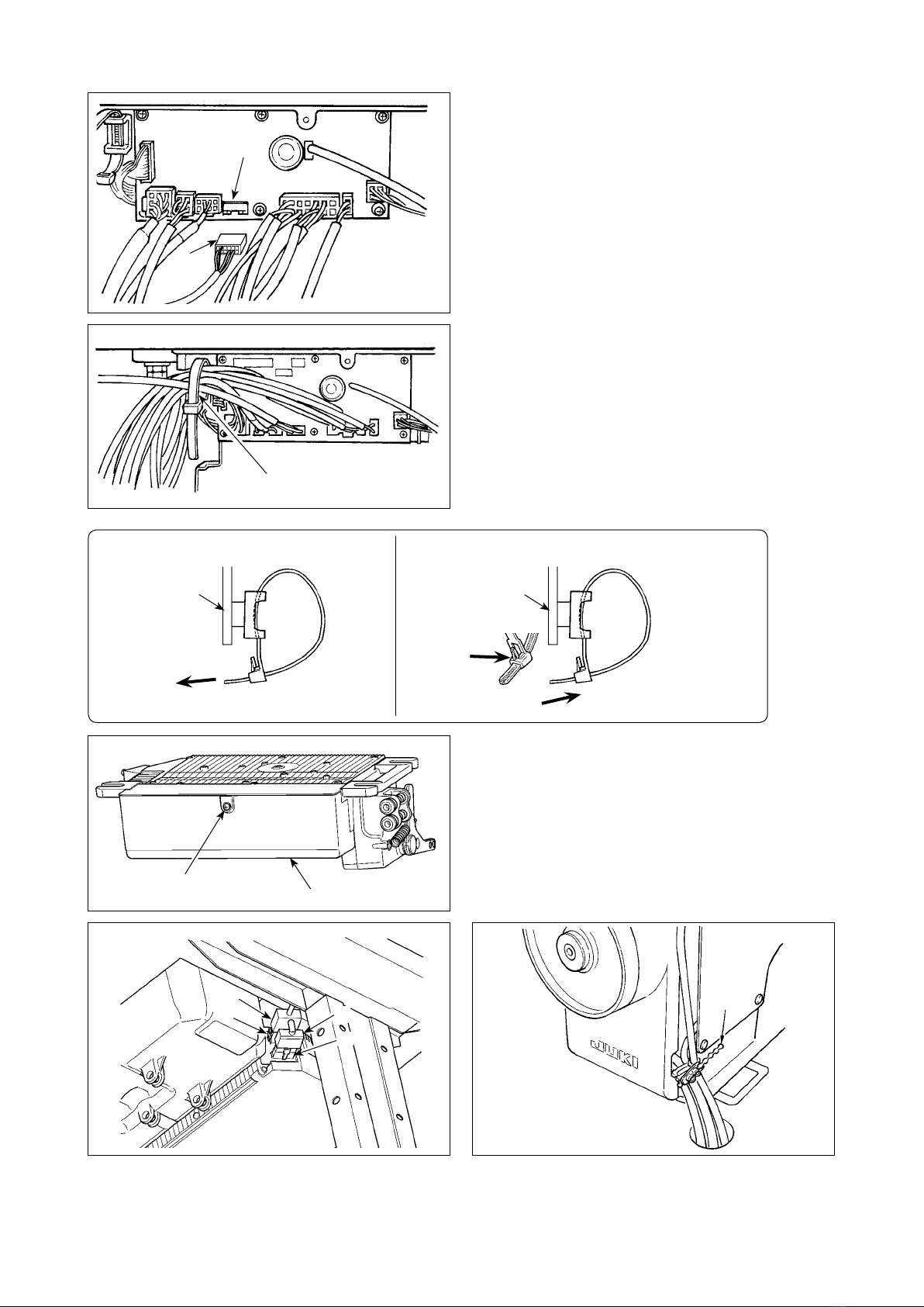
1Replacement of the power cords
2 Changing-round of connector 1 on the PWR PCB
1) Turn OFF the power with the power switch after
checking that the sewing machine has stopped.
2)
Draw out the power cord from the power receptacle
after checking that the power switch has been turned
OFF. Then wait for 5 minutes or more.
3) Loosen the screws which x the cover of the control
box. Open the cover in a slow manner.
4) Changing procedure of the power voltage
(Caution) If the supply power changing is carried out
in a wrong manner, the control box can
break. Be extremely careful when taking the
supply voltage changing procedure.
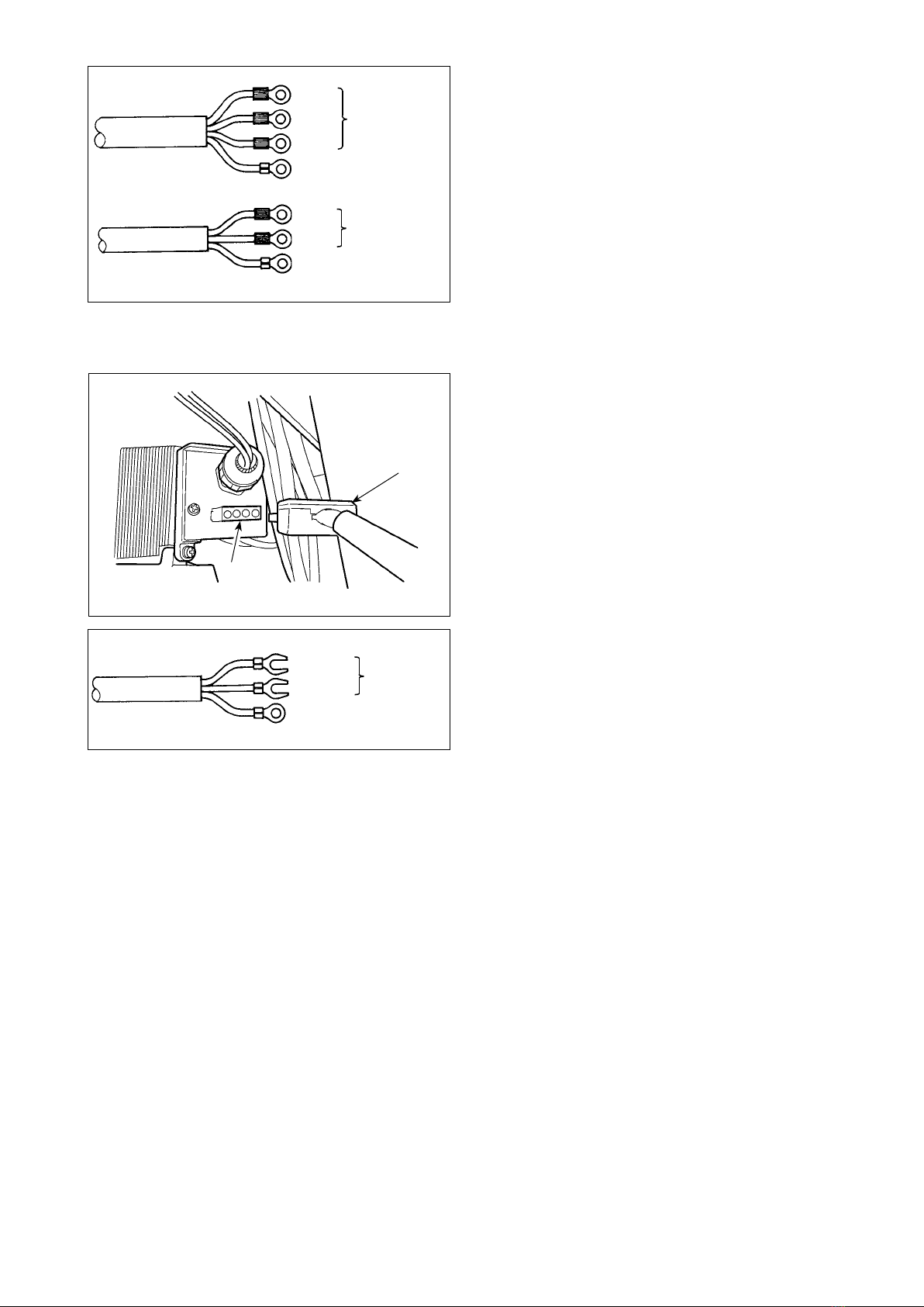
A. To change over the supply voltage from 200 -
240 V to 100 - 120 V
¡Change the power cord with the JUKI genuine
cord with the part number (M90355800A0).
Change the earth cord with the one with the part
number (M90345800A0).
¡Change over supply voltage changeover connec-
tor
1
mounted on the PWR PCB with the con-
nector for 100 V.
¡Connect the crimp style terminal of AC input cord
to the power plug as shown in the gure A.
B,C. To change over the supply voltage from 100 -
120 V to 200 - 240 V
¡Change the power cord with the JUKI genuine
cord with the part number
(M90175800A0).
¡
Change over supply voltage changeover connec-
tor
1
mounted on the PWR PCB with the con-
nector for 200 V.
¡
Connect the crimp contact of the AC input cord
to the power plug as illustrated in Fig. B for the
3-phase power supply or as illustrated in Fig. C
for the single-phase one.
5) Before closing the door, check to be sure again that
the voltage has been changed without mistake.
6) Close the back lid and secure with the screws
pressing the lid, while taking extra care to prevent
the cord from being caught between the cover and
the main body of the control box.
1
2
3
1. Changing over the voltage between 100 V and 200 V
WARNING :
To prevent personal injuries caused by electric shock hazards or abrupt start of the sewing machine,
carry out the work after turning OFF the power switch and a lapse of 5 minutes or more. To prevent
accidents caused by unaccustomed work or electric shock, request the electric expert or engineer of
our dealers when adjusting the electrical components.
1
A
* The illustration below shows the PWR-T PCB.
The type of PCB differs by destination.
(Plug side)
WHITE
BLACK
RED
GREEN/
YELLOW
WHITE
BLACK
GREEN/
YELLOW
Wiring for the single-phase 100 V
Be sure to connect the wire between 1 and 2.
If it is connected between 1-3 or 2-3, the sewing
machine will be inoperative.
(Box side)
1
2
3

– 3 –
1
2. Installing to the table
In the case the SC-920 is used for the DD (direct-drive) type sewing machine head, install the control box on the
table following the instructions give below.
The description given below refers to the case
the SC-920 is installed on the table of the
DDL-9000B. To use any other machine head,
install the control box on the table referring to
the Instruction Manual for the main body of the
relevant sewing machine.
1) Install the control box to the table with the
tting bolt (asm.) 1supplied with the unit
as accessories. At this time, insert the nut
and washer supplied with the unit as ac-
cessories as shown in the gure so that
the control box is securely xed.
2) After having installed the control box (and
the compact motor) on the table, mount
the sewing machine head on the table.
(Refer to the Instruction Manual for the
sewing machine to be used.)
Plain washer Spring
washer Hexagonal
nat
3. Installing the control panel
WARNING :
To protect against possible personal injury due to abrupt start of the machine, be sure to start the
following work after turning the power off and a lapse of 5 minutes or more.
1) Remove side plate setscrews 1from the side
plate.
1
2) Install control panel 2on the machine head using
screws 5, at washers 3and rubber seat 4sup-
plied with the control panel as the accessories.
(Caution) 1. DDL-9000B (Not provided with AK)
is given as an example of installing
procedure.
2. Screw to install the panel changes
according to the machine head
used. Refer to Table 1 (p.4) and
conrmthekindofscrew.
2
4
5
3
Other manuals for SC-920
2
Table of contents
Other JUKI Sewing Machine manuals

JUKI
JUKI LU-1560 User manual

JUKI
JUKI SC-920 User manual

JUKI
JUKI LU-2200 Series User manual

JUKI
JUKI AK118 User manual

JUKI
JUKI DP-2100 User manual

JUKI
JUKI DLD-5430N User manual

JUKI
JUKI LK-1900S Series User manual

JUKI
JUKI M-1 Series User manual

JUKI
JUKI DDL-8300N User manual

JUKI
JUKI AMS-224EN-4530 Manual

JUKI
JUKI MO-2000QVP User manual

JUKI
JUKI TL-2200QVP Mini User manual

JUKI
JUKI IP-310/ACF-172-1790 User manual

JUKI
JUKI DX-4000QVP User manual

JUKI
JUKI DDL-9000B User manual

JUKI
JUKI DDL-8700L User manual

JUKI
JUKI DDL-9000B-SH Installation and operation manual

JUKI
JUKI MO-6704D User manual

JUKI
JUKI MH-486-5 User manual

JUKI
JUKI MO-6900C Series User manual