Jung BTS01 Operator's manual

Art. No. BTS01
Table of Contents
Product definition1 3.................................................................................................................
Product catalogue1.1 3...........................................................................................................
Function1.2 3..........................................................................................................................
Mounting, electrical connection and operation2 4.................................................................
Safety instructions2.1 4...........................................................................................................
Device components2.2 5........................................................................................................
Parts2.2.1 5........................................................................................................................
Dimensions (mm)2.2.2 6....................................................................................................
Fitting and electrical connection2.3 7......................................................................................
Commissioning and function2.4 9...........................................................................................
Obvious misuse2.5 10............................................................................................................
Technical data3 11....................................................................................................................
Application examples4 12........................................................................................................
Example "valve drive (motor-operated) with controller"4.1 12................................................
Example: "KNX pushbutton interface"4.2 14..........................................................................
Appendix5 16.............................................................................................................................
Index5.1 16.............................................................................................................................
Product documentation
Page 2 of 17

Art. No. BTS01
1 Product definition
1.1 Product catalogue
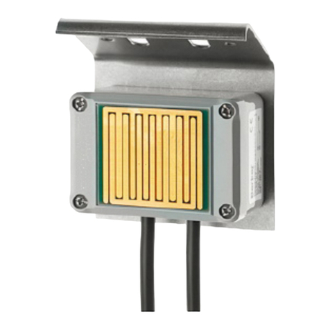
Product name: Condensation sensor
Use: Sensor
Design: SM
Art. No. BTS01
1.2 Function
General
The device serves to detect unwanted condensation, in particular on coolant lines in residential
or functional buildings. For example, condensed water can run down coolant lines or drip from
cooling ceilings to the false ceiling and cause damage to it. If condensation is detected early,
damage can be kept minor.
The device is fitted to the pipe that is to be monitored and, in combination with an appropriate
KNX evaluation unit, it is a convenient and smart solution to detect condensation. The
evaluation unit evaluates the signals of the device and transmits the appropriate telegrams to
the KNX. KNX pushbutton interfaces or similar binary inputs can be suitable evaluation units.
iThe device is a conventional sensor that is operated on an evaluation unit (e.g. KNX valve
drive (motor-operated) with controller).
Application examples
In cooling ceilings:
- On coolant lines
Page 3 of 17
Product definition

Art. No. BTS01
2 Mounting, electrical connection and operation
2.1 Safety instructions
Electrical devices may only be mounted and connected by electrically skilled
persons.
Failure to observe the instructions may cause damage to the device and result in fire and
other hazards.
Danger of electric shock. During installation and cable routing, comply with the
regulations and standards which apply for SELV circuits.
Page 4 of 17
Mounting, electrical connection and operation

Art. No. BTS01
2.2 Device components
The device consists of a unit, including connection cable. The device may not be opened.
i The device will be destroyed if it is opened.
2.2.1 Parts
Figure 1: Device components Condensation sensor
(1) Connecting cable
(2) Fixing strap
(3) Recession for fitting on ductwork with cable ties
(4) Recession for a thermally conducting pad
(5) Sensor surface
Page 5 of 17
Mounting, electrical connection and operation

Art. No. BTS01
2.2.2 Dimensions (mm)
Figure 2: Top view
Figure 3: Bottom view
Figure 4: Page view
Figure 5: Front view
Page 6 of 17
Mounting, electrical connection and operation

Art. No. BTS01
2.3 Fitting and electrical connection
Fitting the condensation sensor
The installation location should be the position that is most likely to have condensation. That
can be the coldest spot within a pipeline circuit.
iFor proper function, the sensor surface must be ventilated so that condensation can form
on it.
iWhen fitted in the vicinity of mixer valves, place the device on the colder inflow.
Precondition: an appropriate fitting site
oClean the outer surface of the pipe.
Remove any existing remaining paint.
oRemove the protective film from the enclosed thermally conducting pad.
oPut the self-sticking thermally conducting pad in the recession for the thermally conducting
pad and slightly press on.
Result: The thermally conducting pad adheres to the recession on the bottom side of the
device.
oPlace the bottom side of the device directly on the pipe that is to be monitored.
oFit the device to the pipe with the accompanying cable ties.
oFit the connecting cable, e.g. with nail clamps.
Figure 6: Fitting the device
(6) Pipe
(7) Cable tie
(8) Thermally conducting pad
Page 7 of 17
Mounting, electrical connection and operation

Art. No. BTS01
Connecting the condensation sensor
The device is directly connected to an evaluation unit (e.g. KNX valve drive (motor-operated)
with controller) and electrically supplied by it.
Figure 7: Connecting the device
(9) Evaluation unit
oConnect the device to an evaluation unit that supplies and monitors the device.
iObserve the polarity:
Brown = +
Blue = - / GND
iReverse polarity protection protects the device from incorrect connection (Polarity from +
and - / GND). The device does not function but is not destroyed.
iThe device will be destroyed if it is connected to a voltage source that allows for a high
current (voltage)!
Page 8 of 17
Mounting, electrical connection and operation

Art. No. BTS01
2.4 Commissioning and function
Commissioning of the dew sensor
The following specification must be set in the parameters of the evaluation unit (e.g. KNX valve
drive (motor-operated) with controller):
- Debounce time: 127 ms
Function of the dew sensor
The device monitors the electrical conductivity between the conductive coatings on the sensor
surface. If it is dampened with water, the device detects the change and signals it.
The device is electrically supplied by an evaluation unit. The signaling of an alarm takes place
by short-circuiting the supply voltage. The device supplies itself internally while it is short
circuited.
When the sensor surface is moistened, the device signals an alarm (rising edge) of the
evaluation unit. An internal clock measures the time beginning at this moment. The device of the
evaluation unit signals an alarm for the duration of 1 minute. The device signals an alarm as
long as the sensor surface is moistened. Even if the sensor surface is free from liquid within the
first minute, the device still signals an alarm for one minute. After the minute is up, the device
checks to see if the sensor surface is still moistened. As soon as the sensor surface is no longer
moistened, the device cancels the alarm signal (falling edge).
The signal is recorded by the KNX device used by the evaluation unit and transmitted to the
KNX in accordance with the project design. As a rule, the polarity of the KNX telegrams can be
set in the parameters of the KNX device. In accordance with the project design, "1" telegrams or
"0" telegrams are transmitted on the KNX if there is a rising or falling edge.
The device does not function in the event of prolonged supply voltage failure. The device
automatically resumes functioning upon the return of the supply voltage.
iThe device cannot prevent the accumulation of condensation, but still detects and registers
it early, so that the impact of the unwanted condensation can be kept minor.
iThe sensor surface can be damaged if it comes into contact with aggressive media (e.g.,
detergent solutions, scrubbing brines or acidic condensation from condensing boilers). The
sensor area is to be checked after every alarm. The device is to be exchanged in the event
of significant damage from corrosion.
Page 9 of 17
Mounting, electrical connection and operation
Art. No. BTS01
2.5 Obvious misuse
The device works with the upper surface of the sensor. The lower surface of the sensor is not
active. The device is not suitable for use as a leakage sensor.
Figure 8: Example of obvious misuse of the device
Page 10 of 17
Mounting, electrical connection and operation
Art. No. BTS01
3 Technical data
Rated voltage DC 3,3 ... 5VSELV
Current consumption typ. 0,5mA
Short-circuit current max. 100mA
Protection class III
Ambient temperature 0 ... +50°C
Storage/transport temperature -40 ... +100°C
Connecting cable 2m
Degree of protection IP 67
Page 11 of 17
Technical data

Art. No. BTS01
4 Application examples
4.1 Example "valve drive (motor-operated) with controller"
Example: direct operation on KNX valve drive (motor-operated) with controller (Art. no.:
2177SVR)
This application example shows the direct operation of the condensation sensor on KNX valve
drive (motor-operated) with controller.
Figure 9: Connecting the condensation sensor to KNX valve drive (motor-operated) with
controller
(1) Connecting cable to the condensation sensor
(9) Evaluation unit (here: KNX valve drive (motor-operated) with controller)
(10) Dew sensor
(11) Device connection terminal for potential-free contact or remote sensor
(12) Connecting cable KNX
Page 12 of 17
Example "valve drive (motor-operated) with controller"

Art. No. BTS01
The KNX valve drive (motor-operated) with controller is planned with the ETS and brought into
operation. So that the condensation sensor can be operated on the KNX valve drive (motor-
operated) with controller, the following settings are to be changed in the parameters of the KNX
valve drive (motor-operated) with controller, on the "entry" side of the parameters:
- "Function of the input" = "Switching"
With the "Switching" function, the ETS displays two 1-bit communication objects (switching
1.1 and 1.2). It is possible to use these two objects to transmit different switching telegrams
to the KNX depending on the signal edge at the input. The input parameter on the
parameter page "Input" can be used to define which object value is transmitted to the KNX
when there is a rising or falling edge at the input (no reaction, ON, OFF, TOGGLE -
switchover of the object value).
- "Delay after reset or when bus voltage returns" = 5 seconds
This parameter defines the delay after a reset or bus voltage return. Within the first few
seconds (approx. 4 seconds), the leakage sensor signals an alarm after it is supplied with
voltage. The alarm is triggered and then cancelled during the start-up phase of the device.
For each evaluation unit implemented, a lag time can be set depending on bus voltage
discovery, through which the transmission of the first KNX telegrams can be suppressed
due to the startup phase of the leakage sensor.
- "Debounce time": 127 ms
The debounce time of the signal is defined by the device software via the parameter
"Debounce time". The debounce time is defined for the functions of the binary input, after
which actuation period the binary inputs identify a valid actuation of the connected
contacts. In this way, it is possible to prevent the device from mistakenly identifying short
conduction faults as a signal. The debounce time makes it possible to adapt the signal
evaluation to the contact quality of the connected switches or push-buttons as well. The
debounce time must be increased in the ETS if undesirable signal evaluations with very
fast edge changes occur regularly or sporadically resulting in rapidly changing states of the
KNX telegrams.
- "Command on rising edge" = ON
This parameter can be used to define which object value is transmitted first to the KNX via
the first communication object of the input when there is a rising edge.
- "Command on falling edge" = OFF
This parameter can be used to define which object value is transmitted first to the KNX via
the first communication object of the input when there is a falling edge.
Page 13 of 17
Example "valve drive (motor-operated) with controller"

Art. No. BTS01
4.2 Example: "KNX pushbutton interface"
Example: direct operation on jung knx pushbutton interface 2-gang (Art. no.: 2076-2 T)
This application example shows the direct operation of the condensation sensor on a KNX
pushbutton interface without additional voltage supply.
Figure 10: Connecting the condensation sensor to the KNX pushbutton interface
(1) Connecting cable to the condensation sensor
(9) Evaluation unit (here: KNX pushbutton interface)
(10) Dew sensor
(13) Two-conductor terminals
(14) Connecting cable reference potential (com) of the KNX pushbutton interface
(15) Channel 1 connecting cable of the KNX pushbutton interface
(16) Device connection terminal KNX
iMaximum one sensor may be connected to a channel of an jung KNX pushbutton interface.
With simultaneous signaling of alarms on both channels, the second message will sent
delayed on the KNX.
The KNX pushbutton interface is planned with the ETS and brought into operation. So that the
condensation sensor can be operated on the KNX pushbutton interface, in the parameters of
the KNX pushbutton interface, the following settings are to be changed:
- "Function of Channel x" = binary input
This parameter defines the functions of the channel.
Page 14 of 17
Example: "KNX pushbutton interface"

Art. No. BTS01
- "Delay after bus voltage returns" = 5 seconds
After reset or bus voltage return, the application program of the KNX pushbutton interface
can be disabled for a defined time period until the corresponding reactions are executed.
No pending signals will be evaluated on the inputs during this time and the switch outputs
are not controlled! Even a feedback will only be transmitted after the time delay has
elapsed at the earliest. Within the first few seconds (approx. 4 seconds), the leakage
sensor signals an alarm after it is supplied with voltage. The alarm is triggered and then
cancelled during the start-up phase of the device. For each evaluation unit implemented, a
lag time can be set depending on bus voltage discovery, through which the transmission of
the first KNX telegrams can be suppressed due to the startup phase of the leakage sensor.
- "Debounce time for binary inputs" = 127 ms
Specifies the software debounce time for all binary inputs together. On the basis of the time
set here, a signal edge is evaluated at the input with a delay.
- "Function of the input" = "Switching"
With the "Switching" function, the ETS displays two 1-bit communication objects (switching
object 1.1 and 1.2). It is possible to use these two objects to transmit different switching
telegrams to the KNX depending on the signal edge at the input. The input parameter on
the parameter page "Input" can be used to define which object value is transmitted to the
KNX when there is a rising or falling edge at the input (no reaction, ON, OFF, TOGGLE -
switchover of the object value).
- "Command on rising edge" = ON
This parameter can be used to define which object value is transmitted first to the KNX via
the first communication object of the input when there is a rising edge.
- "Command on falling edge" = OFF
This parameter can be used to define which object value is transmitted first to the KNX via
the first communication object of the input when there is a falling edge.
Page 15 of 17
Example: "KNX pushbutton interface"

5 Appendix
5.1 Index
A
Application examples................................3
B
Bottom view.............................................. 6
C
Corrosion damages.................................. 9
D
Debounce time..........................................9
F
Front view................................................. 6
P
Page view................................................. 6
R
Reverse polarity protection.......................8
T
Top view................................................... 6
Art. No. BTS01 Page 16 of 17
Appendix

Art. No. BTS01
ALBRECHT JUNG GMBH & CO. KG
Volmestraße 1
58579 Schalksmühle
GERMANY
Telefon: +49 2355 806-0
Telefax: +49 2355 806-204
www.jung.de
Page 17 of 17
Appendix
Other manuals for BTS01
1
Table of contents
Other Jung Accessories manuals

Jung
Jung 2074 TSM User manual

Jung
Jung SCHUKO 1520-15 Series User manual

Jung
Jung UMA-CAT6A User manual

Jung
Jung RW 95 User manual

Jung
Jung SCHUKO BT 1521S Series User manual

Jung
Jung LES01 User manual

Jung
Jung BTS01 User manual

Jung
Jung KNX WS 10 D User manual

Jung
Jung 65 WIS User manual

Jung
Jung TK AS AL 114 User manual