Jung 2072 TSM User manual

KNX/EIB
Product documentation Page: 1 of 29
Hardware description
2-gang
standard push button sensor 'TSM' Sensor
Product name 2-gang standard push button sensor 'TSM'
Design: flush-mounted (UP)
Article no. 2072 TSM
ETS search path Push button / Push button 2-gang / 2-gang standard push button sensor 'TSM'
Issue: 21.09.2005
Functional description:
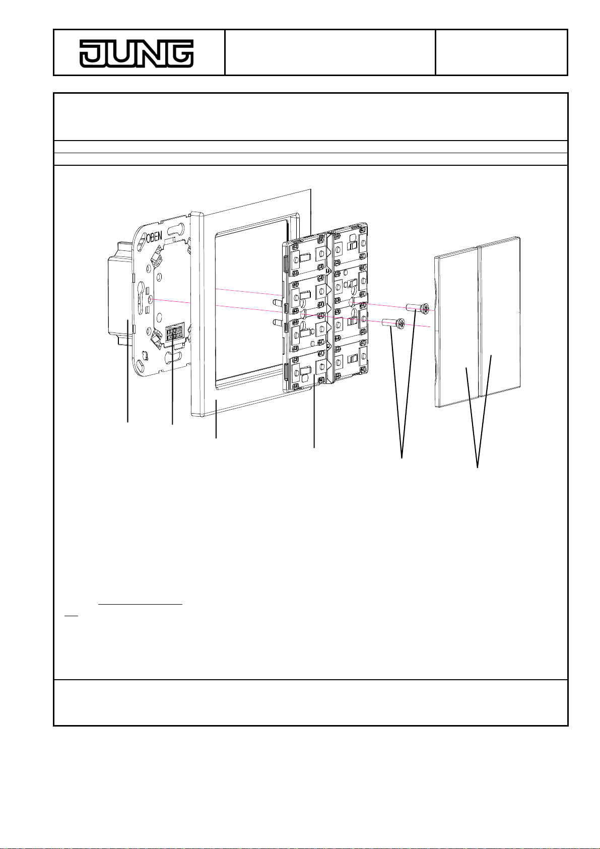
The 2-gang standard push button sensor 'TSM' is plugged onto a flush-mounted bus coupling unit (BCU) (cf.
connection diagram). After a press on the key, the push button sensor will transmit software-dependent telegrams
to the KNX / EIB. These may be telegrams for switching, pushbutton operation, dimming or for shutter control. It is
also possible to program value-transmitting functions such as dimming value transmitter or light-scene extension
units. A blue operation LED can serve as orientation lighting
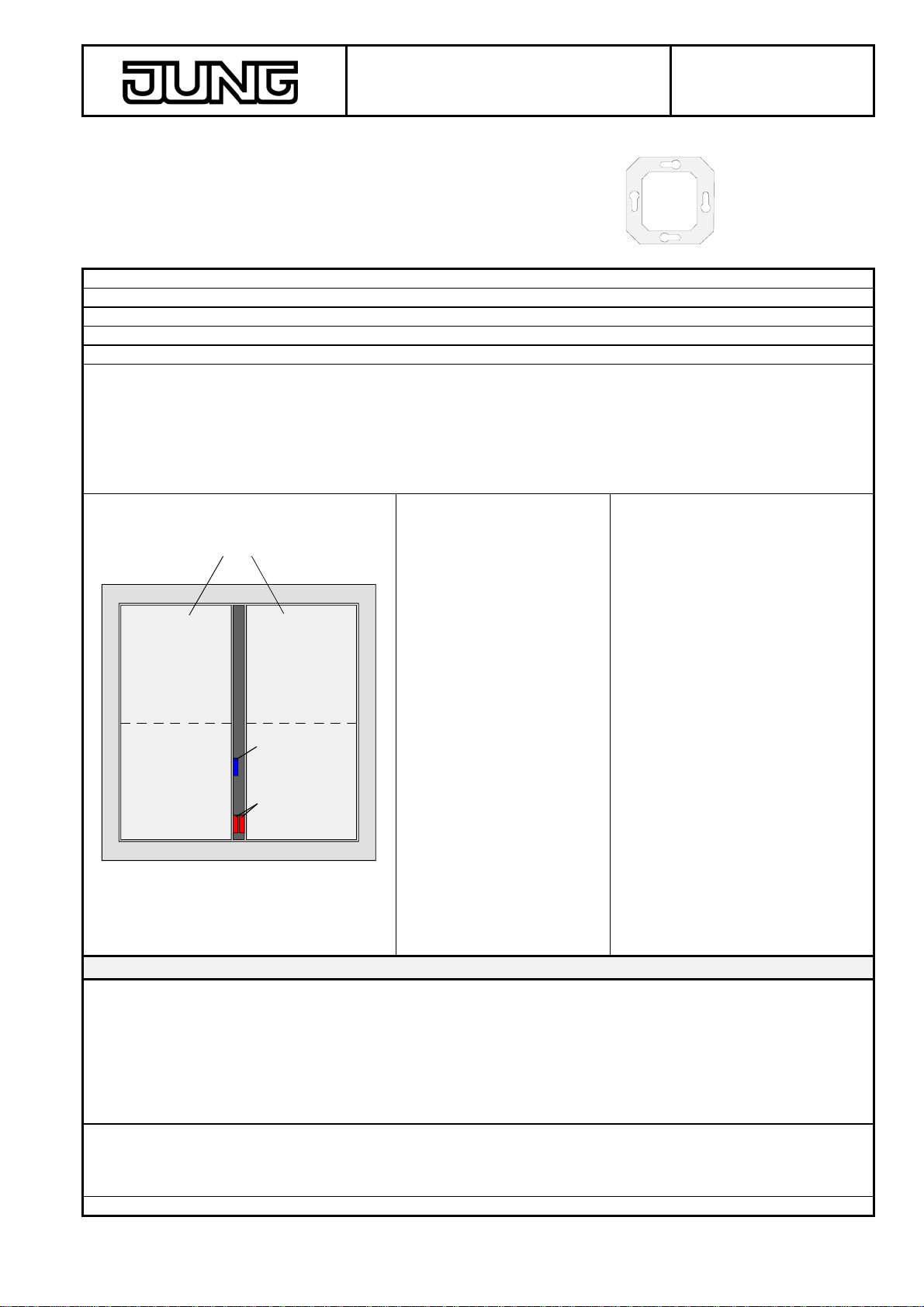
Layout: Dimensions: Controls:
A
B
C
13
24
Width: 70 mm (without
frame)
Height: 70 mm (without
frame)
Depth: 7 mm (without PEI)
A: 2 rockers (keys 1 to 4: key-press
on upper and lower half of
respective rocker)
The device is operated with the
corresponding push button
sensor module covers. The
covers must be ordered
separately:
2 x FD..902 TSA..
Covers with article nos.
FD..90x TSA NA.. can be
labelled. For labelling,
commercial-grade foils can be
printed with the JUNG inscription
software and inserted into the
keys.
B: 2 status LEDs (red), one per
rocker
C: 1 operation LED (blue)
Technical Data
Type of protection: IP 20
Safety class: III
Mark of approval: KNX / EIB
Ambient temperature: -5 °C ... +45 °C
Storage / transport temperature: -25 °C ... +70 °C (storage above +45 °C reduces the lifetime)
Mounting position: any
Minimum distances: none
Type of fastening: plugging onto flush-mounted (BCU 1)
KNX / EIB supply
Voltage: 21 – 32 V DC (SELV) via flush-mounted BCU
Power consumption: typically 150 mW
Connection: 2 x 5-pole pin contact strip
External supply ---

KNX/EIB
Product documentation Page: 2 of 29
Hardware description
Response to bus voltage failure
Bus voltage only: object values are deleted, LEDs extinguished
Response on return of bus voltage
Bus voltage only: no reaction
Input: ---
Output: ---
Connection and terminals:
(A) (C) (D) (E) (F)
(B)
Fitting:
- Connect the KNX/EIB bus coupling unit (A) to the KNX/EIB and install in a flush-mounting box. If possible,
program the bus coupler beforehand with the physical address.
- Plug the 2-gang standard push button sensor 'TSM' (D) together with decorative frame (C) on the KNX/EIB bus
coupling unit in such a way that both devices are interconnected via user interface (B).
- Fasten the 2-gang standard push button sensor 'TSM' with the plastic screws (E) supplied with the device to the
KNX/EIB bus coupling unit. The screws serve as a protection against removal or theft. Tighten the plastic
screws without using force. Important: Use only the plastic screws supplied with the device. Metal screws are
not admissible. Risk of irreparable damage to the device caused by electrostatic discharge.
- Install the push button sensor module covers (F: key rockers). The covers must be ordered separately: The
covers must be snapped one after another onto the 2-gang standard push button sensor 'TSM'. Make sure the
covers are fitted in correct position (marking TOP on the inside). The covers are installed permanently by
snapping them onto the device.
Hardware remarks
---

KNX/EIB
Product documentation Page: 3 of 29
Hardware description
Software description
ETS search path
Push button / Push button 2-gang / 2-gang standard push button sensor 'TSM'
ETS symbol:
2
PEI type 04 Hex 4
Dec 2 inputs / 2 outputs
Applications:
No. Summarized description: Name: Version:
1 Switching, status Switching, status 100312 1.2
2 Switching, acknowledgement Switching, acknowledgement 100A12 1.2
3 Dimming Dimming 102A01 0.1
4 Shutter Shutter 102B01 0.1
5 Shutter with status object Shutter with status object 108C01 0.1
6 Dimming / shutter Dimming / shutter 103A01 0.1
7 Switching / dimming Switching / dimming 103C01 0.1
8 Switching / shutter Switching /shutter 103B01 0.1
9 Switching / pushbutton operation Switching / pushbutton operation 103101 0.1
10 Value transmitter Value transmitter 101C01 0.1

KNX/EIB
Product documentation Page: 4 of 29
Hardware description
Application: 1. Switching, status 100312
Executable from mask version: 1.0
Number of addresses (max): 10 dynamic table handling Yes :No
Number of assignments (max): 10 maximum length of table 20
Communication objects 2
Object Function Name: Type Flag
0 Switching Rocker 1 1 bit C, W, T
1 Switching Rocker 2 1 bit C, W, T
Object description
Objects:
0 - 1 Switching 1-bit object for the transmission of switching telegrams (ON, OFF)
Scope of functions
•Function of operating LED and of status LED parameterizable
•Command on key press parameterizable (ON, OFF)

KNX/EIB
Product documentation Page: 5 of 29
Hardware description
Parameters
Description: Values: Remarks:
General
Operation LED
OFF
ON
Defines the status of the operation LED.
Command on pressing of
key 1/3 OFF
ON
Defines the command transmitted on pressing
of key 1/3.
Command on pressing of
key 2/4
OFF
ON Defines the command transmitted on pressing
of key 2/4.
Rocker 1
Function status LED
OFF
ON
Determines the status of the operation LED.
Rocker 2
Function status LED
OFF
ON
Defines the status of the operation LED.
Software remarks
•The status LEDs indicate the current state of the object. If a key is pressed (e.g. ON) and if the push button
sensor does not get a positive acknowledgement (IACK) from an addressed actuator, the object status is
updated, but the corresponding status LED is not lit up.

KNX/EIB
Product documentation Page: 6 of 29
Hardware description
Application: 2. Switching, acknowledgement 100A12
Executable from mask version: 1.0
Number of addresses (max): 8 dynamic table handling: Yes :No
Number of assignments (max): 9 maximum length of table: 17
Communication objects 2
Object Function Name Type Flag
0 Switching Rocker 1 1 bit C, W, T
1 Switching Rocker 2 1 bit C, W, T
Object description
Objects:
0 - 1 Switching: 1-bit object for the transmission of switching telegrams (ON, OFF)
Scope of functions
•Function of operating LED and of status LED parameterizable
•Command on key-press parameterizable (ON, OFF)

KNX/EIB
Product documentation Page: 7 of 29
Hardware description
Parameters
Description: Values: Remarks:
General
Operation LED
OFF
ON
Defines the status of the operation LED.
LED ON-time rocker 1 and 2 0.75 s
1.5 s
2.25 s
2.7 s
3.0 s
4.5 s
6.0 s
10 s
15 s
20 s
Defines the time during which the status LEDs
of rockers 1 and 2 are on in case of a positive
acknowledgement from an addressed actuator.
Command on pressing of
keys 1/3 OFF
ON
Defines the command transmitted on pressing
of key 1/3.
Command on pressing of
keys 2/4
OFF
ON Defines the command transmitted on pressing
of key 2/4.
Rocker 1
Function status LED
OFF
ON
Defines the status of the status LED.
Rocker 2
Function status LED
OFF
ON
Defines the status of the status LED.
Software remarks
•The status LED is on for a parameterizable time in case of a positive acknowledgement from an addressed
actuator. If a key is pressed (e.g. ON) and if the push button sensor does not get a positive acknowledgement
(IACK) from an addressed actuator, the object status is updated, but the corresponding status LED is not lit up.

KNX/EIB
Product documentation Page: 8 of 29
Hardware description
Application: 3. Dimming 102A01
Executable from mask version: 1.0
Number of addresses (max): 6 dynamic table handling: Yes :No
Number of assignments (max): 6 maximum length of table: 12
Communication objects 4
Object Function Name Type Flag
0 Switching Rocker 1 1 bit C, W, T
1 Switching Rocker 2 1 bit C, W, T
2 Dimming Rocker 1 4 bit C, T
3 Dimming Rocker 2 4 bit C, T
Object description
Objects:
0 - 1 Switching: 1-bit object for the transmission of switching telegrams (ON, OFF)
2 - 3 Dimming: 4-bit object for change of relative brightness between 0 and 100 %
Scope of functions
•Function of operating LED and of status LED parameterizable

KNX/EIB
Product documentation Page: 9 of 29
Hardware description
Parameters
Description: Values: Remarks:
General
Operation LED
OFF
ON
Defines the status of the operation LED.
Function status LED OFF
ON
Defines the status of the status LED.
Software remarks
•The status LED indicates the current status of the switching object. If a key is pressed (e.g. ON) and if the push
button sensor does not get a positive acknowledgement (IACK) from an addressed actuator, the object status is
updated and the corresponding status LED is lit up.

KNX/EIB
Product documentation Page: 10 of 29
Hardware description
Application: 4. Shutter 102B01
Executable from mask version: 1.0
Number of addresses (max): 8 dynamic table handling: Yes :No
Number of assignments (max): 8 maximum length of table: 16
Communication objects 4
Object Function Name Type Flag
0 Short-time operation Rocker 1 1 bit C, W, T
1 Short-time operation Rocker 2 1 bit C, W, T
2 Long-time operation Rocker 1 1 bit C, W, T
3 Long-time operation Rocker 2 1 bit C, W, T
Object description
Objects:
0 – 1 Short-time operation 1-bit object for short-time operation of a shutter
2 - 3 Long-time operation 1-bit object for long-time operation of a shutter
Scope of functions
•Function of operation LED parameterizable
Parameters
Description: Values: Remarks:
General
Operation LED
OFF
ON
Defines the status of the operation LED.

KNX/EIB
Product documentation Page: 11 of 29
Hardware description
Application: 5. Shutter with status object 108C01
Executable from mask version: 1.2
Number of addresses (max): 8 dynamic table handling: Yes :No
Number of assignments (max): 9 maximum length of table: 17
Communication objects: 7
Object Function Name Type Flag
0 Short-time operation Rocker 1 1 bit C, T
1 Short-time operation Rocker 2 1 bit C, T
2 Long-time operation Rocker 1 1 bit C, T
3 Long-time operation Rocker 2 1 bit C, T
Object for status function (only when status LED = status indicator):
4 Status Status LED 1 1 bit C, W
5 Status Status LED 2 1 bit C, W
Object for operation LED (only when operation LED = status indicator):
6 Status Operation LED 1 bit C, W
Object description
Objects:
0 - 1 Short-time operation 1-bit object for short-time operation of a shutter
2 - 3 Long-time operation 1-bit object for long-time operation of a shutter
4 - 5 Status 1-bit object for status LED control
6 Status 1-bit object for operation LED control
Scope of functions
•Both, the operation and also the status LED can be controlled by separate objects (status indication) or be
permanently on or off. The status LEDs can additionally act as key-press indicators.
•Operating concept for shutter control parameterizable
•Time between short-time and long-time operation and slat adjustment time (time during which a long-time
command (Move) can be terminated by releasing the key at the input) presettable depending on operating
concept.
•Rocker configuration and key functions presettable.

KNX/EIB
Product documentation Page: 12 of 29
Hardware description
Parameters
Description: Values: Remarks:
General
Operation LED function
LED always ON
LED always OFF
Status indication
Inverted status indication
Defines the functioning of the operation LED.
In the status indication (also inverted status
indication) setting, the LED is controlled via
object 6.
Operating concept Step – Move – Step
Move – Step
Step – Move
Move – Step or Step
Defines the operating concept (cf. software
remarks).
Time between short- and
long-time operation,
base
0.5 ms
8 ms
130 ms
2.1 s
33s
Defines the time base up to long-time operation.
Time = base •factor
Depending on parameter "Operating concept"
Time between short- and
long-time operation,
factor (2...255)
3 ... 255, 30 Defines the time factor up to long-time
operation.
Presetting: 8 ms •30 = 240 ms
Depending on parameter "Operating concept"
Slat adjustment time,
base 0 ms
0.5 ms
8 ms
130 ms
2.1 s
33s
Time during which a long-time operation for slat
adjustment can be terminated by releasing the
key.
Time = base •factor
Depending on parameter "Operating concept"
Slat adjustment time,
factor (1...255)
3 ... 255; 250 Time during which a long-time operation for slat
adjustment can be terminated by releasing the
key.
Presetting: 8 ms •255 = 2.0 s
Depending on parameter "Operating concept"

KNX/EIB
Product documentation Page: 13 of 29
Hardware description
Rocker 1
Function status LED
LED always ON
LED always OFF
Status indication
Inverted status indication
Key-press indication
Defines the functioning of the status LED.
In the status indication (also inverted status
indication) setting, the LED is controlled via
object 4.
In the "Key-press indication" setting, the LED
lights up during the time of a press on any of the
keys of the push button sensor.
Rocker configuration Key 1 and 2
Key 1 and 3 Defines the rocker configuration and thus the
evaluation of the keys.
The rocker 1 function is assigned to the two
keys 1 and 2 on the left. The function is
activated in this case by a press on the upper
and lower part of the the lefthand rocker.
The rocker 1 function is assigned to the two
keys at the top. The function is activated in this
case by a press on the upper left and the upper
right key.
The rocker 2 function is then always activated
by the two keys remaining free after assignment
of the rocker 1 function.
Key function Key 1 UP, key 2 DOWN
Key 1 DOWN, key 2 UP
or
Key 1 UP, key 3 DOWN
Key 1 DOWN, key 3 UP
* Depending on parameter
"Rocker configuration"
This parameter defines the key command (UP
or DOWN) for the two keys assigned depending
on the parameter "Rocker function".

KNX/EIB
Product documentation Page: 14 of 29
Hardware description
Software remarks
Operating concept Step–Move-Step:
A press on the key triggers a Step telegram. The time T1 between short-time and long-time operation is started.
Releasing the key before time T1 has elapsed does not trigger another telegram. If the key is still pressed when
the time elapses, a Move telegram is transmitted. Slat adjustment time T2 is started. If the key is released while
slat adjustment is still in progress, the push button sensor transmits a Step telegram. If time T2 has elapsed when
the key is being released, no further telegram will be transmitted.
T1 T2
Releasing = STEP no action
STEP MOVE
key pressed
Operating concept Move-Step:
A press on the key triggers a Move telegram. Slat adjustment time T2 is started. Releasing the key before the slat
adjustment time has elapsed causes a Step telegram to be transmitted. If time T2 has elapsed when the key is
being released, no further telegram will be transmitted.
T2
Releasing = STEP no action
MOVE
key pressed
Operating concept Step–Move:
A press on the key triggers a Step telegram. The time T1 between short- and long-time operation is started.
Releasing the key before time T1 has elapsed does not trigger another telegram. If the key is still pressed when
the time elapses, a Move telegram is transmitted. Releasing the key after this point of time will not trigger any
further actions.
T1
Releasing = no action no action
STEP
key pressed
MOVE

KNX/EIB
Product documentation Page: 15 of 29
Hardware description
Operating concept Step-Move or Step
A press on the key starts time T1 between short- and long-time operation. At this time, no telegram will be
transmitted. Releasing the key before time T1 has elapsed will cause a Step telegram to be transmitted. Only if
the key is kept pressed after time T1 has elapsed, will the push button sensor trigger a Move telegram. Slat
adjustment time T2 is started. If the key is released while slat adjustment is still in progress, the push button
sensor transmits a Step telegram. If the time has elapsed when the key is being released, no further telegram will
be transmitted.
T1 T2
Releasing = STEP no action
MOVE
key pressed
Releasing = STEP

KNX/EIB
Product documentation Page: 16 of 29
Hardware description
Application: 6. Dimming / shutter 103A01
Executable from mask version: 1.1
Number of addresses (max): 6 dynamic table handling: Yes :No
Number of assignments (max): 4 maximum length of table: 10
Communication objects: 4
Object Function Name Type Flag
0 Switching Rocker 1 bit C, W, T
1 Dimming Rocker 4 bit C, T
2 Short-time operation Rocker 1 bit C, W, T
3 Long-time operation Rocker 1 bit C, W, T
Object description
Objects:
0 Switching: 1-bit object for the transmission of switching telegrams (ON, OFF)
1 Dimming: 4-bit object for change of relative brightness between 0 and 100 %
2 Short-time operation 1-bit object for short-time operation of a shutter
3 Long-time operation 1-bit object for long-time operation of a shutter
Scope of functions
•Function of operation LED and ON-time of status LED in case of key-press indication and "Dimming" function
parameterizableStatus indication with "Dimming" function possible
•Rocker 1 as a function of rocker 2 (or vice versa) parameterizable as dimming or shutter sensor
•Key functions (ON/brighter OFF/darker or UP / DOWN) can be parameterized
•Time between switching and dimming, dimming step and transmission of stop telegrams possible with
dimming sensor
•Time between two telegrams and number of steps before continuous run (slat adjustment) presettable in
shutter operation

KNX/EIB
Product documentation Page: 17 of 29
Hardware description
Parameters
Description: Values: Remarks:
General
Operation LED
OFF
ON
Defines the status of the operation LED.
Rocker configuration Rocker 1: dimming
Rocker 2: shutter
Rocker 1: shutter
Rocker 2: dimming
Defines the function of the individual rockers.
Function Dimming
Function of status LED
as status indicator
as key-press indicator
always OFF
always ON
Defines the operation of the status LED.
The status LED indicates the status of the
switching object.
The status LED light up when a key is pressed.
The status LED is always off.
The status LED is always on
LED ON-time 0.75 s; 2.25 s; 3 s, 4.5 s; 6 s;
10 s; 15 s Defines the time during which the status LED is
on when a key is pressed.
Only if "Status LED function = key-press
indicator").
Key function. 1/3 = brighter (ON)
2/4 = darker (OFF)
1/3 = darker (OFF)
2/4 = brighter (ON)
Defines the command transmitted on pressing
of the keys.
Time between switching
and dimming, base
130 ms; 260 ms; 520 ms;
1 s; 2.1 s; 4.2 s; 8,4 s; 17 s; 34 s
1.1 min; 2.2 min; 4.5 min; 9 min;
18 min; 35 min;
1.2 h
Defines the time base for a key-press to send a
telegram
Time = base •factor
Time between switching
and dimming, factor
(2...127)
2 ... 127; 3 Defines the time factor for a key-press to send a
dimming telegram
Time = base •factor
Presetting: 130 ms •3 = 390 ms
Increase brightness by 100 %
50 %
26 %
12.5 %
6 %
3 %
1.5 %
Defines the maximum dimming step performed
on reception of a relative dimming telegram
(brighter).
Reduce brightness by 100 %
50 %
26 %
12.5 %
6 %
3 %
1.5 %
Defines the maximum dimming step performed
on reception of a relative dimming telegram
(darker).

KNX/EIB
Product documentation Page: 18 of 29
Hardware description
Send stop telegram ?
YES
NO
Defines whether a dimming procedure in
progress is to stop when the key is released
(YES).
Function: Shutter
Key function
1/3 = UP, 2/4 = DOWN
1/3 = DOWN, 2/4 = UP
Defines the command transmitted on pressing
the keys.
Number of steps before
continuous run (1...30)
1 ... 30; 1
A short-time telegram (STEP) permits adjusting
the slats of a shutter.
This parameter defines how many short-time
telegrams are transmitted before a continuous
run (MOVE) after a long key-press.
Time between two
telegrams, base 0.5 ms; 8 ms; 130 ms
2.1 s; 33 s
Defines the time base between two telegrams.
(Time between STEP – STEP or between STEP
– MOVE)
Time = base •factor
Time between two
telegrams, factor (2...255) 2 ... 255; 10 Defines the time factor between two telegrams.
(Time between STEP – STEP or between STEP
– MOVE)
Time = base •factor
Presetting: 130 ms •10 = 1.3 ms
Software remarks
•For editing all of the parameters, the access must be set to "full access".
•The status LED indicates either the current status of the switching object or a key-press. If a key is pressed
(e.g. ON) and if the push button sensor does not get a positive acknowledgement (IACK) from an addressed
actuator, the object status is updated and the corresponding status LED is lit up.

KNX/EIB
Product documentation Page: 19 of 29
Hardware description
Application: 7. Switching / dimming 103C01
Executable from mask version: 1.1
Number of addresses (max): 7 dynamic table handling: Yes :No
Number of assignments (max): 8 maximum length of table: 15
Communication objects: 4
Object Function Name Type Flag
0 Switching Key 1 / 3 1 bit C, W, T
1 Switching Key 2 / 4 1 bit C, W, T
2 Switching (dimming) Rocker 1 bit C, W, T
3 Dimming Rocker 4 bit C, T
Object description
Objects:
0 - 2 Switching: 1-bit object for the transmission of switching telegrams (ON, OFF)
3 Dimming: 4-bit object for change of relative brightness between 0 and 100 %
Scope of functions
•Function of operation LED and ON-time of status LED in case of key-press indication parameterizable
•Status indication possible
•Rocker 1 as a function of rocker 2 (or vice versa) parameterizable as switching or dimming sensor
•Key functions (ON / OFF / TOGGLE or ON/brighter OFF/darker can be parameterized
•Time between switching and dimming, dimming step and transmission of stop telegrams possible with
dimming sensor

KNX/EIB
Product documentation Page: 20 of 29
Hardware description
Parameters
Description: Values: Remarks:
General
Operation LED
OFF
ON
Defines the status of the operation LED.
Rocker configuration Rocker 1: dimming
Rocker 2: switching
Rocker 1: switching
Rocker 2: dimming
Defines the function of the individual rockers.
Function: Switching
Function of status LED
as status indicator
as key-press indicator
always OFF
always ON
Defines the operation of the status LED.
The status LED indicates the status of the
switching object.
The status LED light up when a key is pressed.
The status LED is always off.
The status LED is always on.
LED ON-time 0.5 s; 1 s; 2.1 s; 4.2 s; 8.4 s Defines the time during which the status LED is
on when a key is pressed.
Only if "Status LED function = key-press
indicator").
Command on pressing of
key 1/3 press = ON, release = ON
press = ON, release = OFF
press = ON, release = ---
press = OFF, release = ON
press = OFF, release = OFF
press = ON, release = ---
press = TOGGLE, release =
TOGGLE
press = TOGGLE, release = ---
press = ---, release = ON
press = ---, release = OFF
press = ---, release = TOGGLE
press = ---, release = ---
Defines the command transmitted on pressing
or on releasing of key 1/3.
Command on pressing of
key 2/4 press = ON, release = ON
press = ON, release = OFF
press = ON, release = ---
press = OFF, release = ON
press = OFF, release = OFF
press = OFF, release = ---
press = TOGGLE, release =
TOGGLE
press = TOGGLE, release = ---
press = ---, release = ON
press = ---, release = OFF
press = ---, release = TOGGLE
press = ---, release = ---
Defines the command transmitted on pressing
or on releasing of key 2/4.
Other manuals for 2072 TSM
1
Other Jung Accessories manuals

Jung
Jung 5232 Series User manual

Jung
Jung SCHUKO BT 1521S Series User manual

Jung
Jung BTS01 User manual

Jung
Jung 65 WIS User manual

Jung
Jung DS 4092 TS Operator's manual

Jung
Jung 1792HTBT User manual

Jung
Jung FW180WW User manual

Jung
Jung BTS01 Operator's manual

Jung
Jung TK AS AL 114 User manual

Jung
Jung UMA-CAT6A User manual